© 2018, IRJET | Impact Factor value: 7.211 | ISO 9001:2008 Certified Journal | Page 2842
Energy Consumption Analysis of Direction Multimedia Access Control
Protocol for Short Distance communication using Optical Medium
Shankar Kumar
1, Shradhha Sood
21Mtech Student, Dept. of ECE, HR Institute of Technology, Ghaziabad, India 2 Assistant Professor, Dept. of ECE, HR Institute of Technology, Ghaziabad, India
---***---Abstract -
this research work presents the five channelsand two receiver model of Directional Media Access Protocol for short distance communication using optical medium is designed and analysis of energy consumption of overall sensor network and number of synchronization frames required to allot the time frame to different nodes is simulated and plotted. In this research work analysis of traffic rate that is number of motes contending. To analyse the performance number of transmissions, number of collisions and number of successful transmission is calculated. According to which in case number of transmission exceeding one through a single channel tends to condition of collision, to mitigate the problem a random access protocol is proposed to used. Waste energy in collision increases drastically.. At time of random protocol assigning time slot to individual nodes, this research work proposed a concept of priority node according to which high priority node will send its data through additional channel. Hence final energy consumption will less as compared that in case of general transmission model.
Key Words: Optical Communication, Synchronization
Frames, Directional Media Access Protocol, Random Access Protocol, FSO, TDMA.
1. INTRODUCTION
Sensor Networks are a commonplace sort of remote systems, comprising of countless hubs. These hubs trade information parcels occasionally either activated by a detected occasion or in light of an inquiry created by some other hub. The application would ordinarily comprise of some base station that would be the information gathering purpose of every one of these information parcels. The application necessities drive the plan of the hubs to be to a great degree little and modest. The hubs are battery fueled, however are required to remain in the system for as long a period as could be expected under the circumstances. The system can have additional dormancy, yet ought to be sufficiently productive to monitor vitality.
A remote sensor arrange (WSN) comprises of spatially disseminated independent sensors to screen the physical condition, and to co-operatively go their information through the system to a fundamental hub or focal area (base station). Current remote sensor systems are bi-directional, permitting transmission of data being checked from hubs to focal hub or base station, and in addition
empowering control of sensor action from base station to sensors. The advancement of remote sensor systems was roused principally by military applications, for example, war zone reconnaissance; yet today such systems are utilized as a part of numerous mechanical and shopper applications, for example, modern process checking and control, machine wellbeing observing, ecological identification, and living space checking. The WSN is worked of "hubs" from a couple to a few hundreds or even a large number of hubs (some of the time called as bits), where every hub is associated with one (or now and again a few) sensors. Each such sensor organize hub has normally a few sections: a radio handset with an inside reception apparatus or association with an outer receiving wire, a microcontroller, an electronic circuit for interfacing with the sensors and a vitality source, more often than not a battery or an implanted type of vitality gathering. A sensor hub may shift in estimate from that of a shoebox down to the measure of a grain of tidy, albeit working "bits" of certifiable minute measurements presently can't seem to be made. The cost of sensor hubs is likewise factor, extending from a couple to many dollars, contingent upon the unpredictability of the individual sensor hubs. Size and cost imperatives on sensor hubs bring about comparing limitations on assets, for example, vitality, memory, computational speed and interchanges transmission capacity. The topology of the WSNs can differ from a straightforward star system to a progressed multi-jump remote work organize. The proliferation system between the jumps of the system can be resolved in light of directing or flooding convention [1, 2].
© 2018, IRJET | Impact Factor value: 7.211 | ISO 9001:2008 Certified Journal | Page 2843 low power and short-go remote gadget organizes
wherever numerous gadget gadgets got the chance to exchange and exchange information from a focal procedure station. With raised data rates and deliberation decent variety strategies, these low power optical systems are climbable from b/s to numerous Mb/s, giving the exchange of immense measures of data amid physically secure way. By and large, there square measure things wherever an optical remote system is worthwhile over a RF remote system, anyway the test stays in making these systems sensible, productive, and esteem powerful when put beside old recurrence advancements, all together that another remote innovation usage will end up practical.
2. LITERATURE REVIEW
The creators of [9] outline a crossover arrangement of RF and FSO. FSO is for the most part utilized as the high data transmission spine for the system. They center around the "product" that controls the system: topology and decent variety control programming module, joined with equipment that handles pointing, procurement and following. This product ought to know about genuine and potential availability of the system and endeavor this data to give best network accessible. Thus, the system is profoundly reconfigurable (i.e., self-arranging) utilizing an independent exchanging equipment amongst FSO and RF at the hub level and pointing of FSO/RF opening to re-set up an ideal system topology. Note that, since the depicted equipment (opening) is shared by FSO and RF, the specified RF is directional, setting the reconfiguration programming at a higher level of significance. They assess the disappointment situations of FSO and additionally RF joins; disappointment of a FSO interface can't be repaid just by RF as a result of the characteristic data transfer capacity hole. Situations like this force another arrangement of necessities on the control programming as far as productive directing. Those duties of control programming are mapped to fitting layer/sublayers in the TCP/IP stack. As per Derenick et al., RF joins fill in as low-transfer speed reinforcement to the essential optical correspondence interface [10].
Moreover, similar creators outlined a various leveled interface obtaining framework for portable robots to combine with each other in [15]. Arrangement is planned to work in three stages: coarse arrangement utilizing nearby sensors (robots are expected to know every robot's goal position) and situating frameworks like GPS, refinement of observable pathway utilizing a dream based robot recognition, lastly exact FSO arrangement. The creators center around the initial two, leaving the third means to inside FSO following/pointing framework. The paper likewise talks about Hierarchical State Routing (HSR) calculation in which half and half hubs are all the more extraordinary applicants of being a group go to set up a 2 or more layered system design. The creators support crossover hubs, in this period of hub head
decision, as they guarantee to unwind transfer speed prerequisites of their group utilizing high-throughput FSO reception apparatus. Wang and draw hypothetical throughput scaling breaking points of half breed FSO/RF arrangements in which a subset of the hubs in the system are outfitted with FSO handsets [16]. In their work, they accept that every one of the hubs have RF handsets and every one of the hubs are stationary. The stationary presumption postures constraints on the appropriateness of their discoveries to genuine versatile settings. We see that portability diminishes per-hub throughput particularly on the grounds that our plans are unadulterated FSO-based. In any case, their work is of huge significance since we both envision that a half and half plan will win to deal with both high-network in exceedingly versatile conditions and high throughput in stationary and modestly portable settings. Counting FSO while figuring hypothetical throughput scaling cutoff points of MANETs is vital to demonstrate the noteworthiness of FSO's commitment despite the fact that they just think about stationary settings.
© 2018, IRJET | Impact Factor value: 7.211 | ISO 9001:2008 Certified Journal | Page 2844 up the arrangement up to 160 µm of deviation of spot
light. They utilizes very touchy instruments like advance engines in Risley shaft steerers which have a tendency to be expensive. They utilized a solitary bar that drops on a solitary photograph indicator, in spite of the fact that the quadrant locator can give the data about shaft misalignment.
The key confinement of FSO with respect to portable correspondences is the way that LOS arrangement must be kept up for correspondence to occur effectively. Since the optical bar is profoundly engaged, it isn't sufficient if LOS exists. The transmitter and recipient match ought to be adjusted and the arrangement must be kept up to make up for any influence or versatility in the mounting structures. Versatile correspondence utilizing FSO is considered for indoor conditions inside a solitary room, utilizing diffuse optics innovation [19, 20, 21, 22, 23], including multi-component transmitter and recipient based radio wires. Because of the constrained energy of a solitary source diffused to spread every which way, these methods are reasonable for little separations (ordinarily 10s of meters) however not appropriate for longer separations.
3. SYSTEM MODELLING
Correspondence between different sensor hubs and a focal hub was accomplished by means of a master– slave organize. In this sort of engineering, the focal hub facilitates arrange activity and totals information from all the sensor hubs that are inside its FOV. On the off chance that different focal hubs were available, directional connections could be shaped between them, framing a spine for the system. In the event that a sensor hub expected to speak with a focal hub that was not inside its FOV, the sensor hub could hand-off its flag to another focal hub that was inside its FOV, through the spine interface, to the best possible focal hub. These spine connections could likewise broaden the connection scope of the system. The focal hubs are n transmitters pointing in various ways while the sensor hubs have a solitary transmitter. Since the focal hub has numerous transmitters, it can keep up a bigger transmission FOV than the sensor hubs, enabling various sensor hubs to be situated anyplace inside the FOV.
In point-to-multipoint systems, different hubs may need to transmit at any given time, which can prompt parcel impacts at a goal hub. To keep up sorted out correspondence, RA conventions are required. We built up our OW directional MAC convention by changing and consolidating three prevalent omni-directional RF MAC conventions: dynamic time division numerous entrance (D-TDMA) [11], bearer sense different access with crash shirking [12], and opened ALOHA [13, 14]. The mix of these conventions shaped the reason for the directional MAC convention utilized as a part of this short-go, low-control directional OW sensor arrange.
The idea of the directional MAC convention is as per the following. On controlling up, a sensor hub transmits a flag intermittently. This flag advises any focal hub inside its FOV that the sensor hub is prepared to interface with the system. At the point when the focal hub distinguishes the flag, it transmits a one of a kind directional MAC deliver back to the sensor hub. Once the sensor hub gets the flag and updates its inside memory, it quits transmitting the occasional flag and sits tight for now is the right time opening to start information transmission. Starting here on, each bundle that the sensor hub transmits contains its directional MAC address, and this enables the focal hub to identify which hub is transmitting information.
The focal hub relegates a schedule vacancy to a sensor hub after it gets a demand to transmit. Amid each schedule vacancy, the focal hub transmits a synchronization flag to the particular hub whose availability is starting. This flag alarms the hub to transmit information back. The focal hub transmits through a solitary transmitter whose FOV contains the sensor hub for that specific schedule opening. Every other transmitter is killed. After that schedule vacancy is finished, the focal hub transmits a synchronization flag to the following sensor hub in the TDMA availability line. This procedure proceeds until there are no schedule vacancies left. A schedule opening is dropped once the sensor hub alarms the focal hub that it has no more information to transmit. Now, the hub can enter rest mode to save vitality.
At whatever point a sensor hub tries to get to the channel to either recover a schedule vacancy from the focal hub or to transmit information to the focal hub, the hub transmits its directional MAC address. On the off chance that the channel to the focal hub is free, the focal hub will distinguish the directional MAC address and transmit an affirmation and vacancy back. On the off chance that the focal hub recognizes an approaching transmission yet can't distinguish a directional MAC address, the approaching transmission is viewed as a bundle impact. Channel conflict happens when numerous sensor hubs or an adjoining focal hub attempt to speak with the focal hub in the meantime, causing bundle crashes at the goal hub. After recognizing parcel crashes, the directional MAC convention runs the RA convention.
Two distinctive correspondence impacts can prompt parcel crashes at the focal hub: channel conflict and unsuccessful information transmissions caused by irregular debasements in the optical channel.
© 2018, IRJET | Impact Factor value: 7.211 | ISO 9001:2008 Certified Journal | Page 2845 In the wake of transmitting the stop transmission ask for
flag, the focal hub sits tight for a particular time interim to pass. Amid this interim, the focal hub does not hope to get any flag since all sensor hubs should quit transmitting. On the off chance that the focal hub detects a flag, at that point it rebroadcasts the stop transmission ask for flag to the whole FOV and sits tight for the time interim to pass. This procedure proceeds until the point when the time interim goes without the focal hub distinguishing any flag.
Next, the focal hub communicates a RA synchronization (RAS) flag to the whole FOV. Inside the RAS flag, the focal hub transmits a likelihood esteem, p, to all the sensor hubs.
The hubs utilize this estimation of p to produce a conceivable answer back to the focal hub. After the focal hub transmits a RAS flag, it sits tight for a predetermined time interim time for an answer once more from the sensor hubs.
On the off chance that just a single sensor hub answers, at that point the focal hub effectively distinguishes its directional MAC address and transmits back a vacancy recognize. This specific sensor hub presently has a schedule opening and can enter rest mode. In the event that different sensor hubs answer, the focal hub distinguishes an impact, and if no hubs answer, the focal hub identifies a timeout.
Likelihood of Transmission: In the convention depicted in the past area, a synchronization outline comprises of two correspondence messages: the focal hub's RAS flag and the following answers or non-answers from the sensor hubs answering to the RAS. The likelihood of transmission, p, transmitted inside the RAS flag influences the aggregate number of synchronization outlines required to dole out all timeslots. The total number of synchronization frames determines the network’s RA times and shorter RA times mean faster node acquisition times. Therefore, an optimal value of p must be transmitted during each synchronization frame to minimize RA times. This optimal value, popt, can be shown to equal k =1∕n,where n denotes the number of sensor nodes contending for channel access. For a given number of n nodes contending for channel access, a successful outcome occurs when only one node replies within the synchronization frame. The probability of a successful packet transmission for a network cluster with n nodes contending for channel access, denoted by , is given by
(1)
If we assume that the optimal value of p is used during each RAS frame, then the expected total number of synchronization frames required to resolve n-node channel contention can be calculated from .
Average time of Synchronization frame, Av
∑ (2)
With this assumption, each contending node adds approximately 2.7 times synchronization frames to the random access.
Algorithm:
Step1: Initialize parameters.
Step2: CH sends STR command to All Nodes in FOV Step3: Nodes Stop Transmission.
Step4: If CH detects any signal from Nodes then it again send STR signal and continues till no reply.
Step5: Now CH sends initial probability
Step6: If one sensor replies then central node checks its address and transmits back a time slot acknowledgement. Step7: If multiple motes replies detected by central node then its condition of collision. Again CH sends new value of initial probability
Step8: If no node replies then its time out condition. Again CH sends new value of initial probability
Step9: To avoid collision same procedure that is RA protocol called again and again.
Step10: After time slot allotted to each node transmission starts.
4. RESULTS & DISCUSSION
Simulation of proposed system is done on MATLAB software. Parameters taken for system are shown in table 1. Simulation parameter in this research work is considered as follows sleep energy consumption is 1pJ, transmission energy is 2uJ, receiver energy is 1uJ, data rate 100Kbps, optical wavelength 1.6um, distance between transmitter and receiver 1m, total number of nodes 10,, total number of active nodes 7, supply 5v, current 10mA and IDs of nodes Ids = {123 478 732 233 134 945 543 459 682 823}.
© 2018, IRJET | Impact Factor value: 7.211 | ISO 9001:2008 Certified Journal | Page 2846 (a)
(b)
To enhance the performance of the wireless sensor network using optical medium in terms processing time of RA protocol the urgent node having maximum priority will be handled due to which number of node contending congestion will be less hence power consumption will drastically degraded and simulated result is shown in fig. 3.
[image:5.595.47.270.76.580.2](c)
Fig – 2: Energy Consumption for W=1,2,3 using Single and Double Receiver
[image:5.595.317.546.332.618.2]Fig – 3: Energy Consumption for different Window Size 1, 2, 3
[image:5.595.322.559.511.725.2]© 2018, IRJET | Impact Factor value: 7.211 | ISO 9001:2008 Certified Journal | Page 2847 Calculation of simulated number of synchronization
frames and optimized synchronization frames is compared and shown in fig. 4
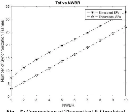
[image:6.595.50.269.250.441.2]Different initial probability of transmission was chosen to represent different types of network burst rates (NWBR). The NWBR value corresponds to the number of nodes that wake up and access the channel simultaneously. For instance, NWBR5 corresponds to a network load where 5 nodes wake up and try to access the channel simultaneously. Number of synchronization frames required to assign time period to individual motes is calculated and plotted in fig. 4.
Fig – 5: Comparison of Theoretical & Simulated Synchronization Frames
Fig. 6 shows the probability of successful transmission which indicate the performance of RA protocol and MAC protocol. Now it can be conclude that if prediction of cluster head which is considered 1/7 in this is write then probability of transmission is maximum and according to the graph it is around 40%.
Fig – 6: Probability of Successful Transmission
5. CONCLUSION
This research work concludes that the in case of double receiver model that is used for serving nodes having high priority to send data to cluster head consumes less energy as compared to basic single receiver model. Performance of optical D-MAC protocol is analysed in terms of energy consumption by sensor network, network burst rate, probability of successful transmission and window size. due to which network congestion shorted our shortly and different time slots are assigned to different nodes. Implementation of direction media access protocol is successful. A new concept of urgent node serves at duration of random access protocol assigning performed good and an improvement of 73% less power consumption is achieved. Basic model DMAC average energy consumption is 2.63uJ, while proposed model’s energy consumption is 0.879uJ.
REFERENCES
1. Dargie, W. and C. Poellabauer, Fundamentals of wireless sensor networks: theory and practice2010: John Wiley & Sons Inc.
2. Sohraby, K., D. Minoli, and T.F. Znati, Wireless sensor networks: technology, protocols, and applications2007: Wiley-Blackwell.
3. Short-range optical wireless communications. O'Brien, D.C., et al. 2005. Wireless World Research Forum.
4. Free space optical sensor network for fixed infrastructure sensing. Agrawal, N., Milner, S. D. and Davis, C. C. 2009. Proc. SPIE, Free-Space Laser Communications IX. Vol. 7464.
5. Gigabit class high-speed indoor optical wireless; system design, challenges and results. O'Brien, D. C., et al. 2010. Proc. SPIE, Free-Space Laser Communications X. Vol. 7814.
6. Wireless Optical Network for a Home Network. Bouchet, O., et al. 2010. Proc. SPIE, Free-Space Laser Communications X. Vol. 7814, pp. 781406:1-9.
7. High data-rate optical wireless communications in passenger aircraft: Measurements and simulations. O'Brien, D. C., et al. 2008. 6th Internation Symposium on Communication Systems, Networks and Digital Signal Processing, 2008. CNSDSP 2008. pp. 68-71.
8. Free space optical sensor networking for underwater sensing applications. Agrawal, N., Milner, S. D. and Davis, C. C. 2009. 2009 5th International Conference on Intelligent Sensors, Sensor Networks and Information Processing (ISSNIP). pp. 475-480.
[image:6.595.44.268.544.725.2]© 2018, IRJET | Impact Factor value: 7.211 | ISO 9001:2008 Certified Journal | Page 2848 10. J. Derenick. Multi-Robot Systems: From Swarms to
Intelligent Automata, Alan
C. Schultz and Lynne E. Parker (eds.), chapter Hybrid Free-space Optics/Radio Frequency (FSO/RF) Networks for Mobile Robot Teams. Springer, 2005.
11. Angle diversity for non directed wireless infrared communications. Carruthers, J. B. and Khan, J. M. 2000, IEEE Transactions on Communications, Vol. 48, pp. 960-069.
12. Free-space Optics based Sensor Network Design using Angle-diversity Photodiode Arrays. A. K. Ghosh, S. Kunta, P. Verma, R. C. Huck. 2010. Proc. SPIE, Free-Space Laser Communications X. Vol. 7814.
13. Analysis of compound parabolic concentrators and aperture averaging to mitigate fading on free space objects. Wasiczko, L. M., Smolyaninov, I. I. and Davis, C. C. 2004. Proc. SPIE, Free-Space Laser Communications and Active Laser Illimuniation III. Vol. 5160, pp. 133-142.
14. Welford, W. and Winston, R. High Collection Nonimaging Optics. New York : Academic Press, 1989.
15. J. Derenick. On the deployment of a hybrid fso/rf mobile ad-hoc network. In IEEE/RSJ International Conference on Intelligent Robots and Systems, 2005.
16. D. Wang and A. A. Abouzeid. Throughput capacity of hybrid radio-frequency and free-space-optical (rf/fso) multi-hop networks.
17. E. Bisaillon, D. F. Brosseau, T. Yamamoto, M. Mony, E. Bernier, D. Goodwill, D. V. Plant, and A. G. Kirk. Free-space optical link with spatial redundancy for misalignment tolerance. IEEE Photonics Technology Letters, 14:242– 244, February 2002.
18. G. E. F. Faulkner. A cellular optical wireless system demonstrator. In IEEE Colloquium on Optical Wireless Communications, pages 12/1–12/6, 1999.
19. G. C. Boisset. Design and construction of an active alignment demonstrator for a free-space optical interconnect. IEEE Photonics Technology Letters, 7:676– 678, June 1999.
20. C. Chuah. Capacity of multi-antenna array systems in indoor wireless environment. In Proc. of IEEE Global Commun. Conf., Sydney, Australia, nov 1998.
21. D. C. O’Brien, et al. High-speed integrated transceivers for optical wireless. IEEE Communications Magazine, 41:58–62, March 2003.
22. P. Djahani. Analysis of infrared wireless links employing multibeam transmitters and imaging diversity receivers. IEEE Transactions on Communications, 48:2077–2088, December 2000.