8
A Metadata-based Framework for Object-Oriented
Component Testing
M Nawaz Brohi
Fakhra Jabeen
Department of Information Technology Department of Information Technology Preston University, Ajman Preston University, Ajman
United Arab Emirates United Arab Emirates
ABSTRACT
Component-based systems are becoming prevalent at a rapid pace. With the growing demand for components, there arises a need for adequate component testing procedures. The component testing process at user end suffers with the unavailability of source code, which precludes extrapolating standard testing approaches. Effective Object Oriented (OO) component testing techniques require structural and behavioral information of component as a necessary test support element. We propose an OO component-testing framework that relies on utilization of metadata captured in discrete descriptors. A component developer generates a
Component-Descriptor (CD) concomitantly with the component that provides behavioral analyses. The user chooses a component by browsing CDs and preparing
Component Requirements Descriptor (CRD). Using analyses of component behavior in CD and of minimal requirements in CRD, third-party tester (TPT) conducts user directed component testing and reports bugs to the provider in the form of Component-Test-Specification-Descriptor (CTSD). The provider eliminates those bugs and returns the modified component and CD to TPT. This continues until TPT is satisfied with the reliability of component services. TPT then packages CTSD with the component for the user. The component provider, user, and TPT, each has the responsibility for descriptors unique to their perspective. The proposed framework attempts to eliminate the dilemma of unavailable information and supports objectivity in component testing process.
Keywords
Metadata, Component Testing, Descriptor, Software Testing, Software Components, Component metadata
1.INTRODUCTION
Software applications have become a necessary element of almost every aspect of business and industry. From laboratory tests through delicate neuro-surgical procedures, the processes are becoming increasingly software dependent. Software development processes must keep up with the increasingly sophisticated needs for dependable software production in a dynamic world. The production of software components is one of the advancements that respond to the demand of rapid software production. Components are envisioned as reusable building blocks allowing production of large software systems in much less time and reduced cost. Software component is a
unit of composition with contractually specified interfaces and explicit context dependencies only [1]. A software component can be deployed independently and is subject to composition by third parties. Object Oriented software components with special features (e.g., inheritance), which ease the software development process, also require novel approaches for testing to achieve a high degree of fault detection. The scope of OO software components may vary from a class to a cluster of classes. Typically a class can be treated as an independent component [2]. The benefits of using components in general and OO components in particular can only be practically affirmed if these are bug free and present reliable services in the system.
Software component lifecycle differs from conventional software presenting various challenges as Component Based Software Development (CBSD) is generally scattered over multiple organizations. This is primarily true for Commercial off the Shelf (COTS) components where component is developed once and can be used by multiple users. That is the software component is implementation transparent, the source code of component is transparent to the developer only and the user can access the component services without knowing the implementation details. It is a distinguishing characteristic of software component as it facilitates reuse, and the component developer also conceals the proprietary information. At the same time, implementation transparency affects the component user, due to the lack of information for performing component integration testing. IEEE defines integration testing as “testing in which software components are combined and tested to evaluate the interaction between them” [3]. Indeed, unit testing cannot confirm the reliable behavior of components in a new system; hence another testing campaign—by the component user—is essential to attain an acceptable reliability level. Council W.T termed testing by the component user during its implementation in the real environment as second party testing [4].
[15]. This generation of metadata still requires an extra code embedded to access component behavior. Extra code in component implementation aggravates component complexity. The existing mechanisms such as summary information, and metadata, as discussed, do not provide a generalized form of information representation with the component. Another approach addresses the need for additional information by attaching Unified Modeling Language (UML) Models with component [16]. The UML Models reflect component behavior and assist component user in the integration testing process. However, UML Models such as sequence diagrams and collaboration diagrams allow generation of source code thus affecting the implementation transparency of component [6]. In short, the main problems, which arise existing processes of adding information with software components are that these processes:
Lack formalism for information representation, Interpretation of information is not clear due to its
non-uniformity. Hence requires to understand the representation prior to interpreting the meaning, and Expose component implementation, allowing
reverse engineering.
On account of these issues, we propose a framework, which attempts to resolve these problems. These issues are not completely resolved, however it can be said that the proposed framework minimizes the effect of problems discussed above. Our proposed framework enhances component testability by defining a uniform information flow in component life cycle so that component can be reused effectively. This research can be considered as an extension of the Metadata proposal given by Orso [14]. Next section is the related work followed by a discussion of proposed framework.
2.RELATED WORK
Software components with the utilization of minimum resources allow rapid software development. The widespread use of component-based software has triggered research efforts for effective component integration testing. Harrold, M.J. defined two perspectives component user, and component developer [8]. These are significant while conducting testing of commercial off the shelf components. The commercial off the shelf component can be tested directly by the users or TPT can be requested to conduct component testing. Third party testing ensures objective testing process as reported by Ma, Y.S. [17], Councill W.T. [4] and Vaos, J.M. [18]. Ma, Y.S. proposed a framework for component third party testing [15]. A three-step process is defined using metadata. First, TPT provides guidelines and supporting tool to the producer. Second, producer generates test-package using these guidelines. Test-package consists of information to deploy and test the component and to audit the test suit of the component in the form of metadata. Third, TPT checks the conformance of test-package with guidelines provided to producer, executes the test package, and generates a test report. An evaluation of the framework demonstrates that TPT met some problems while executing the test-suite. It was mainly because the developers providing the test suite lacked testing skills. In general third party testing provides objectivity in component testing.
In 1999, Harrold, M.J. also initiated the idea of component metadata for software engineering tasks [8]. The issue of missing component information complicates analyses and testing activities. A test model defined for OO component testing [5]. The test model is based on the identification of test
elements for conducting component integration testing. Test elements require developers to attach additional information with the component that includes interface, event, context dependence and content dependence. Information added to the component to enhance analysis and testing of interfaces is generally termed “component metadata” [14]. The added information becomes a gauge for the component testability. Gao J defined testability metrics, which are also assessed from the metadata [19]. Several integration testing techniques existing in literature use some form of metadata in the testing process.
Bertolino and Polini proposed component deployment framework for component users [20]. The team used the basic classification of testing (i.e., unit, integration, and system testing), and termed the unit testing phases as component testing, integration-testing phase as deployment testing. In framework user performs an analysis of component requirements before actually deploying the component [8]. The user defines a virtual component through analysis, which partially simulates anticipated component requirements, however does not require complete component development. The deployment-testing framework allows the user to select a set of available software components, and to evaluate the functionality of each real component through testing in the system environment. It permits to test multiple available components, by matching the component behavior and outputs. However, it requires the component under test to have the runtime access mechanisms enabled by the component developer. Thus it limits the framework for testing only the components that have runtime access enabled.
Built In Testing (BIT) is another approach to increase component testability. BIT requires component developers to embed tests in software component implementation to support self-testing. Wang Y used BIT for constructing maintainable software [21]. The tests were developed in component source code as extra member functions; component in this approach operates in two modes, which include normal mode and maintenance mode. In normal mode component performs required functionality, and in maintenance mode the interfaces for built in tests can be activated as other component interfaces. Some of the techniques to add metadata with the software component for improving component testability also use BIT approach with slight variations. These include self-testable software component by Martins [22] and Self TEsting COTS (STECC) Strategy by Beydeda and Gruhn [23]. BIT approaches demand extra programming effort and increased complexity in the development of a component as tests are built in the component implementation. Only those aspects of component can be tested that are enabled by the component developer. In brief, BIT improves component testability, but it is limited to a fix level as defined by the developer.
10
3.
MOTIVATION
The momentum of proposed framework is to assist the reliable integration of software component. Our framework aims to enhance component testability by attaching some additional information with the component, and thus proposed framework makes following contributions to the OO component testing:
It provides mechanisms to schematically document essential OO component behavioral information in the form of three comprehensive descriptors. The information in these descriptors boosts up the test support capability of software component, and is structured in such a manner that specification and implementation are kept separate, and independent. The idea of adding descriptor is not new. It was adopted from the deployment descriptor used in distributed component, e.g., EJB component [24]. Since existing techniques that provide the specification with the component tend to embed the same into the very implementation of the component [25], which imposes the serious threats to the OO component testing. This allows the user to access only a specific set of information and also affects the component implementation transparency. The proposed framework defines descriptors, which contain structural and behavioral details of the component according to the requirements of each role in OO component testing framework.
The proposed framework incorporates TPT. The idea of TPT is already proposed and supported by Ma, Y.S. [17], and Councill W.T. [4] and Vaos, J.M. [18]. As the developer may not be a testing expert, and may have a bias in revealing bugs in the component. Our framework allows the TPT to treat a component as a black box for testing requirements defined by the user in a descriptor. The TPT also verifies component behavior provided with the component in another descriptor by the developer.
o This enables impartial component testing.
o Test results appended by TPT increase component user confidence in software component.
o Conducting component testing based on user requirements; TPT simulates virtual integration testing before real integration testing. Thus reducing the critical pitfalls at the component user end.
o In addition, TPT having knowledge and software testing skills enhances the component’s testing support capabilities. TPT further supplements each component with test
specifications including test oracles and test results in a schematic notation.
o The user can decide whether to use the component or to look for another solution based on the test results by TPT. This again reduces the integration cost and hazards for inappropriate component, which cannot be avoided in conventional practices.
o Test results also present important information for comprehensive integration testing by the user, and can additionally be used for test optimization at user end.
o The test specifications by the TPT provide a measure of the reliability of the component,
which can in turn influence its reusability. These specifications also add to the test history of software component and can be used to perform configuration management during maintenance phase of software component.
The proposed framework also fosters component reusability. Moreover, multiple users can access and analyze component functionality, and test components in a particular usage context, adding to component test history. This separates analysis and implementation of software component while defining an effective testing process for OO software components. Once tested by TPT, the test-specifications are kept with the component, so that if same component is again tested then existing test history of component can be reused. In this way, the addition of information with the component in our framework attempts to reduce the risk of failures in software systems.
4.METADATA BASED COMPONENT
TESTING
4.1.
The proposed frame work
The key players in proposed framework are component provider, user, and third party tester. The proposed framework attempts to resolve weaknesses in prevailing component integration testing process, by establishing a uniform information flow among key players. Component-provider (developer/assembler) usually refers to the single team that produces the component. Component user acquires the component to integrate in software system. TPT again may be a team or an organization that tests a component on behalf of the end user to ensure minimum operability for integration testing. Our approach mainly focuses on providing a communication mechanism between key players, and providing each with sufficient component test-specifications he/she requires for a successful component testing process.
The information flow is based on metadata contained in descriptors that is a practical application of metadata approach proposed by Orso [14]. The existing metadata based techniques for component testing, fail to provide the formal or standard means of information transfer between the concerned parties. In addition they are also unsuccessful in providing the complete and specialized testing information for integration testing. For these reasons, we propose descriptors in a standard format, whose contents are tailored to assist specific tasks in component integration testing. The representation of every descriptor is accomplished using standard notation for uniformity in information flow. Instead of defining a new proprietary standard for descriptors’ representation, we have chosen standard Extensible Markup Language (XML) notation [26].
4.1.1. Roles in the proposed framework
The proposed framework realizes the separation of concern principle by defining distinct set of responsibilities for each role. This separation of tasks allows executing the component test lifecycle activities separately by every role in an isolated domain. Moreover a formal means of communication is defined providing all roles the required set of information for conducting testing in the framework. Each of the roles has well-defined and specialized responsibility. This section presents the responsibilities of key roles in our framework, including provider, TPT and user (see Table 1). Component Provider: can be a developer or an assembler. The developer produces software components according to the market requirements that are generally used per se by the user or application developer. The assembler tests and assembles similar or linked classes into single component if required by the user. This assembly helps in simplifying integration testing of component, as the assembler tests integration of the constituents with full access to component source code. The component provider finally provides a formalized specification of the component, tuned to assist in testing, with the component, in the form of Component Descriptor, as in steps 1, 2, and 5 of Figure 1.
Component User: can browse through CD placed in public access directory (see step 3 in Figure 1). Typically users do not define the expected requirements of a component in any standard form/notation. Our framework allows the user to access component CD and to specify the anticipated requirements as metadata packaged in component CRD (see step 3, 6 in Figure 1). On choosing the component, the user avails the services of TPT to acquire confidence of component services. The user receives the component packaged with CTSD and CD. The test information in CTSD reduces the user effort, thus simplifying the integration testing (see step 11 in Figure 1).
Table 1. Roles and Responsibilities in OO Component Test Framework Component Provider Compone nt-User Third-Party Tester (TPT) Developer Assemble
r R e s p o n s ib il it ie s Develops component s, based on
market requiremen ts Assemble s related compone nts on demand Selects component by browsing through CD’s of available component s Tests component for component user using informatio n from the provider and the user Prepares Componen t Descriptor
(CD) of component Reduces integratio n testing pitfalls of related compone nt for the same user Prepares Componen t Requireme nt Descriptor
(CRD) of selected component Prepares Componen t Test Specificati on Descriptor (CTSD) of component under test
CD is packaged with each component going to the TPT by provider
CRD of component is supplied to TPT TPT tests component and sends failed test results to provider (in CTSD), after modificatio ns finally prepares CTSD going to the user with the CD and component D e sc r ip to r
s CD adds additional information with OO
component for analyzing component
behavior for testing
CRD encloses minimal, specific operational requireme nts for TPT CTSD holds test specificatio ns of the component
, to help the user either to select the component or look for another solution T e s ti n g L e v e ls Unit tests each componen t Integrates and tests assembled componen t Performs integration testing after accepting tested component
, CD and CTSD Impartially performs unit testing and virtual integration testing for the user
12
4.1.2. Information flow cycle in metadata based
component testing framework
Complete information flow among key players is presented using descriptors, which capture metadata in the component-test-framework. The information flow cycle is established by attaching specific descriptors with component by every role in the framework. Thus the sequence of these events/occurrences of adding the descriptors (see Figure 1) progresses in the following manner:
1. Component providers registered in the framework develop components according to the market requirements. A CD is generated and associated with each component by the developer.
2. Component provider makes CDs of developed components available in a public directory (this can be an online facility to provide public access) for all component users.
3. The component user browses through available CDs of components. The uniformity in CD format allows component user to select a software component according to the user requirements.
4. If a component user requires two or more components and the selected components are related, then component assembler integrates components to form a composite unit. The assembler is considered as part of component provider organization rather than a separate organization.
5. Selected component is sent to TPT with its CD for complete test execution.
6. Once a component is selected, the user prepares a CRD descriptor, for TPT, by browsing through CD of selected component. The user specifies in the CRD, the criticality of specific features of the component to be tested in the user environment.
7. TPT uses CD and CRD for testing component behavior in an impartial manner and virtually simulates the integration testing of software component.
8. The scenarios or conditions of failed tests are sent to provider in CTSD, for correction by developer as indicated by TPT.
9. The developer sends the modified component, and CD to the TPT for repeating test process. 10. The steps 8 and 9 continue to repeat in a cyclic
manner until TPT verifies component’s compliance with CRD and CD. It results in completion of comprehensive CTSD for each tested component.
11. The component is finally sent to the user packaged with CD and CTSD.
Software Component
CTSD
Software Component
CD
Software Component
CD CD CD CD CD
Repository of CDs in a public Directory
Browses Component User
CD
Third Party Tester Component
Provider
CTSD
CD
CRD
Software Component
CRD
CD
CD
Assembler Developer
3
6
11
8
2
1
4
9
5
Figure 1: Metadata Based Object Oriented Component Testing Framework
4.1.3
Descriptors in the proposed framework
The proposed framework attempts to resolve component-testing problems by imparting comprehensive descriptors among various roles in the component life cycle. A subset of fundamental engineering processes are simulated in component lifecycle, i.e., the developer provides components having a set of requirements, the user provides requirements, TPT attempts to verify that component does indeed meet the requirements (iterating with the developer if necessary). TPT conducts component testing with a perspective of user requirements. It is termed as virtual integration testing as the real user environment is not simulated by TPT rather only the specifications in CRD are tested by the TPT. For this we say that virtually integration testing is simulated at the TPT end. In the proposed framework, the augmentation of component test specification, results in enhanced component reuse. Mainly three descriptors (i.e., CD, CRD and CTSD) establish communication among key players. The CD, CRD, and CTSD follow a defined schema, and are under individual ownership by each of the key players who are responsible for supplying content for their descriptors that complies with schema requisites.This section provides an overview of structural elements contained in each descriptor. An example is also presented to explain how the TPT and the user can practically use the information kept in the framework descriptors while conducting component testing. The example is an Account class developed as a unit component using Java language, which contains the XML files of AccountCD, AccountCRD, and AccountCTSD.4.1.3.1 Component descriptor
CD reflects complete component structure and behavior with the goal to facilitate component testing process without source code. Developers can prepare CD by using component source code and design artifacts such as state diagram, as developers
typically have full access to all component artifacts. Using both design and implementation to prepare CD also helps to identify any discrepancy between the two. CD elaborates entire set of component services, thus assists the user in analyzing desired component functionality. In addition, it also increases component reusability.
CD Schema Structure
The CD is built to store constraints on data and behavior of each object in the component. The elements and sub-elements in CD are also fully elaborated with their tags in AccountC.D. Elements that form the CD structure include following:
Component Configuration: Component configuration holds the developer identification and date of creation etc., so that when TPT reports bugs, the developer who created the component can modify to remove the errors.
Non-Functional Specification: Non-functional specifications contain the descriptions of specific hardware and software requirements for correct execution of component. Component user while choosing component can also check, by browsing through CD, whether these specifications match component user’s environment.
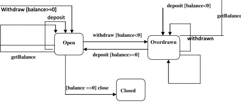
Component-structure (or functional specifications): The component structure element is of paramount importance in the CD, which contains a separate <class> tag for each class in the component. The extraction of the sub-elements of component structure from source code and state diagram is illustrated by an example of Account class. The elements of CD Schema are explained with an Account class developed in Java having simple functionality for brevity and understanding. Account class interface is shown as follows, and the state diagram of the Account class is given in Figure 2.
public class Account{ public Account(){
<method-body> }
public void withdraw(double amount){
<method-body> }
public void deposit (double amount){
<method-body> }
public double getBalance(){ <method-body> }
public void close(){ <method-body> }
private double balance; }
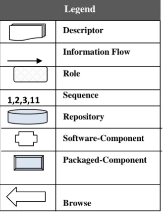
All method statements of Account are accessible only to component developer. The conditions on values of instance variables can be determined by analyzing method operations in code or state-diagram. From Account state Legend
Descriptor Information Flow Role
Sequence Repository
Software-Component Packaged-Component
Browse
14 diagram (Fig. 2) it can be observed that withdraw, deposit,
and getBalance methods are invoked only in Open and Overdrawn state. A close message cannot be triggered in over drawn state of object. This information is useful in determining the possible sequences of messages to be triggered for testing. Therefore, such information is kept in CD in component structure element for each class of component. CD elaborates behavior without exposing actual business logic. The sub-elements in component structure element of CD include following:
Inheritance hierarchy Attributes
Invariants {class invariant, state invariant} Methods.
The inheritance is a powerful feature of OO programs. For testing this feature, an inheritance hierarchy is kept in CD by providing the names of super class (es) of each class in CD. For example, consider a class C that inherits from B which itself inherits from A. The CD of class C must contain B and A as super-class names. Multiple inheritances generally introduce complexity in OO software thus it is not supported by the proposed framework. An object is represented by a set of attributes or instance variables. The state of an object is determined by values of its instance variables specified in the state. The balance attribute of Account class is provided in CD with a unique attributeID, name, data-type and an abstract specification of attribute by component provider. It is useful for TPT to access these values of attribute to test data type and possible range of the variable input values in the class or component.
[image:7.595.64.478.533.711.2]An invariant is a Boolean expression that specifies the required range of values or states of variables [27]. The developer determines class and state invariants. Tester uses invariant expressions at various points during testing to check correctness of component behavior. By using class and state invariant expressions, tester can produce test-data and test cases for each class.
Figure 2: Account Component State-Diagram
A class invariant specifies properties that must be true for object in any state of class [27]. It must be true after instantiation, upon entry and exit from every method, and just before destruction. An object may change states on method calls but all these states are a subset of class invariant. The developer attaches a class invariant expression in CD, i.e., derived by disjunction of instance variable states. For Account the state of object in class is defined by value of balance variable as shown in Figure 2. Thus the Account class invariant can be defined as: balance can have double value less than, greater than, or equal to zero. TPT can verify that any possible state of object during program execution cannot violate the class invariant expression. State Invariant expression is used for naming state and defining conditions on instance-variables for being in the particular state. Class modality is determined by the kind of constraints on message sequence or instance-variable value [27]. For a non-modal class the data boundaries for input and output need meticulous testing. Although a non-modal class does not impose constraints on sequence of messages accepted; however the messages are also tested for correct data modification and execution. As above-mentioned states in Account class are determined by value of balance variable, and the developer defines possible state invariants in AccountCD based on value of instance variable in the state-diagram (Figure 2).
Binder defines class behavior as an abstraction of the content of an object or the prior sequence of messages accepted, or both. The invariant expressions are defined in CD for testing valid sequence of messages. For every method in component, developer must specify following elements in CD by using both the design and the component source code:
Pre- and post-conditions
The type and valid range of method parameters and return values
A set of pre and post conditions is defined for each method in class by forming a Boolean expression comprising of state-invariants, and any other condition to be imposed on instance variables for method execution. For each method, the parameter values and return values are also specified with type and the valid or acceptable range of values for the method.
getBalance deposit [balance<0]
withdrawn
Overdrawn
Withdraw (balance>=0) deposit
getBalance
Withdraw [balance>=0]
withdraw [balance<0]
deposit [balance>=0]
[balance ==0] close Open
deposit Withdraw [balance>=0]
CD for component user
Component developer prepares CD for each developed component. The CD is placed in a public access directory so that various users can access and browse through the CDs of available components. The user can analyze component functionality via the brief descriptions attached with the component interfaces. If the user finds the component useful for the system, i.e., the component functionality is partially or fully equivalent to the user requirements then the user prepares a CRD using component CD. For TPT, user can prepare the CRD by browsing through the component CD, thus resulting in effective testing process by TPT. Consequently CD not only gives an overview of component functionality but also permits the user to specify the criticality of use or the usage level of required component interfaces.
CD for TPT
While preparing the CD, developer can append this information, which cannot allow the generation of same state diagram at the user end, rather the information in the state invariant can generate a super set of all possible state transitions. These state invariant expressions are utilized in defining the pre and post-conditions of each method in the descriptor. Instead of providing the conditions on variables in the method pre and post conditions the state-invariant expression name can be useful in building an understanding of the component behavior. State invariant expressions are thus used in the CD to facilitate TPT in component testing.
One method call in a class executes only if its preconditions are true and its execution is said to be complete if all post conditions are satisfied. In the proposed framework only the provider can access component source code. For this, developer must determine and define method specifications by analyzing component source code and state diagram (Figure 2) as mentioned earlier. Thus tester can easily derive the test oracles for testing correct sequence of messages by extracting the pre- and post- conditions for each method as provided in the CD. The correct message sequences assist in determining object behaviors especially when software components from different providers are integrated in the system.
4.1.3.2 Component requirement descriptor
The component user is allowed to provide specific requirements of the component services, in CRD, as expected by the user. The purpose of CRD is to allow the user to specify anticipated component requirements prior to the simulation of integration testing at the user end. These requirements are not comparable to particular software requirements specification. The user specifies the criticality of component services in the user environment. It mainly gives a general idea to the TPT about the component services required in particular by the user, while TPT conducts component testing. These requirements help TPT to simulate the virtual integration testing process by generating the test data according to the user requirements. Any inconsistency of requirement is communicated to user before actual deployment of component in the system.CRD schema structure
CRD schema structure is defined to accomplish the goal of providing TPT with the test specifications. For this reason in the proposed framework, user produces a CRD holding conditions on data values being manipulated and interface signatures that are of critical nature in the component user application. The Account component example is used for the explanation of CRD schema structure (AccountCRD), as mentioned earlier for CD elaboration (AccountCD). The component user makes use of selected component’s CD, to specify CRD schema elements according to user’s system requirements. The CRD schema structure mainly consists of following software component elements:
Non-functional specifications Interface specifications
The non-functional specifications by the user include system requirements such as operating system, memory, etc. Component user also supplies any assumptions pertaining to component execution environment. This element is incorporated in CRD for verifying component-conformity with particular user environment. The interface specifications in CRD are meant for providing information such as range and format checks on component data-values being manipulated, and conditions on component services being initiated in the system. It is the part of CRD used by TPT in validation of component functional requirements. In CRD interface-specification element further consists of sub-elements, which include:
Single tag for data members, and List of interface elements in the CRD. In data members tag user specifies type and range checks for each component data member for its integration test coverage in CRD. The user specifies a list of component interfaces, which are required by the user and are expected to be invoked in the user environment. These interface names acquired from CD, get higher priority during testing at TPT end. Component services or interface names are basically the public methods of the class or from the multiple classes in the component. With each name, i.e., interface name component user can also define conditions on each interface parameter and return as specifically required in the user’s system. In addition, user can specify the usage level of each interface. This level implies the testing level to be applied by the TPT, and ranges from 1 to 3, with 1 being the minimum usage level and 3 the maximum.
CRD for TPT
The objective of CRD is to collect essentially required testing specifications from component user in an understandable form. TPT can understand and then validate component functional specifications in CRD. TPT can also communicate with the developer for required modifications in component behavior.
16 CRD assists TPT in partially simulating the integration testing
and saving the additional testing effort.
TPT conducts component testing with a perspective of user requirements. It is termed as virtual integration testing as the real user environment is not simulated at TPT end rather only the specifications in CRD are tested by the TPT. Thus, virtually integration testing is simulated at the TPT end. Following arguments also support virtual integration testing by TPT:
TPT verifies requirements as mentioned in the CRD,
TPT generates input test data using domain analysis [27], a technique for test data generation to test classes. The input test data is generated based on the requirements stated by the user in CRD. It defines the boundary values for input data during domain analysis, and also manages for the volume testing of component by defining input data.
TPT tests the possible component configurations being specified by the user in the component CRD. It is essentially achieved by generating a sequence of interface calls as anticipated by the user. Component real environment can also be simulated at TPT end but it is not a requirement for our framework. TPT handles any mismatches with CRD or CD, and
component, and the inconsistencies or bugs in component can be communicated to the developer before actual deployment of the component in the system.
4.1.3.3 Component test specification descriptor
The CTSD provides a mechanism whereby the TPT can communicate understandable test oracles and results to the component user, and also to the provider. The TPT prepares CTSD using CRD, and CD. CTSD assists developer to remove bugs by sending a report of bugs detected by TPT in the component. CTSD provides an assessment of component services to the user and also assists in integration testing of component as it holds the test oracles and their results for each component.Test Data By Third Party Tester: The test data for executing component testing is generated based on the conditions imposed by the user in CRD. The simulation of virtual integration testing is achieved by generating the test data with conditions as imposed by the user. In this way the behavior of program is tested with the data values as expected in usage environment. Different techniques can be applied for test data generation, e.g., equivalence class and boundary value analysis [28].
For OO components, both primitive (e.g. integer, float etc) data types as well as the complex (objects) data types require test data generation. Hence, for the proposed framework, Domain Analysis defined by the Binder [27] is preferred for test data generation. In addition, Domain analysis also supports automation.
CTSD schema structure
CTSD schema structure at the basic level consists of a class tag in the component, and for each class TPT provides a tag <test-path> as an elemental tag in the CTSD, for every possible message sequence. TPT generates multiple test-paths for each class in the component. A test-path contains a message sequence, expected results after execution of message sequence, and total number of instantiations and the passed, failed, and inconclusive instantiations along with a description is given in CTSD.
The interfaces specified in CRD with high usage-level require elevated test coverage level. For each class in the component, the possible sequences of method invocations are generated and associated with a separate test-path in the CTSD. To achieve component user defined coverage, sequences of method invocations in the OO component are generated, by providing maximum coverage to those levels having high usage-level in the CRD. The generation of sequences is accomplished by browsing through the CD of software component, pre and post conditions of each method help to determine a super set of chain of sequences, which can get triggered from the component in an operational environment. The invariant expressions defined in the CD help the tester to determine the possible sequence of method invocations.
Test-oracles are the golden implementations or the correct expected outcomes of a test case for a test path [27]. The test cases are generated for testing the message sequences of class with the data generation mechanisms as defined earlier. This can simulate many instantiations of test data. The expected outcome of the test cases generated for the message sequence is derived or defined in terms of the oracle for each test-path of a class in the component. The test-oracle is derived in the form of an expression as shown in the AccountCTSD.
TPT verifies the actual test results obtained executing software component with the test-oracle to evaluate the test results against each instantiation as explained in next sub-section. TPT generates various instantiation of the test data, in order to test the sequences of method calls in a class with the data specified by the user in CRD. The oracle defined in the test-oracle is verified for each instantiation of data to check for pass/fail. Total number of instantiations, along with number of passed and number of failed are given in the instantiation tag of test path, so that an evaluation or test result can be established for each test-path.
CTSD for component provider
The first objective of CTSD is to notify the developer about the reported bugs in component. The CTSD assists the developer to remove the bugs in the component by sending a report of the bugs detected by the TPT, which contains a total number of bugs detected with the test oracles.
component configuration or a new component configuration has to be defined for the required change.
In the proposed framework, the augmentation of component test specification, results in enhanced component reuse. Once a component is developed, and tested to achieve a certain level of reliability before delivering to the user. Another user may again request the same component resulting in the reuse of component’s existing test-history. TPT reviews the test history and the specifications in CRD prior to conducting component testing according to CRD. A situation may occur that the elements of component specified in CRD are already tested with their results stored in component test history. In this way, the test history of component can also be reused, saving the testing effort. For modified components the test-history also needs to be modified, so that regression testing of component can be conducted to reveal errors.
CTSD for component user
TPT then prepares a CTSD packaged with component to the component user. The CTSD descriptor assists component user in integration testing of software component by providing test oracles and their results. CTSD also provides an assessment of component to the user prior to its incorporation in the system. It also assist the user in performing integration testing as the user mentions the usage level of each interface in the CRD, hence testing is conducted according to the requirements resulting in a simulation of virtual integration testing.
The metadata-based framework in this way utilizes three descriptors attached by each key player to facilitate the component testing. Allowing the TPT to generate test specifications with a consideration of component user requirements simulates the partial integration test. The component user finally receives the software component with the added descriptors thus reducing the hazards in integration testing process at the user end.
5.CONCLUSION AND FUTURE WORK
The primary motivations of the proposed framework are to minimize the affect of lack of information with the component and to define impartial component testing process. It is intended to be generally applicable in all OO software environments. By facilitating the TPT to understand object oriented component requirements, and its integrations; the idea of user-directed testing is incorporated. Three discrete descriptors prepared by the component provider (developer/assembler), user, and TPT are used in the proposed framework, to provide an effective mechanism for communicating test information to component user and TPT. The CD, CRD, and CTSD follow a defined schema, and are under individual ownership by each of the key players who are responsible for supplying content for their descriptors that complies with schema requisites. A formal notation for added information can enable unambiguous communication of component behavior to multiple users. Accordingly, a uniform schema is defined for component descriptors, in a form that is understandable by all concerned parties. Component provider and user supply the CD and CRD, respectively, to the tester, and in this way assist automated, and objective testing process. The TPT generates test oracle, test data and test cases to execute component testing, and stores test specifications in the CTSD. This framework in its current form supports automation due to the hierarchical structure of XML, and provides component unit testing as well as virtual integration testing. The proposed framework can also be extended tosupport maintenance tasks in component testing lifecycle. Complete automation of this framework can be presented in the future works. This automation will help in performing an evaluation of the proposed framework so that a proof of concept can be established.
REFERENCES
[1] Szyperski, C., 1998. Component Software—Beyond Object Oriented Programming, The Component Software Series. Addison-Wesley.
[2] McGregor, J.D., Sykes, D.A., 2001. A Practical Guide to Testing Object Oriented Software, Addison-Wesley, 1st
edition, Series Editors.
[3] “IEEE Standard Glossary of Software Engineering Terminology,” ANSI/IEEE Standard 610-12-1990, IEEE Press, New York, 1990.
[4] Councill W.T. 1999. Third-party Testing and the Quality of Software Components, IEEE Computer, 55-57.
[5] Bhor A. 2001. Software Component Testing Strategies, Technical Report UCI-ICS-02-06, Department of Information and Computer Science, University of California. Irvine United States.
[6] Wu, Y., Pan, D., Chen, M. 2001. Techniques for Testing Component-based Software, In 7th IEEE International Conference on Engineering of Complex Computer Systems (ICECCS) Sweden, 2001, pp. 222-232.
[7] Rosenblum, D.S. 1997. Adequate Testing of Component Based Software, Technical Report TR97-34. University of California at Irvine.
[8] Harrold, M.J., Liang, D., Sinha, S. 1999. An Approach to Analyzing and Testing Component-Based Software, In First International ICSE Workshop on Testing Distributed Component-Based Systems, Los Angeles.
[9] Harrold, M.J. 2000. Testing: A Roadmap, 22nd International Conference on Software Engineering ACM Press.63-72.
[10] Dogru, A.H., Tanik, M.M. 2003. A Process Model for Component-Oriented Software Engineering, IEEE Software, 34-40.
[11] Gao, J.Z, Tsao, H.-S.J. and Wu. Y.2003. Testing and Quality Assurance for Component Based Software, Artech House, Computing Library.
[12] Weyuker, E.J. 1998. Testing Component-Based Software: A Cautionary Tale, presented at IEEE Software, 54-59.
[13] Gao.J., Lan.Y and Jin. M. 2008. A Model of Third-Party Integration Testing Process for Foundation Software Platform, Young Computer Scientists 2008 ICYCS 2008 The 9th International Conference for (2008), 1199-1204. [14] Orso, A., Harrold, M. J., and Rosenblum, D. S. 2000.
Component metadata for software engineering tasks, In Proceedings of the 2nd International Workshop on Engineering Distributed Objects (EDO 2000), 126-140.
18 [16] Wu, Y., Chen, M. and Offutt, J. 2003. UML-based
Integration Testing for Component-based Software, Proc. Of International Conference on COTS-Based Software Systems (ICCBSS), Ottawa. Canada, 251-260.
[17] Ma, Y.S., Oh, S.U., Bae, D.H., and Kwon, Y.R.2001. Framework for Third Party Testing of Component Software, Proceedings of the Eighth AsiaPacific on Software Engineering Conference (8th APSEC). [18] Vaos, J.M. 1998. Certifying Off-the Shelf-Components,
IEEE Computer, Los Alamitos, CA, United States, 53-59.
[19] Gao. J. 2000. Challenges and Problems in Testing Software Components, In Proceedings of ICSE 2000's 3rd International Workshop on Component-based Software Engineering: Reflects and Practice, Limerick, Ireland.
[20] Bertolino, A., Polini, A. 2003. A Framework for Component Deployment Testing, 25th International Conference on Software Engineering, Portland, Oregon, 221-231.
[21] Wang Y., King G., Wckburg H. 1999. A Method for Built-in Tests in component-based Software Maintenance, IEEE International Conference on Software Maintenance and Reengineering, 186-189.
[22] Martins, E., Toyota, C.M., Yanagawa, R.L. 2001. Constructing Self-Testable Software Components, In
Proceedings of the International Conference on Dependable Systems and Networks, 151-160.
[23] Beydeda S., and Bruhn, V.2003. Merging components and testing tools: The Self-Testing COTS Components (STECC) Strategy, In Proceedings of the 29th EUROMICRO Conference “New Waves in System Architecture”, Germany, IEEE, 107-114.
[24] DeMichiel, L. G. 2003. Enterprise Java Beans TM Specification, version 2.1, Technical report, Sun Microsystems.
[25] Morris, J., Lee, G., Parker, K., Bundell, G.A., and Lam, C.E.2001. Software Component Certification, IEEE Computer, 30-36.
[26] “World Wide Web Consortium:
XML,”http://www.w3.org/TR/2000/RECxml-20001006. Centre for Intelligent Information Processing Systems. 2001.
[27] Binder, R.V. 1999. Testing Object-Oriented Systems Models, Patterns, and Tools, Object Technology Series, Addison Wesley, and 1st Edition.