Design of a Fast and Autonomous Complex Line Tracker
and Fully Controlled Robot by Limit Switches
Amevi Acakpovi
Accra Polytechnic (Ghana) P.o Box: GP561
Salifu Osman
Accra Polytechnic (Ghana) P.o Box: GP561
Olufemi O.Fatonade
Accra Polytechnic (Ghana) P.o Box: GP561
ABSTRACT
The explosion of microcontrollers and microprocessor applications has led to a rapid growth in the area of robotics especially line follower robots. Controlling line follower robots to travel over a complex race course pose some instability and speed problems. This article mainly deals with the design of an electronic three wheeled-robot capable of tracking a black line by means of infrared sensors and also capable of moving through a given trajectory by control of limit switches at a relatively high speed. The method consists first in developing a program written in Basic language under Microcode plus environment and loading it into the microcontroller to control the robot. Various PWM techniques were adopted in the programming to handle the turning left, right, the moving forward and backward. In addition, necessary hardware involving 6V DC motor, limit switches, infrared sensors, 6V battery and others have been assembled on a PIC16F877 microprocessor board and put in a case, shaped as a vehicle. H bridge motor control and PWM were used to control the DC motors. The implementation is finally successful. The robot can move autonomously across a black line and also pass through a complex race in absence of black line by means of limit switches. The motor can complete a race of 2m in 10s and turn at angles less than 30 degree while remaining stable.
General Terms
Automation, Microprocessor/Microcontroller programming, Intelligent wireless sensor programming.
Keywords
Basic language Programming, Microprocessor, DC motor control, infrared sensors, PWM, H-bridge.
1.
INTRODUCTION
Line follower robots have played a significant role in industries growth. Initially, used for the purpose of delivering mails within an office building, they are now serving to deliver medication in a hospital. With more accuracy in the design, the technology could even be suggested for running buses and other mass transit systems, and may end up as part of autonomous cars navigating the freeway. Many automation techniques help to design such robots. In the scope of our design the work will be focused on the use of PIC microcontrollers with programming of PWM for the control of the DC motors.
2.
PROBLEM STATEMENT
Line follower robots are popular in robotics industry. The ultimate reason to design a new robot is to have it computing with others in terms of speed and stability to travel over a complex race course. These factors lead to the following questions: What type of mechanical design can provide both speed and stability? What type of control could be applied on the motors to achieve a higher speed? How will the sensing of black line be done?
3.
OBJECTIVES
The main objective of this work is to design and implement a fast and autonomous robot that will follow a black line on a white board and also follow a given trajectory by using limit switches in absence of black line.
The following specific objectives will help achieving the main purpose:
- Design of a three wheels mechanically balanced robot
- Design of various PWM applicable for the DC motors using Basic language, in order to achieve turning right, turning left, moving forward or moving backward of the motor.
- Testing of the motor over a complex course race and adjusting the PWM to achieve the fastest speed
4.
REVIEW OF LITERATURE
Once again, the four-wheel model is not initially based on the speed aspect but rather on the stability and mobility. However additional works done respectively by Pedro F. Santana et al [3], Dmitry U. Panfilov et al [4], Thomas Bak et al [5] and Christophe Cariou et al [6] try to improve upon the speed of wheeled motors. Furthermore, several other types of control apply to wheeled robot: Gyula Mester [7] uses kinematic controls on a two wheeled robot with control strategies using a feed-forward compensator. Other motion controls by Thomas Bak et al [5] and Sonal Kalra et al [8] were totally hybrid type. They mainly use a non-holonomic dynamic system to model the robot. Finally Rick Bickle [9] and Electronics Design Laboratory [10] designed two fundamental control methods to apply to the DC motors to achieve high speed: H bridge method and PWM. The H-bridge enables the voltage to be applied in both directions allowing both forward and backward movement. The PWM has direct effect on the speed.
5.
METHODOLOGY
This project involves both hardware and software aspects. The design description will first start with the hardware aspect and explain their configuration after which will follow the software description.
5.1
Hardware Design
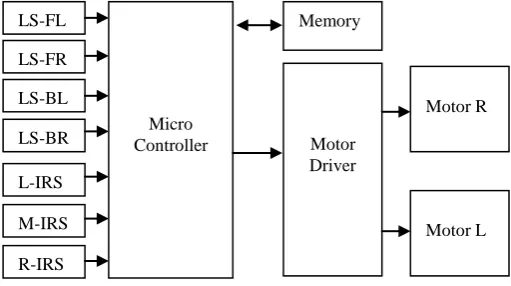
[image:2.595.51.307.494.637.2]The hardware deals with the mechanical design of the robot. The robot is made of four fundamental parts: Four limit switches coupled with bumpers, three infrared sensors used to track black line, the main microprocessor PIC16F877 board with LCD screen, the two DC-motor, their driving circuit and a 6V battery with charger. Two tyres are positioned at each sides at the back and the third on is in front. The front tyre is not coupled with any motor but can rotate in any direction. Figure 1 shows the bloc diagram of the robot controller. The shape of the robot is illustrated by Figure 2.
Legend:
LS-FL: Limit switch front left LS-FR: Limit switch front right LS-BL: Limit switch back left LS-BR: Limit switch back right Motor R: DC Motor right side Motor L: DC Motor left side
- Limit switches
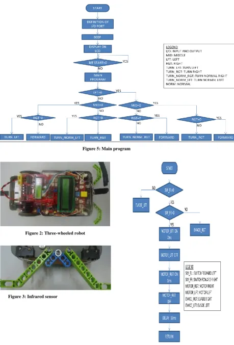
The limit switches are put in line under the car, two at the front and two at the back of the robot. In between the switches in front are two bumpers to enable the car detect obstacles. Figure 3 shows a picture of the configuration of the limit switches. When the bumper hit an obstacle, it closes the corresponding switch which sends a signal to the microprocessor. The signal is interpreted to take decision base on the program that is further explained.
- Infrared sensors
They consist of a set of three infrared sensors put together on the same printed circuit board and centered under the base board of the robot. The spacing between two consecutive sensors is about 1cm. Each sensor comprises both an infrared transmitter and receiver. The transmitter emits an invisible radiation which is sensed back by the receiver in case it falls on any object having black color. A solution-tape of 2cm width is set on a white board and the sensors are supposed to sense them and make the car follow the black line.
- Main microprocessor board
The main board is made of the PIC16F877 microprocessor with adequate extension to the various input and output ports and also an LCD screen.
- LCD Screen
The LCD (liquid crystal display) screen is a digital screen capable of printing 20 digits, including alphanumerical characters. It is used in this project to display information on the identity of the car. For instance the text displayed on the LCD screen is: “Robot PIC16F877.
- DC motors
Two 6V DC motor were used to control the two tyres at the back independently. The motors can be controlled to move in both directions using a drive circuit that will be further explained.
- Battery pack
The whole design is powered with a 6V rechargeable battery. The battery capacity of 12 Ah allow the robot to move continuously for 2 hours.
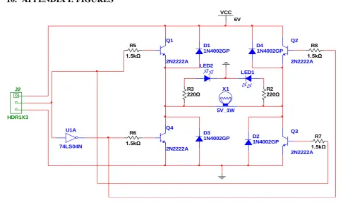
- Motor driving circuit
An H bridge DC motor direction control has been used with complemented inputs as shown by the Figure 4. The driver circuit is built for each of the DC motor. The three pins of connector J2 are made available for connection to the microprocessor board. The three pins on connector J2 are VCC, Control and GND. When the control signal sent from the microcontroller is digital 1, Q2 and Q4 are forward biased and then run the motor in Forward Direction. Conversely, when the control voltage comes to a 0 logic, Q1 and Q3 become forward biased and run the motor in reverse direction.
5.2
Software Description
The software description involves the use of artificial intelligence to execute the movement of the car. This is based on a specific program written in basic language and explained by the flowchart in Figure 5. The three infrared sensors are considered digital inputs. The 0 level means the sensor has detected a black line. All the decision boxes in the flowcharts are checking if the sensors have detected the black line or not.
Figure 1: Block diagram of the robot controller
LS-FL
LS-FR
LS-BL
LS-BR
L-IRS
M-IRS
R-IRS
Micro Controller
Memory
Motor Driver
Motor R
At start, the robot goes through an initialization process which involves the definition of input and output ports after which it beeps for 2 seconds and display a message on the LCD screen. The program continues by checking the state of “BITSART” which is a push button that the user must press to run the program. At the execution of the main program, the robot move in one of the following direction according to the state of black line sensed by the three infrared sensors: forward, backward, left, right, normal left or normal right.
- Forward
The forward procedure is explained by the flowchart in Figure 6. First the program checks if the back left or right switches are hitting an obstacle in which case it execute different procedures called “EVADE_LEFT” and “EVADE_RIGHT respectively. If there is no obstacle detected, the program runs the left and the right motors for 2ms and 1ms respectively, insert a delay of 18 ms and return back to the main program to check if the state of the infrared sensors continues to allow the robot to move forward.
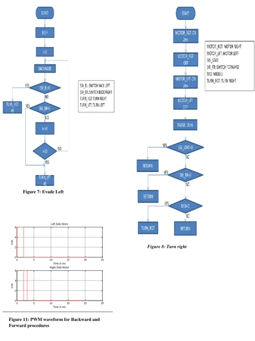
- Evade Left
This procedure allows the robot to evade left, which is explained in Figure 7. It is executed when the front left switch hit an obstacle. It is assumed to help the robot to change direction and avoid the obstacle. It consists of moving the robot backward for a certain distance and turns it right for 45o.
Otherwise, while moving backwards if the left or right back switches detect obstacles the robot turn right or left respectively at an angle of 45º.
- Evade Right
The procedure “EVADE_RIGHT” does the same thing as the “EVADE_LEFT” just that the process starts based on the detection of the front right switch. In this case the robot moves backward and turn left.
- Turn Right
As shown by the Figure 8, the robot turns right when there is no detection of black line. It turns right continuously, resulting into rotation until the sensors meet a black line. The procedure consists of turning on and off consecutively the right side motor and the left side motor for 2ms each and inserting a delay of 18ms. A click on the push button start can stop this procedure and go back to the main program. This is to allow the user to relocate the robot in order to detect a black race course instead of turning right continuously.
- Turn Left
This procedure is similar to the previous one but the whole system turns left.
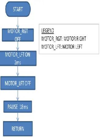
- Turn Normal Right
It is a slow turning into the right direction which is often called several times to allow the motor to turn at a desired angle. The procedure consists of turning the left motor for 2ms while keeping the right one off and then inserting 18ms delay. Figure
9 shows the flowchart. - Turn Normal Left
This procedure does the same thing as the “TURN NORMAL RIGHT” just that the turning direction is left.
- Backwards
Backward is achieved by turning on sequentially, the left motor for 1ms, the right one for 2ms and inserting a pause of 18ms. Figure 10 illustrate it.
6.
DISCUSSION OF FINDINGS
The completed robot is very stable owing to the mechanical aspect of the design. The robot was tested several times over a complex course race. It can travel over a straight line of 2 meters within 10s. The robot can also turn left or right at angles less than 30 degree without turning over, showing a considerable stability. In absence of black line the robot movement is controlled by the limit switches. For instance, if any of the front switches hit an obstacle, the robot move backward and turn slightly in the opposite direction before moving forward. This helps the robot to overpass an obstacle after hitting it for a certain limited number of times. This number is not fixe but depends upon the angle at which the robot hit the obstacle for the first time.
Furthermore, the timing diagram of Figure 11 explains the PWM applied for the forward and backward procedures. This diagram is derived from the flowcharts explained above. The average voltage level for both motors is given by:
After applying the formula, the voltage levels are respectively, 57% and 29% for the Left and Right motors.
7.
CONCLUSION
This article presents the design of a robot capable of following a black line and also capable to move in absence of black line with the control of four limit switches. The robot is successfully designed and capable of passing through medium to complex races at a relatively high speed. The robot is controlled by a program written in Basic language and loaded on a PIC16F877 controller which involves different PWM to control the various movements (turning left, turning right, moving forward or backward…). The design is an applied engineering example of using microprocessor/microcontroller in Electricity, Electronics and Computer technology.
Further works could improve the robot design by considering a more advanced mechanical shape (4 wheels) and also by using a speed drive for the DC motors in order to increase their speed.
8.
ACKNOWLEDGMENTS
Our thanks go to the experts who have contributed to the development of this line tracker robot, especially: Nicholas Ankrah and Samuel Inkumsa.
9.
REFERENCES
[1] Boe-Bot 2011. Boe-Bot Tank Treads. www.parallax.com.
[2] Huang,L., Lim, Y.S., David Li and Christopher, E.L. 2004. Design and Analysis of a Four-wheel Omnidirectional Mobile Robot. 2nd International Conference on Autonomous Robot and Agents, Decenber 13-15 2004, Palmerstorn North, New Zeland.
[4] Dmitry U. P. and Sergey B. T. 2007. Tracking of reference trajectory for wheeled mobile robot. Bauman Moscow State Technical University, ul. 2-aja Baumanskaja, 5, 107005, Russia., Moscow.
[5] Thomas B., Jan B. and Anders P. R. 2011. Hybrid Control Design for a Wheeled Mobile Robot. Department of Control Engineering, Aalborg University, Fredrik Bajers Vej 7C, DK-9220, Aalborg, Denmark.
[6] Christophe C., Roland L., Benoit T. and Michel B. 2009. Automatic Guidance of a Four-Wheel-Steering Mobile Robot for Accurate Field Operations. Journal of Field Robotics 26(6–7), 504–518 (2009), Wiley InterScience.
[7] Gyula M. 2006. Motion Control of Wheeled Mobile Robots. SISY. 4th Serbian-Hungarian Joint Symposium
on Intelligent System.
[8] Sonal K., Dipesh P. and Karl S. 2007. Design and Hybrid Control of a Two Wheeled Robotic Platform. Dept. of Mechanical Engineering, University of Auckland, New Zealand
[9] Rick.B. 2003. DC Motor Control Systems For Robot Applications.
[10] Electronics Design Laboratory. 2003. Robot DC Motor Driver and Speed Control. ECEN 2830.
10.
APPENDIX I: FIGURES
D1 1N4002GP
D2 1N4002GP D3
1N4002GP
D4 1N4002GP Q1
2N2222A
Q2
2N2222A
Q3
2N2222A Q4
2N2222A
R5
1.5kΩ
R6
1.5kΩ
R7
1.5kΩ R8
1.5kΩ
X1
5V_1W
VCC 6V
U1A
74LS04N
LED1 LED2
R2 220Ω R3
220Ω
J2
[image:4.595.45.532.220.517.2]HDR1X3
Figure 6: Forward Figure 3: Infrared sensor
Figure 5: Main program
0 5 10 15 20 25 0
2 4 6
Time in ms
V
o
lt
Left Side Motor
0 5 10 15 20 25
0 2 4 6
Time in ms
V
o
lt
Right Side Motor
[image:6.595.49.547.59.726.2]Figure 8: Turn right Figure 7: Evade Left
11.
APPENDIX 2: Program loaded in the Microprocessor in Basic Language
'*********************************************** '* Name :COMPLETE ROBOT.bas '* Hard ware :ET_ROBOR-877 '* CPU :PIC 16F877-20P '* HARD WARE SETUP: '* Servo-L <-- RC2 '* Servo-R <-- RC1 '* SW bumper left front <-- RA4 '* SW bumper right front <-- RE0 '* SW bumper left back <-- RE1 '* SW bumper right back <-- RA5
'* R-Light sensor <-- RA1 (AN1) '* l-Light sensor <-- RA0 (AN0) '* Notice : This program controls a robot car by using tracker sensors
'* switch bumper sensor and display message to LCD '*********************************************** INCLUDE "modedefs.bas"
DEFINE OSC 10 pulse_1ms CON 250 pulse_2ms CON 500 Motor_L VAR PORTC.2 Motor_R var PORTC.1 SW_START VAR PORTA.2 SPK VAR PORTD.1 RUN_LED VAR PORTD.0
SW_FL VAR PORTA.4 SW_FR VAR PORTE.0 SW_BL VAR PORTE.1 SW_BR VAR PORTA.5
LFT VAR PORTB.0
MID VAR PORTB.1 RGT VAR PORTB.2 i var byte
'****** DEFINE CONFIGURATION FOR LED ** Define LCD_DREG PORTD ' Define LCD_DBIT 4'PORTD [7:4] is LCD data pin
Define LCD_RSREG PORTD ' Define LCD_RSBIT 3 'RD3 is RS pîn Define LCD_EREG PORTD Define LCD_EBIT 2 'RD2 is E pin Define LCD_BITS 4 'LCD 4 bit mode
'****************** DEFINE INPUT AND OUTPUT ***************************
OUTPUT MOTOR_R OUTPUT MOTOR_L LOW MOTOR_r LOW MOTOR_L INPUT SW_START INPUT SW_FL INPUT SW_FR INPUT SW_BL INPUT SW_BR TRISB = $FF TRISD = 0 ADCON1 = 7
GOSUB BEEP2
LCDOUT $FE,1, " APOLY ROBOT ",$FE,$C0, "ITS ET-ROBOT 877"
GOTO WAIT_ST
[image:7.595.54.504.69.392.2]STOP_PRESS: PAUSE 50
[image:7.595.318.482.96.320.2]Figure 9: Turn normal right
IF SW_START = 0 THEN STOP_PRESS GOSUB BEEP2
WAIT_ST: HIGH RUN_LED
IF SW_START = 1 THEN WAIT_ST wait_1: PAUSE 50
IF SW_START = 0 THEN WAIT_1 low RUN_LED
'************************************************* ******************
' MAIN PROGRAM
'************************************************* ******************
MAIN: if (lft = 0) AND (mid = 0) AND (rgt = 0) THEN gosub FORWARD
IF SW_sTART = 0 THEN STOP_PRESS if (lft = 0) AND (mid = 0) AND (rgt = 1) THEN gosub TURN_RIGHT
IF SW_sTART = 0 THEN STOP_PRESS if (lft = 0) AND (mid = 1) AND (rgt = 0) THEN gosub FORWARD
IF SW_sTART = 0 THEN STOP_PRESS if (lft = 0) AND (mid = 1) AND (rgt = 1) THEN gosub TURN_NORM_R
IF SW_sTART = 0 THEN STOP_PRESS if (lft = 1) AND (mid = 0) AND (rgt = 0) THEN gosub TURN_LEFT
IF SW_sTART = 0 THEN STOP_PRESS if (lft = 1) AND (mid = 0) AND (rgt = 1) THEN gosub FORWARD
IF SW_sTART = 0 THEN STOP_PRESS if (lft = 1) AND (mid = 1) AND (rgt = 0) THEN gosub TURN_NORM_L
IF SW_sTART = 0 THEN STOP_PRESS if (lft = 1) AND (mid = 1) AND (rgt = 1) THEN gosub TURN_RIGHT
IF SW_sTART = 0 THEN STOP_PRESS GOTO MAIN
'************************************************* *************************
' WALKING FORMAT CONTROL
'************************************************* *************************
FORWARD: IF SW_FL = 0 THEN GOSUB EVADE_LEFT
IF SW_FR = 0 THEN GOSUB EVADE_RIGHT PULSOUT MOTOR_L, PULSE_2MS low MOTOR_L
PULSOUT MOTOR_R, PULSE_1MS low MOTOR_R
PAUSE 18 RETURN
EVADE_LEFT: GOSUB BEEP1 FOR I = 0 TO 30 GOSUB BACKWARD
IF SW_BL = 0 THEN TURN_R45 IF SW_BR = 0 THEN TURN_L45 NEXT I
TURN_R45:
FOR I = 0 TO 30
GOSUB TURN_NORM_R
NEXT I RETURN
EVADE_RIGHT: GOSUB BEEP1 FOR I = 0 TO 30 GOSUB BACKWARD
IF SW_BL = 0 THEN TURN_R45 IF SW_BR = 0 THEN TURN_L45 NEXT I
TURN_L45:
FOR I = 0 TO 30
GOSUB TURN_NORM_L NEXT I
RETURN
BACKWARD:
PULSOUT MOTOR_L, PULSE_1MS LOW MOTOR_L
PULSOUT MOTOR_R, PULSE_2MS LOW MOTOR_R
PAUSE 18 RETURN
TURN_RIGHT:
PULSOUT MOTOR_R, PULSE_2MS LOW MOTOR_R
PULSOUT MOTOR_L, PULSE_2MS LOW MOTOR_L
PAUSE 18
IF SW_START = 0 THEN RETURN IF SW_FR = 0 THEN RETURN IF MID = 0 THEN TURN_RIGHT RETURN
TURN_LEFT :
PULSOUT MOTOR_R, PULSE_1MS LOW MOTOR_R
PULSOUT MOTOR_L, PULSE_1MS LOW MOTOR_L
PAUSE 18
IF SW_START = 0 THEN RETURN IF SW_FL = 0 THEN RETURN IF MID = 0 THEN TURN_LEFT RETURN
TURN_NORM_R: LOW MOTOR_R
PULSOUT MOTOR_L, PULSE_2MS LOW MOTOR_L
PAUSE 18 RETURN TURN_NORM_L: LOW MOTOR_L
PULSOUT MOTOR_R, PULSE_1MS LOW MOTOR_R
PAUSE 18 RETURN
BEEP1: FREQOUT SPK, 100, 2000 RETURN
BEEP2: FREQOUT SPK, 100, 2000 PAUSE 100