Technology (IJRASET)
Analysis of Reversible Data Hiding Efficiency of
Images in Image Processing
Raj Kamal Chandrakar1, Mr. Neelabh Sao2
1
Student of Computer Science and Engineering, M.Tech Scholar, 2Assistant Professor Rungta College of Engineering and Technology, Bhilai (c.g.)
Abstract: Now a day data hiding has more attention in image processing field. Reversible data hiding has considerably new approach in image processing. Which allow original image to be completely recovered from marked image efficiently without any loss of data after extracted embedded message? The message included in image to use some pixels of image is called embedded data or massage. In this paper we proposed the Analysis of Reversible Data Hiding Efficiency of Images in Image Processing based on the different image histogram modification that uses pick point to hide message. This is an analysis of reversible data hiding using some bit position of image which is used to hide message. We analyse that in our proposed scheme use data hiding strategy to achieve large and efficient hiding capacity effectively and the data corruption or data distortion level of image data is low that means distortion of image data is minimized. Comparison of the performance of these scheme with the other existing reversible data hiding or multilevel data hiding schemes are provided to demonstrate the validity of our proposed scheme. It also can be apply in gray scale images and digital image or colour image. Histogram of image is designed to show graphically. This improves the data hiding efficiency. It is based on histogram modification methodology. In our proposed method draws graph between PSNR (peak signal to noise ration) and bpp to evaluate the data hiding capacity of an image and also we calculate the overall PSNR % loss and %distortion in an image after hiding a range of data. Data hiding is done in random manner that means random integer is generate and used to hiding on image this is done in layer by layer of image and also hiding time evaluated.
Keywords: Reversible data hiding, Histogram, Embedded message, host image, original image, Peak Signal to Noise Ratio (PSNR), bits per pixel (bpp).
I.INTRODUCTION
A. Image Processing
In image science image processing is processing of images using mathematical operation by using any form of single processing for which the input is an image, such as a photograph or video frame, the output of image processing may be either an image or a set of characteristic or parameter related to image.
B. Data hiding
Data hiding in image is the process of hiding included message or data in image like any code or signature etc. Data hiding refers embedding information into a cover object [1][2][3][4]. In data hiding text messages or codes like signature or numbers included in image using some pixels of image. Here the message or data is called embedded message or embedded data and this process is called data hiding. Here some bit pixels are used for hiding embedded message in image so some distortion may appear but it cannot seen (viewed) perfectly by human eye.
C. Reversible data hiding
Reversible data hiding is a type of data hiding where original image which is used in data hiding process is recovered by receiver side. That means the receiver finds the embedded data and also recovers the original image.
D. Data hiding process
Technology (IJRASET)
that means used in encryption for message in sender side and decryption for message in receiver side to safe the message from intruder access.
E. Data hiding applications
Data hiding applications can be classified into two categories according to the relationship between the cover image and the embedded message .
There is two type of application in data hiding Stenography and Digital Watermarking
Stenography is the first application in which the message in image is not related to the original image or covered image. The cover image has no value for the recipient, and receiver is not interested in the original cover image. The receiver only interested in data which is hiding in image. The purpose of data hiding is the data or massage keep secrete. This data in image is just like any secrete message, code or signature which is hidden. This results that the original cover image is not restored after embedded data or any message extracted.
Digital watermarking is the second application in which the included message is closely related to the original image or covered image. The included message provide additional information like authentication code, authors signature etc. The digital watermark may be dark/light in image.
After hiding message some information of pixels of original image is changed and it can’t be view perfectly by human eye. That means something change in bit of pixel of cover image.
F. Reversible Data hiding process
[image:3.612.166.431.378.605.2]Reversible data hiding is shows in below fig 1 In the figure sender included the message M in host image HI in a manner that the receiver receives and extract included message and also recover the host image HI. Reversible data hiding is also called lossless data embedding because original image is completely recover after extracting the embedded message in the image
Fig 1: Basic diagram which represents the Reversible data hiding.
G. General approach for reversible data hiding
The data hiding in images are most challenging to hide data by using some pixels of image in image processing. Some data hiding schemes are not efficient because some data hiding not successful to use most part of image in a range to hide message. In some cases hidden message distort when recovering it. When hides data and recover it some distortion or loss of data is possible in both image and embedded data.
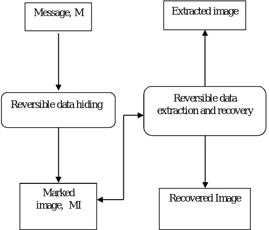
The general approach of reversible data hiding is shown in following fig
Reversible data extraction and recovery
Recovered Image Extracted image
Reversible data hiding Message, M
Technology (IJRASET)
Data Hiding
Here first take original image (host image HI) this is sender part of data hiding scheme. The embedded message M is a binary sequence. Transformation is applied, which is based on the properties of a histogram in a difference image and it is used to create the free space for hiding the embedded message M. During the hiding phase, the embedded message M is hidden in the difference image by using the proposed histogram modification process. Later, the marked image is obtained through the inverse transformation. In the receiver part, the receiver can also use the transformationfor extracting the included (embedded) message and reverse the marked image to its original. it has three part creating the histogram, the hiding part, and the extracting and reversing part.
II. LITURATURESURVEY
Min Wu and Bede Liu et al.(2004) give the concept of Data Hiding in Binary Image for Authentication and Annotation. Here uses binary images like text signature, figure and hides data in it. Only focus on flappable pixels of binary image to include data and hides it. Changing low-level features, flipping a black pixel to white or vice versa in binary images. Annotation is used with embedded data and authentication is used with extraction of this data.
Zhicheng Ni, Yun Q. Shi et al.(2008) proposed Robust Lossless Image Data Hiding Designed for Semi-Fragile Image Histogram
shifting and modificatio
Marked image
(MI)
Message (M)
Extracting and removing embedded message Original
Image (HI)
Creating histogram of
deference image
Recovering image and
Technology (IJRASET)
Authentication. They identifying a robust statistical quantity and employing it to embed data, differentiating the bit-embedding process based on the pixel group’s distribution characteristics, and using error correction codes and permutation scheme, this achieved both losslessness and robustness and applied to many images. They show that the data embedding capacity and the robustness of the proposed lossless data hiding scheme. against compression are acceptable for many applications, including semi-fragile image authentication. it has been successfully applied to authenticate losslessly compressed JPEG2000 images, followed by possible transcoding.
Wei-Liang Tai, Chia-Ming Yeh, and Chin-Chen Chang et al.(2009) Focuses on reversible data hiding based on histogram modification. Here exploit a binary tree structure to solve the problem of communicating pair of peak point. And distribution of pixel difference is used to hide data while keeping the distortion low also adopt a histogram shifting technique to prevent overflow and underflow.
Yongjian Hu, Heung-Kyu Lee and Jianwei Li (2009) “DE-Based Reversible Data Hiding With Improved Overflow Location Map” here examined and ensure the lossless recovery of the original image and only embed information bits into predicted errors that do not cause the overflow/underflow of image gray levels. In other words, the pixel value reconstructed from the embedded predicted error does not exceed the integer range for an8-bit image. The embedding capacity versus compressed (overflow) location map length curve and the embedding capacity versus image quality curve evaluate the performance. In this paper, investigated the problem of the overflow location map, which is an important issue in DE-based reversible data hiding. Here overflow location map depends on the payload. Unlike other (overflow) location maps, it contains two types of overflow locations: one from embedding and the other from shifting.
Xinpeng Zhang (2011) proposed Reversible Data Hiding for Encrypted Image in this encrypting the entire data of an uncompressed image by a stream cipher, the additional data can be embedded into the image by modifying a small proportion of encrypted data. In this proposed the reversible data hiding scheme for encrypted image with a low computation complexity, which consists of image encryption, data embedding and data extraction/ image-recovery phases. A data is entirely encrypted by a stream cipher in an uncompressed original image using encryption key to produce an encrypted image, and then a data hider embeds additional data into the encrypted image using a data-hiding key though he does not know the original content. With an encrypted image containing additional data, a receiver may firstly decrypt it using the encryption key, and the decrypted version is similar to the original image. According to the data-hiding key, he can further extract the embedded data and recover the original image from the decrypted version.
Xiaolong Li, Bin Li, Bin Yang, and Tieyong Zeng (2013) give General Framework to Histogram-Shifting-Based Reversible Data Hiding. in this introduce shifting and embedding functions here dividing the host image into non overlapping blocks such that each block contains n pixels and then n-dimensional histogram is generated and embedding is done by modifying the resulting n -dimensional histogram
Kede Ma, Weiming Zhang, Xianfeng Zhao (2013) Reversible Data Hiding in Encrypted Images by Reserving Room Before Encryption(RRBE) in this Experiments first reserves enough space on original image and then encrypted it with the encryption key. The data extraction and image recovery are identical to that of Framework VRAE. in this follows the idea that first losslessly compresses the redundant image content and then encrypts it with respect to protecting privacy. RRBE consists of four stages: generation of encrypted image, data hiding in encrypted image, data extraction and image recovery. The reserving operation in this experiment is a traditional RDH approach. This method can embed more than 10 times as large payloads for the same acceptable PSNR (PSNR=40 dB) as compared with the other methods for practical applications.
Zhenxing Qian, Xinpeng Zhang, and Shuozhong Wang (2014) Reversible Data Hiding in Encrypted JPEG Bitstream the proposed method aims are to encrypting a JPEG bitstream into a properly organized structure, and embedding a secret message into the encrypted bitstream by slightly modifying the JPEG stream. The secret message bits are encoded with error correction codes to achieve a perfect data extraction and image recovery. The encryption and embedding are controlled by encryption and embedding keys respectively. Here receiver has both keys to extract the secret bits and original bitstream perfectly recovered. In case the receiver only has the encryption key, he/she can still decode the bitstream to obtain the image with good quality without extracting the hidden data. When the embedding key is absent, the original image can be approximately recovered with satisfactory quality without extracting the hidden data. The proposed framework is also applicable on to JPEG-LS and JPEG 2000 with slight modification of the encryption and embedding schemes according to the respective coding-decoding algorithms. watermarking schemes for encrypted and compressed images is not done by this experiment.
Technology (IJRASET)
Modification this experiment proposed an improved histogram modification reversible data hiding algorithm using multiple scanning techniques. it have two stages: encoding the payload within an image to produce the cover image and decoding the cover image to retrieve the payload and the original image. The scanning techniques that we use are a horizontal, vertical, and diagonal scanning technique. In this used 4 × 4 image horizontal scanning technique. Experimental results indicate that our algorithm provides on average a 1.12 bpp payload capacity with 30dB PSNR.
Hao-Tian Wu et al. (2015) proposed Reversible Image Data Hiding with Contrast Enhancement for digital images. Instead of trying to keep the PSNR value high, the proposed algorithm enhances the contrast of a host image to improve its visual quality. The highest two bins in the histogram are selected for data embedding. The proposed algorithm was implemented on two sets of images to demonstrate its efficiency. In this achieves image contrast enhancement by RDH. Furthermore, the evaluation results show that the visual quality can be preserved after a considerable amount of message bits have been embedded into the contrast-enhanced images, even better than three specific MATLAB functions used for image contrast enhancement.
Xin Liao and Changwen Shu (2015) propose a novel method of evaluating the complexity of image blocks, which considers multiple neighboring pixels according to the locations of different pixels. Experiments show that the method can reduce average extracted-bit error rate when the block size is appropriate. In order to further reduce the error rate, here a new calculation of block complexity is proposed. The complexity of image blocks can be estimated by calculating the absolute mean difference of pixels and their neighboring pixels A new function is used to estimate the complexity of each image block and increase the correctness of data extraction/image recovery, i.e., decrease the average extracted-bit error rate. The data embedding ratio is also considered when data embedding and data extraction/image recovery are performed.
Chin-Feng Lee, Chin-Chen Chang, Pei-Yan Pai, and Chia-Ming Liu (2015) described “An Adjustable and Reversible Data Hiding Method Based on Multiple-base Notational System without Location Map” In this some cover pixels are modified to avoid the overow / underow problem when the secret data are embedded. The secret data are embedded using a multiple-base notational system in the embedding procedure and the receiver can restore the original cover image from the stego-image without the requirement of a location map while the secret data are extracted. in this the achieves a embedding capacity and satisfactory visual image quality.
Neethu Thomas and Shiney Thomas (2016) experiment is based on PPVO (pixel-based pixel value-ordering) and prediction-error expansion. The work in named as “A Low Distortion Reversible Data Hiding Technique using Improved PPVO Predictor”. In this experiment Predictions are made in a block-by-block manner and a pixel-based pixel value ordering (PPVO) is slightly modified Unlike PVO, IPVO and PVO-K, PPVO calculates predictions of a pixel in a pixel-by-pixel manner.
III. RELATED WORK
Some literatures on data hiding related works is scant, some researches present recently that is Fridrich et al. [8] proposed invertible watermarking method to authenticate images in the JPEG domain. They used an order-2 function, which is an inverse function, to modify the quantization table to enable lossless embedding of one bit per DCT coefficient. For uncompressed image formats, Fridrich et al. [9] presents RS scheme which is a lossless data hiding scheme with high payload by embedding bits into the status of groups of pixels.
Later Tian [10] proposed an interesting scheme for reversible data hiding called difference expansion (DE), embedded messages in the resulting high-pass band of the Haar wavelet decomposition. Alattar [11] proposed a reversible watermarking scheme for color images by using the DE of a generalized integer transform (GIT). Kamstra et al. [12] improved the DE scheme by using sorting to increase the efficiency of lossless compression. Thodi et al. [13] used a histogram shifting technique to embed the location map for solving the location map problem generated by DE, and also proposed a prediction-error expansion approach that better exploited the correlation inherent in the neighborhood of a pixel than the DE scheme. Celik et al. [14] proposed a lossless generalized-LSB data embedding scheme that is a generalization of the LSB-embedding method, called G-LSB. They transformed the embedded message using a variant of arithmetic encoding, then hidden the interval number in a cover image. Ni et al. [15] used the zero point and peak point of an image histogram to hide message and achieved reversibility. Their idea is very simple and causes only slight distortion with low complexity; however, their experimental results demonstrate that its largest hiding capacity is only about 5 kb when the test image is “Lena” (512×512×8 bits). Chang et al. [16, 17] presented a reversible data hiding technique for lossy compression domain side match vector
Technology (IJRASET)
approximate code words for conveying embedded messages. Hu et al. [18] proposed a reversible visible watermarking scheme for a new application scenario where the visible watermark servers as a tag or ownership identifier. In 2007, Lee et al. [19] proposed a high capacity reversible image watermarking scheme based on integer-to-integer wavelet transforms.
IV. METHODOLOGY
A. Methodology
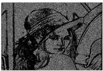
[image:7.612.246.410.144.257.2]Here applying peak point of histogram of Lena’s gray scale image to generate inverse transformation (inverse transformation value T1^-1) for creating free space in image. Peak point value is taken 155 from fig d. If peak point of image histogram not provide max hiding capacity it extended until space provide for large embedded information. The peak point value corresponding to the grayscale value and the grayscale value corresponding to the maximum number of pixels in the histogram of the given image. The main aim is to find the max. peak point value from deference image of Lena given below to increase hiding capability to greatest degree possible.
Fig a: Gray scale image of “LENA”
Fig b: Histogram of Gray Scale Image of “LENA”
Pixels
Peak point
N
u
mb
e
r
of
P
ix
e
ls
val
u
[image:7.612.199.442.339.712.2]Technology (IJRASET)
Fig d: Histogram Difference image of “LENA” with peak point of 155 Data Hiding
Y
N
Testing overflow and
underflow?
Recording PSNR and bpp value Image
Layer=5? Message M
Creating difference image of marked image MI (Marked Image)
Modify Histogram
Perform layer by layer data hiding with message M
Creating histogram of difference image Create histogram of grayscale
image
Create difference image (DI)= (original image-grayscale image)
Create histogram of difference image
Shift histogram Create grayscale of original
image Start
Load Host image
Plot graph between PSNR and BPP Stop
N
Y
Technology (IJRASET)
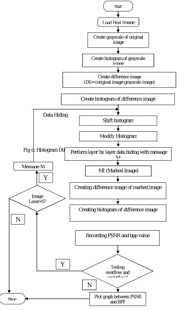
B. Flow Chart of Methodology
Below Fig shows the flowchart of our proposed reversible data hiding. Here message M is a binary sequence which included in image by sender. T is a transformation, which is depends on difference image’s histogram. This T is used to create the free space in image for hiding the embedded message M. By the inverse transformation T^−1 the MI is obtained. Receiver uses the same transformation T to extract the embedded message which is hidden and reverse the MI to its original.
This mechanism has three parts reating the histogram
Hiding message PSNR calculation
C. Creating the Histogram
This create large free space for data hiding. GCI(i,j),PQ pixel in size for gray scale image, for difference image 1)
-PX(Q j),
DI(i, pixel in size, generated from host image (HI) by using following formula:- 2) -Q <= j <= (0 1) -P <= i <= (0 where 1) + j HI(i, -j) GCI(i, = j) DI(i,
D. Hiding message
Step 1: Divide the original cover image into blocks
A
B
in size. Generate a difference image DI (i, j) of size A×(B−1) for each block by using following formula:1 -B) (A N) (M <= b <= 0 2, -B <= j <= 0 and 1, -A <= i <= 0 Where 1)] + j (i, b H -j) (i, b [H = j) i, DI(
163 156 164 160 162 160 159 160 161 162 160 156 160 159 157 158
7 8 4 2 1 1 1 2 4 1 2 1
8 9 5 3 1 1 1 3 5 0 3 1 7 8 6
3 2 1 2 3 5 0 3 1
Table: difference image of ‘LINA’
MI Table: 4x4 block of gray scale
images of “LINA”
Table: modified
difference image Table: hidden
difference image
Hb DIb
Technology (IJRASET)
Table: marked image
Step 2: Generate the histogram of the difference image DIb and record the peak point Ppb for each block.
Step 3: If the pixel value DIb(i, j) of block b is larger than the peak point Ppb of block b, change the pixel value DIb(i, j) of block b
to DIb(i, j)+1. Otherwise, the pixel value DIb(i, j) remains unchanged.
The modification principle is defined as
otherwise j) (i, b DI b Pp > j) (i, b DI if 1 + j) (i, b DI ) , ( 'b i j
DI 1 B A N M b 0 & 2 -B j 0 1, -A i 0
for
Where Ppbis the peak point of block b.
Step 4: For the modified difference image DIb, peak point Ppb values same as the pixels have grayscale values, can be modified as
follows to hide embedded message bit msg :
otherwise j) (i, b DI' b Pp > j) (i, b DI' if msg + j) (i, b DI' ) , ( "b i j DI 1 B A N M b 0 & 2 -B j 0 1, -A i 0
for
Where Ppbis the peak point of block b and msg ∈ {0, 1}.
Step:5 here using the hidden difference image(HDI) of original image and original image (OM) to form or construct the marked image(MI) by performing inverse transformation T-1 as following. The inverse operation is expressed for the first two pixels in each row as following:
otherwise (i,0) b DI" + (i,1) b HDI (i,1) b HDI > (i,0) b HDI if (i,0) b HDI ) 0 , (i b MI 1 B A N M b 0 and 1, -A i 0
for
The inverse operation is defined for any residual pixels is as
otherwise 1) -j (i, b DI" -1) -j (i, b MI j) (i, b HDI 1) -j (i, b HDI if 1) -j (i, b DI" 1) -j (i, b MI ) 0 , (i b MI 1 B A N M b 0 and 2 2 1, -A i 0
for
j B
In this phase we approaches multiple layers of hiding data that means in an image different layer of images is used to hide data and also random large integer data is used to hide.
E. PSNR Calculation
The PSNR stands for peak signal noise ratio of an image is generally used to measure the quality of image or the evaluating image quality. Here we also adopt PSNR for marked image to measure the quality of image generated by our proposed scheme and
164 156 165 160 163 160 159 161 160 163 159 155 159 159 155 156
Technology (IJRASET)
investigate the lower bound of the quality of image of the marked image. Assume that at the first level of data hiding and the block size is set to 4×4 and all message bits are 1 in worst case then in deference image all pixel values must be added by 1. From left to right for each row of each block, the distortion, which is the pixel difference between the original image and the marked image, forms an arithmetic sequence “0”, “1”, “2”, and “3”, respectively. Therefore, the distortion in each block can be depicted as
k
k
0
3
4
where (k=pixel of MI - pixel of original image) that means k is the pixel difference between the marked image andthe original image. So the mean squared error (MSE) is
)
16
0
3
4
(
2
k
k
MSE
.Thus the lower bound of PSNR for the marked image can be calculated as:
23
.
45
)
255
(
log
10
)
(
2 10
MSE
dB
PSNR
the lower bound of PSNR is about 45.23 dB in our first-level hiding in experiments.
F. Computational Complexity
In our proposed scheme all the process is in the spatial domain. The computational complexity of our proposed scheme is low because it has not any frequency domain transforms such as DCT (discreet cosign transform), DWT, and so on. The operation requires in this scheme for generating the histogram of original image and also the histogram of difference image for a cover image, determining peak point from the histogram, hiding messages, and doing the inverse transformation this all process is done in the spatial domain. Thus, the execution time of the proposed scheme is possibly minimized that means short execution time is taken to execute. Let’s assume that the block size of original image is A × B, and there are mblocks in it and for each block, our proposed scheme needs to scan the whole block five times in the hiding phase because we take random data to hide so the computational complexity is O(5AB) and the total computational complexity is O(5ABm) because the whole image case is just layer by layer multiple repetition of single block. With a MATLAB programming software and Intel ® Pentium ® 2.10 CPU processor the total embedding time needed for the “Lena” image (512 × 512 × 8) is just 28.84 second for each 0.10 bpp.
G. Possible “Overflow And Underflow” Condition PreventionOverflow and underflow is the basic condition possible to occur in marked image at the time of hiding massage and the time of extracting data from marked image. it is done in some pixels of image gray scale value, that means the grayscale values of some pixels in the marked image may exceed the upper bound which is 255 for an eight-bit grayscale image or the lower bound which is 0 for an eight-bit grayscale image. This is possibly done when we apply the addition or subtraction operations which are perform on pixel values that are close to 255 or 0.
To overcome this problem overflow and underflow, the modulo operation gives by Goljan et al. [5] and Honsinger et al. [20] was adopted to avoid this overflow or underflow problem occurs in our proposed scheme.
For the marked image, we define each pixel (i,j) b MI as 256 mod ) , ( ) ,
(i j MIb i j b
MI
Other side the marked image MIb(i, j)=255, was derived from 255 or −1 must be distinguished. Considering the characteristics of an
image, no tremendous variations exist for adjacent pixels. Therefore, in case of a significant difference between MIb(i, j–1) and
MIb(i, j), MIb(i, j) was conducted by a modulo operation. Two evaluations are presented here to restore the original value of MIb(i, j)
after the modulo operation is performed. If MIb(i, j–1) is larger than TH1, MIb(i, j) is restored as
otherwise j) (i, b MI 2 TH | j) (i, b MI -1) -j (i, b MI | if 256 + j) (i, b MI j) (i, b MI
where TH1 and TH2 are threshold values. If MIb(i, j–1) is smaller than TH1, MIb(i, j) is restored as
Technology (IJRASET)
V.RESULTANDDESCUSSION
A. Experimental Result
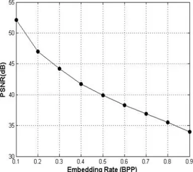
In this section we show three test images with its difference images and histogram of difference image and basis of these image we evaluate the relationship between PSNR (Db) and bpp. In our proposed method defines the relation between PSNR and bpp and also plotting a graph between it for evaluation.
Fig: 1 gray scale image of LENA
Fig: 2 histogram of gray scale image of LENA
Technology (IJRASET)
Fig: 4 histogram of difference image1 of LENA
Fig: 5 difference image2 of LENA (51.5Db with 0.2 bpp)
Technology (IJRASET)
Fig: 7 final difference image of LENA (37Db with 0.9 bpp)
Fig: 8 histogram of final difference image of LENA
Technology (IJRASET)
Fig: 10 gray scale image of SAILBOAT
Fig: 11 histogram of gray scale image of SAILBOAT
Fig: 12 difference image1 of SAILBOAT (53Db with 0.1 bpp)
Technology (IJRASET)
Fig: 13 histogram difference1 image of SAILBOAT
Fig: 14 final difference image of SAILBOAT (32Db with 0.9 Bpp)
Technology (IJRASET)
Fig: 16 Graph between PSNR (Db) and embedding rate (Bpp) of SAILBOAT
Fig: 17 gray scale image of PEPPERS
Technology (IJRASET)
Fig: 20 Histogram of difference image of PEPPERS
Technology (IJRASET)
Fig: 22 Histogram of final difference image of PEPPERS
Fig: 23 Graph between PSNR (Db) and embedding rate (Bpp) of PEPPERS
Table2: SAILBOAT
Srno Image name(fig) PSNR bpp
1 Fig12 53 0.1
2 Fig14 32 0.9
Table3: PEPPERS
Srno Image name(fig) PSNR bpp
1 Fig 19 52.5 0.1
[image:19.612.202.394.274.446.2]2 Fig 21 34.3 0.9
Table 1: LENA
Srno. Image name(fig) PSNR bpp
1. Fig3 54 0.1
2. Fig5 51.3 0.2
[image:19.612.219.392.490.702.2]Technology (IJRASET)
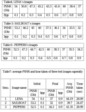
Table4; LENA’s imagesPSNR (Db)
54 50.8 47.3 45.2 43.3 41.6 40 38.4 37
[image:20.612.161.454.76.456.2]Bpp 0.1 0.2 0.3 0.4 0.5 0.6 0.7 0.8 0.9
Table 5: SAILBOAT’s images PSNR
(Db)
53.2 46.2 45 40 37.3 36.1 34 33.5 32
bpp 0.1 0.2 0.3 0.4 0.5 0.6 0.7 0.8 0.9
Table 6 : PEPPERS’s images PSNR
(Db)
52.5 47.3 44.7 42.5 40 38.3 37 35.5 34.3
bpp 0.1 0.2 0.3 0.4 0.5 0.6 0.7 0.8 0.9
Table7: average PSNR and time taken of three test images saperatly
Srno. Image name
Initial Final Avg
PSNR (Db)
Time taken (sec) PSNR
(Db) bpp
PSNR (Db) bpp
1 LENA 54 0.1 37 0.9 44.19 28.09
2 SAILBOAT 53.2 0.1 32 0.9 39.7 24.47 3 PEPPERS 52.5 0.1 34.3 0.9 41.35 28.99
Technology (IJRASET)
estimated execution time (time taken to perform operation) of three test images in this for LENA’s images maximum PSNR is 54Db in 0.1 bpp (bit per pixel) and minimum PSNR is 37Db in 0.9 bpp and time taken is 28.09 sec. Similarly for the SAILBOAT max(PSNR) is 53.2Db and min(PSNR) is 32Db, time taken 24.47 and for the PEPPER max(PSNR) is 52.5Db and min(PSNR) is 34.3Db, time taken 28.99 sec. The average PSNR value for LENA is 44.19Db similarly The average PSNR value for SAILBOAT is 39.70Db and The average PSNR value for PEPPER is 41.35Db.
The comparative results for hiding capacity of data in image among different authors in term hiding capacity in bpp verses image quality in PSNR are as MU Celik (G-LSB)[14] generalized least significant bit (G-LSB), the min PSNR value is 32 when maximum bpp is 0.7 and also the maximum PSNR is 51 when minimum bpp is 0.02. The second aurther J. Tian[10] DE (deference expansion). The max(PSNR) is 45 when min(bpp) is 0.15 and min(PSNR) is 16 when max(bpp) is 2. According to the third aurther CHIA-CHEN LIN max(PSNR) is 50 when min(bpp) is 0.25 and also the min(PSNR) is 27 when max(bpp) is 2.31. that means our proposed scheme is performed better in hiding the data in image and calculating the PSNR value in each bpp.
V. CONCLUSION
The different type various method used by different author for data hiding in image. Different method have different levels of hiding capacity. Result of the third author balanced the hiding capacity (in bpp) and image quality (in PSNR) and distortion on image is minimized.
When bpp value is minimum then PSNR value is maximum and when bpp is maximum then PSNR is minimum. From the above comparison we conclude that when bpp is increases 0.1 bits then some PSNR loss is obtained. ∆b is change in bits per pixel (bpp).
∆PSNR is change in PSNR value in different level. Here change in PSNR is finding by the formula )
min( )
max(PSNR PSNR
PSNR
.
For finding percentage loss in PSNR in deferent levels, by formula
100 ) max(PSNR PSNR .For LENA’s image ∆PSNR=54-37=17Db so the %PSNR loss = 100 54 17
= 31.48%.
For SAILBOAT’s image ∆PSNR=53-32=21Db so the %PSNR loss = 100 53 21
=39.62%.
For PEPPER’s image ∆PSNR=52.5-34.3=18.2Db so the %PSNR loss = 100 5 . 52 2 . 18
= 34.67%.
The % distortion in average PSNR is 4.9%, 4.41%, and 4.59% that is minimum in LENA, SAILBOAT and PEPPER’s image respectively.
It is concluded that in our proposed scheme the minimum distortion in average level where data hiding is maximum and PSNR loss value is also average and also we conclude that the PSNR value is inversely proportional to the bpp of image because from our experimental graph shows if bpp is minimum the PSNR value is maximum and if bpp is maximum the PSNR value is minimum that means when bpp increases then PSNR value decreases.
In other word we say that if we increase the size of embedded message then the PSNR decreases and distortion in image occurs.
REFERENCES
[1] M. Wu, B. Lin, Data hiding in image and video: part I—fundamental issues and solutions, IEEE Trans.Image Process. 12 (6) (2003) 685–695. [2] M. Wu, H. Yu, B. Liu, Data hiding in image and video: part II—designs and applications, IEEE Trans. Image Process. 12 (6) (2003) 696–705.
[3] S.S. Maniccam, N.G. Bourbakis, Lossless compression and information hiding inimages, Pattern Recognition 37 (3) (2004) 475–486.C.-C. Chang, C.-C. Lin, C.-S. Tseng, W.-L. Tai, Reversible hiding in DCT-based compressed images, Inf. Sci. 177 (13) (2007) 2768–2786.
[4] M. Goljan, J. Fridrich, R. Du, Distortion-free data embedding, in: Proceedings of the Four Information Hiding Workshop, [5] Lecture Notes in Computer Science,vol. 2137, Springer, NewYork, April 25–27, 2001, pp. 27–41.
[6] J. Fridrich, M. Goljan, R. Du, Invertible authentication Watermark for JPEG images, in: Proceedings of International Conference on Information Technology: Coding and Computing, Las Vegas, Nevada, April 2001, pp. 223–227
[7] J. Fridrich, M. Goljan, R. Du, Lossless data embedding for all image formats, in: Proceedings of SPIE Photonic West, Electronic Imaging 2002, Security and Watermarking of Multimedia Contents, vol. 4675, San Jose, California, January,2002, pp. 572–583.
Technology (IJRASET)
January 2001, pp.197–208.[9] J. Fridrich, M. Goljan, R. Du, Lossless data embedding—new paradigm in digital watermarking, nEURASIP J. Appl. Signal Process. 2002 (2) (2002 185–196. [10] J. Tian, Reversible data embedding using a differenc expansion, IEEE Trans. Circuits Systems VideoTechnol 13 (8) (2003) 890–896
[11] A.M. Alattar, Reversible watermark using the difference expansion of a generalized integer transform, IEEE Trans. Image Process. 13 (8) (2004) 1147–1156. [12] L. Kamstra, H.J.A.M. Heijmans, Reversible da embedding into images using wavelet techniques an sorting, IEEE Trans. Image Process. 14 (12) (2005)
2082–2090.
[13] D.M. Thodi, J.J. Rodríguez, Expansion embeddintechniques for reversible watermarking, IEEE Trans.Image Process. 16 (3) (2007) 721–7 [14] M.U. Celik, G. Sharma, A.M. Tekalp, E. Saber, Losslesseneralized-LSB data embedding, IEEE Trans. Imag Process. 14 (2) (2005) 253–266.
[15] Z. Ni, Y.-Q. Shi, N. Ansari, W. Su, Reversible data hiding, IEEE Trans. Circuits Systems Video Technol. 16 (3) (2006) 354–3 C.-C. Chang, W.-L. Tai, M.-H. Lin, A reversible data hiding scheme with modified side match vector quantization, in: Proceedings of the IEEE 1 International Conference on Advanced Informat Networking and Applications, vol. 1, Taipei, Taiwan, March 2005, pp. 947-+-952.
[16] C.-C. Chang, W.-L. Tai, C.-C. Lin, A reversible data hiding scheme based on side match vector quantization IEEE Trans. Circuits Systems Video Technol. 16 (10) (2006) 1301–1308.
[17] Y. Hu, B. Jeon, Reversible visible watermarking lossless recovery of original images, IEEE Trans. Circuits Systems Video Technol. 16 (11) 1442 14 [18] S. Lee, C.D. Yoo, T. Kalker, Reversible image