Technology (IJRASET)
IR Sensor Based Squats Detection of Railway
Track using Robot
Sindhu1, Veeresh Pujari2, Dr.Basawaraj Gadgay3
1PG student, 2Project Guide (DEPT. VLSI DESIGN AND EMBEDDED SYSTEMS), 3 PG co-ordinator/ Special Officer RO VTU PG center KALABURGI.
Abstract: This paper proposes the design of crack finding robot for finding cracks in the railway tracks. Here the LPC2148 microcontroller is interfaced with Robot, Global Positioning System (GPS), Liquid Crystal Display (LCD) and Crack Sensor. The IR
sensor senses the voltage variations from the crack sensor and then it gives the signal to the microcontroller. The microcontroller checks the variations in the voltage of the measured value with the threshold value. If the microcontroller detects the crack in the railway track, it immediately gets the exact location information using Global Positioning System (GPS) and Global System for mobile (GSM) and sends that location and crack information to the control section. And the control section displays the exact location that is latitude and longitude value in map by using .NET Software. The Liquid Crystal Display (LCD) is used to display the current status of the system.
Keywords-: Global Positioning System (GPS), Liquid Crystal Display (LCD) , Control section, Global System for mobile (GSM).
I. INTRODUCTION
The Transportation of train always depends on the railway tracks (rails) only. If there is a track in rails, it creates the biggest problem. Most of the accidents in the train are caused due to cracks in the railway tracks, which cannot be easily identified by our naked eyes. Also it takes time to rectify the problem, we are using the crack detector robot, which will detects the crack in the rails and gives alarm. A robot is an apparently human automation, intelligent and obedient in nature but an impersonal machine. The robots have started to employ a degree of Artificial Intelligence (AI) in their work and many robots required human operators, or precise guidance through their missions. Slowly, robots are becoming more autonomous. In the advanced system, the robot designed for finding the crack in the railway track with the help of sensor and the exact location of the railway crack information is send to the control section using Global System for mobile (GSM) and Global Position System (GPS) technology.
[image:2.612.57.258.473.620.2] [image:2.612.301.535.476.621.2]
Fig 1:squats in railway track Fig 2:squats on railway track
II. LITERATURE SURVEY
need for improved detection and maintenance methods to treats such defects at reduced costs, and for better track design to avoid or retard occurrence of them. In [3] the paper aims at studying the interaction between an elastic wheel set and ballasted track due to the polygonal wheels. The wheel set is considered a Timoshenko beam with attached rigid-bodies as axle boxes, wheels and brake discs. The track model includes a new model of the rail periodic support consisting in two threedirectional Kelvin-Voigt systems for the rail pad and the ballast. The main features of the wheel/rail vibration due to the polygonal wheel are analyzed via a new approach of the Green’s matrix of the track method. In [4] the prediction of
impact forces caused by wheel flats requires the application of time-domain models that are generally more computationally
demanding than are frequency-domain models. In this paper, a fast time-domain model is presented to simulate the dynamic interaction between wheel and rail, taking into account the non-linear processes in the contact zone. In [5] The development of an efficient Weigh-In-Motion (WIM) system, with the aim of estimating the axle loads of railway vehicles in motion, is quite interesting from both an industrial and academic point of view. Such systems, with which the loading conditions of a wide population of running vehicles can be verified, are very important from a safety and maintenance perspective. In [6] AC bridge techniques commonly used for precision impedance measurements have been adapted to develop an eddy current sensor for rail defect detection. By using two detected coils instead of just one as in a conventional sensor, we can balance out the large baseline signals corresponding to a normal rail. In [7] Today therailway are facing exposure of heavy loads, higher speeds
and a very dense traffic. The development of testing methods for the rails inspection trains has became necessary to match the modern needs for a fast detection and detailed classification of defects .Nowadays, to guarantee the safe operation of rail traffic non-destructive inspection techniques with combined ultrasound and eddy current testing methods are used to detect damages on rails. In [8] Eddy current technique has been developed to enable identification and evaluation of rolling contact fatigue (RCF) defects. The ultrasound technique is aimed at measurements in the rail bulk volume, which are not feasible using through eddy current technique. In [9] Corrugation can be detected by simpler measurement with this method using a microphone in the
cabin. It was also confirmed that the extent of corrugation can also be diagnosed by this method, in an experiment using a commercial railway line. In [10] Detection of rails defects are major issues for all rail workers around the world. Some of the most defects include worn rails, welding problems, internal defects, corrugations and initiated problems such as surface cracks, head checks, squats. If undetected or untreated these defects can lead to rail breaks and derailments.
III. PROPOSED DESIGN METHODOLOGY
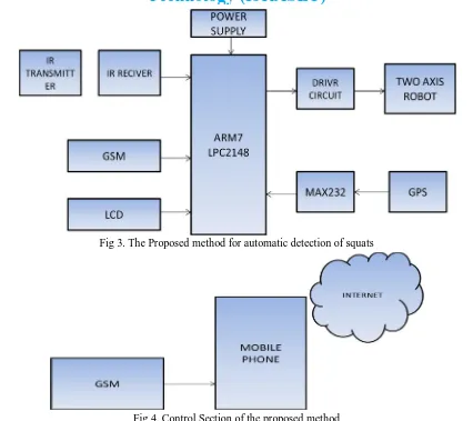
The proposed method for the automatic detection of squats in railway track is illustrated in fig 3. The supply of 5Volt DC is given to the system which is converted from 230Volt AC supply. Firstly, the step down transformer will be used here for converting 230Volt AC into 12Volt AC. The microcontroller will support only the Direct Current supply, so the Alternating Current supply will be converted into DC using the bridge rectifier. The output of rectifier will have some ripples so we are using the 2200uf capacitor for filtering those ripples. The output from the filter which is given to the 7805 voltage regulator which will convert the12Volt Direct Current into 5Volt DC. The output from the regulator will be filtered using the 1000uf capacitor, so the pure 5Volt DC is getting as the output from the power supply unit. Here we can use the LPC2148 microcontroller which will be capable of getting the supply of 5Volt DC so we have to convert the 230Volt AC supply into 5Volt DC supply. The microcontroller unit is used to detect the crack in the track by using the IR transmitter and IR receiver then the corresponding information is send to the control section using GSM , the movement of robot also controlled by the controller. The display unit is mainly achieved by the 16X2 LCD. A liquid crystal display (LCD) is a flat panel display, an electronic visual display, or video display that uses the light modulating properties of liquid crystals (LCs). LCs do not emit light directly. In this project LCD is used to display sensor value. In this work, GSM is the communication unit is used to transmit the sensor (IR transmitter and receiver) value to the monitoring section. Software is used to compile the coding of the desired application for the corresponding embedded system. GPS stands for Global Positioning System (GPS). It is a space-based on Global navigation satellite system. It provides position, and navigation to worldwide users on a continuous basis in all weather i.e. day and night, anywhere on the Earth. GPS is made up of 3 parts: between 24 and 32 satellites orbiting the Earth, 4 controls and monitoring stations on the Earth. GPS satellites will broadcast signals from space that are used by help of GPS receivers to provide two-dimensional location (latitude, and longitude)
.
Technology (IJRASET)
[image:4.612.110.504.87.283.2]Fig 3. The Proposed method for automatic detection of squats
Fig 4. Control Section of the proposed method
IV. HARDWARE IMPLEMENTATION
A. Power Supply
The power supply must deliver a constant output regulated supply. A 230V/0-12V (1mA) transformer is used for this purpose. The primary of the transformer is connected through switch for protection. The secondary is connected to the diodes to convert 12V AC to 12V DC voltage. And filtered by the capacitors, which is further regulated to +5v, by using IC 7805.
B. LCD
The alphanumeric 16character X 2line LCD requires 8data lines and also 3 control signals and they are interfaced to 3664.By using 2 ports, port 0&3 data pins are connected to LCD as data bus. Port0 can be basically used as I/O port i.e. it can be programmed as an input or as an output port.
C. IR Sensor
The IR sensor senses the voltage variation from the cracks and gives the signal to the microcontroller. The microcontroller checks the voltage variations of the measured value with the threshold value
D.MAX232
The Global Positioning System (GPS) is a U.S. space-based Global Navigation Satellite System. It provides reliable positioning, navigation, and timing services to worldwide users on a continuous basis in all weather, day and night, anywhere on or near the Earth. GPS satellites broadcast signals from space that are used by GPS receivers to provide three-dimensional location (latitude, longitude, and altitude) plus the time. The basic idea is to gauge GPS inaccuracy at a stationary receiver station with a known location. Since the DGPS hardware at the station already knows its own position, it can easily calculate its receiver's inaccuracy. In general, access to this correction information makes GPS receivers much more accurate than ordinary receivers.
F. Driver Circuit
L293D is a dual H-Bridge motor driver, So with one IC we can interface two DC motors which can be controlled in both clockwise and counter clockwise direction and if you have motor with fix direction of motion the you can make use of all the four I/Os to connect up to four DC motors. L293D has output current of 600mA and peak output current of 1.2A per channel. Moreover for protection of circuit from back EMF output diodes are included within the IC. The output supply (VCC2) has a wide range from 4.5V to 36V, which has made L293D a best choice for DC motor driver
G.GSM
Global System for Mobile Communications system is the most popular standard for mobile telephony systems in the global. The GSM is one the wireless networks which has low power and low cost communication device.
V. . EXPERIMENTAL SETUP AND RESULT
A. In the advanced system, the robot is designed for finding cracks in the railway tracks. Here the microcontroller is interfaced with Robot,. The IR sensor senses the voltage variations from the crack sensor and then it gives the signal to the microcontroller. The microcontroller checks the variations in the voltage of the measured value with the threshold value. If the microcontroller detects the crack in the railway track, it immediately gets the exact location information using Global Positioning System (GPS) and Global System for mobile (GSM) and sends that location and crack information to the control section. And the control section displays the exact location that is latitude and longitude value in map by using .NET Software.
Technology (IJRASET)
Fig 7: there is no crack Fig 8: Left crack is detected
Fig 9 :In fone msg is come Fig 10 :Exact location of crack
VI. CONCLUSION
In this paper, the design of crack finding robot for finding cracks in the railway tracks. Here the microcontroller is interfaced with Robot, GSM, Global Positioning System (GPS), Liquid Crystal Display (LCD) and Crack Sensor. The IR sensor senses the voltage variations from the crack sensor and then it gives the signal to the microcontroller. The microcontroller checks the variations in the voltage of the measured value with the threshold value. If the microcontroller detects the crack in the railway track, it immediately gets the exact location information using Global Positioning System (GPS) and Global System for mobile (GSM) and sends that location and crack information to the control section. The control section displays the exact location that is latitude and longitude value in map by using .NET Software. The Liquid Crystal Display (LCD) is used to display the current status of the system. The exact location of the crack in the track with can easily be identified with the help of Global Positioning System (GPS) and Global System for mobile (GSM).
REFERENCES
[1] ili Li, Rolf Dollevoet, Marija Molodova and Xin Zhao, "The validation of some numerical predictions on squats growth", September 15-18,Vol 271,PP.369-37 [2] M.Oregui 1, Z. Li 1, R. Dollevoet 2"Relating track parameter conditions to squat and corrugation initiation and growth"2010,15,pp.3519-3529
[3] Train Mazilu "Wheel and rail interaction due to the polygonal wheel",2011,vol D,pp.95-108 [4] A.Pieringer and w.Kropp"A fast time domain model for wheel/rail interaction"june 29, 2008.
[5] Mirko Ignesti, Alice Innocenti, Enrico Meli, Luca Pugi, Andrea Rindi "Development and Validation of Innovative Weighing in Motion Systems"2013, pp.763-768.
[6] Ze Liu1, Andrew D. Koffman, Bryan C. Waltrip, and Yicheng Wang, "Eddy Current Rail Inspection Using AC Bridge Techniques", 2013,118,pp.140-149 [7] Thomas Heckeli,Hans-Martin Thomas1,Marc Kreutzbrucki & Sven Ruhe, "High speed non destructive rail testing with advanced ultrasound and eddy current
Destruct. Testing Condition Monitoring, vol. 49, no. 6,