Designing of Multi (Dual) Band and Ultra-Wide
Band Microstrip Patch Antenna for Wireless
Applications
Nidhi1, Ajay Kumar Jaiswal2, Jagtar Singh3
1
M.Tech Student, 2,3Assistant Professor, ECE Department, N.C. College (Israna), Panipat
Abstract: This research paper presents a simple design consideration of Multi (Dual) band and Ultra-Wide Band (UWB) Microstrip antenna using a centrally loaded rectangular slot. An analytical study of the effects of different size and shapes of slots (cut) on the performance characteristic of UWB Microstrip antenna is presented. Insertion of slot and the changes in dimension of ground plane has a high impact on the behavior and parameter of the patch antenna. To improve the bandwidth of the patch antenna, proper insertion of slot on the planer patch structure has been used. In the paper a rectangular patch antenna carved on FR4 substrate is presented. Both the simulated and the measured result show the operation of the antenna in the entire UWB range. The proposed antenna will designed by using rectangular type defected patch i.e DMPS (Defected microstrip patch Structure) for particular feeding technique. The Paper will give a better understanding of design parameters of an antenna and their effect on return loss, S-Parameters, smith chart, radiation pattern, bandwidth, VSWR and resonant frequency. Finally simulation will be done by using design software HFSS13.0. This parametric study would be of a great interest in the designing of compact antennas for wireless communications operating in UWB.
Keywords: Multi (Dual) band, Ultra-wide band, Rectangular microstrip patch antenna, S-Parameters, smith chart, radiation pattern, bandwidth, VSWR, resonant frequency, HFSS13.0.
I. INTRODUCTION
UWB is one of the most interested wireless communication systems which can be used for monitoring, positioning, security, microwave imaging and various communication application. Due to its high gain, omni-directional radiation pattern, high data resolution, low complexity, inexpensive properties, it is becoming more attractive research phenomena for students and wireless communication. The antennas with ultra-wideband frequency have been broadly researched and developed after the declaration of the unlicensed bandwidth of 3.1 to 10.6 GHz as UWB by Federal Communication Commission (FCC) [1]. Printed slot type antennas are mostly accepted for UWB application. It is still a challenge to antenna designers to design a compact, cost effective, high gain ultra-wideband antennas.
In recent years, due to its various number of benefits including stable radiation pattern, high gain, low profile and inexpensive fabrication the printed microstrip slot antennas were significantly researched. For UWB applications numerous antennas were designed. Among them, one of the antenna requires a large ground plane that rises dimension. As a result, that is not included in microwave integration [2]. Various line feeding and waveguide feeding antennas were offered for UWB applications. For achieving the characteristics of wide impedance bandwidth monopole architectures are commonly used, such as elliptical, pentagon, rectangular, square, hexagonal, annular ring and circular ring antennas
Antenna is the most fundamental block of the wireless communication. Recently, the growth of wireless systems leads to a lot of innovations in the Microstrip antenna designs. Microstrip patch antenna has become an integral part of these devices working in ultra to super high frequency ranges. The patch and slot are the two parameters which affect the overall antenna’s performance. Microstrip patch antennas are useful in various applications having requirements like broader bandwidth, smaller in size, lighter in weight, lower in cost and compatibility with integrated circuits [1-2]. A variety of wireless communication engineering applications, such as wireless links, remote sensing, cellular mobile phones and internet are in extensive demand and have witnessed a tremendous growth recently. The microstrip antenna has narrow bandwidth of the order upto 5%. This low bandwidth is not useful for many wideband wireless applications. Previously published literature has reported several possible techniques to improve bandwidth of the microstrip antenna.
(MMICs). Due to these striking features, the researchers are having noteworthy attention towards microstrip antennas. Microstrip patch antennas are used in extensive range of applications such as in wireless communication and biomedical diagnosis [3]. In recent years, the widespread proliferation of wireless communication has augmented the demand for compact broadband antennas for handheld devices, satellite systems, etc. But it has a disadvantage of producing narrow bandwidth and low gain. To overcome the inherent limitation, many techniques such as probe fed antenna, stacked shorted patches, patch antenna with thick substrate electrically and slotted patch antenna have been planned and investigated[3].
II. ANALYSIS OF ANTENNA
[image:3.612.160.462.225.383.2]The length of the patch is denoted by L and width of the patch is denoted by W. Because the dimensions of the patch are finite along the length and width, the fields at the edges of the patch undergo fringing. Since some of the waves travel in the substrate and some in air, an effective dielectric constant is introduced to account for fringing and the wave propagation in the line.
[image:3.612.192.419.424.483.2]Figure 2 Basic Geometry of Microstrip Patch Antenna
Table 1:- Dimension of the proposed single band antenna
III. DESIGN OF MULTI (DUAL) BAND ANTENNA
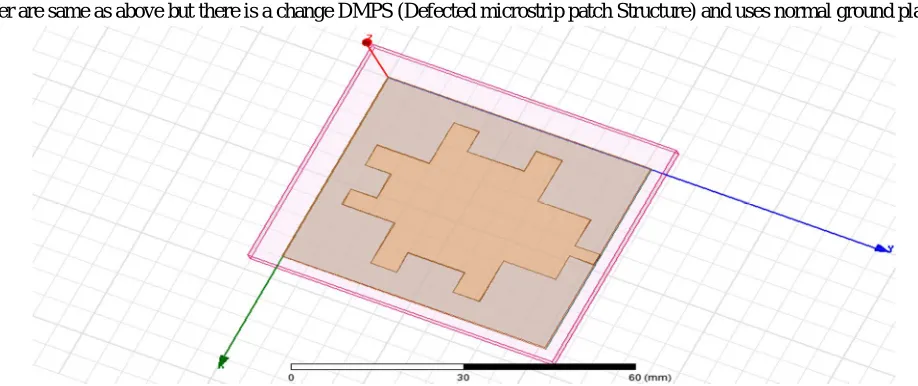
The geometry of proposed antenna which is microstrip line fed for IMT application is depicted in figure 3. In which the antenna parameter are same as above but there is a change DMPS (Defected microstrip patch Structure) and uses normal ground plane.
Figure 3:-Geometry dimension of proposed antenna with DMPS. Ground size 41.77x51.09mm
[image:3.612.74.533.528.721.2]A. The Return Loss Plot for the Designed Antenna at -10 DB Bandwidth With Microstrip Line Feed is Shown in Figure 4 as Below
Figure 4:-Simulated return loss
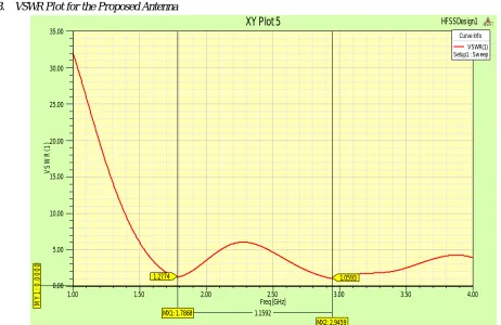
B. VSWR Plot for the Proposed Antenna
Figure 5:- VSWR plot
1.00 1.50 2.00 2.50 3.00 3.50 4.00
Freq [GHz] -35.00 -30.00 -25.00 -20.00 -15.00 -10.00 -5.00 0.00 d B (S (1 ,1 )) HFSSDesign1
XY Plot 1 ANSOFT
M Y 1 : -1 0 .0 0 0 0 MX1: 1.7868 MX2: 2.9459 -18.2865 -30.8203 1.1592 Curve Info dB(S(1,1)) Setup1 : Sw eep
1.00 1.50 2.00 2.50 3.00 3.50 4.00
Freq [GHz] 0.00 5.00 10.00 15.00 20.00 25.00 30.00 35.00 V S W R (1 ) HFSSDesign1
XY Plot 5 ANSOFT
[image:4.612.63.525.401.701.2]C. The Smith Chart and Radiation Pattern of Proposed Antenna
Figure 6:- Smith Chart and Radiation Pattern Plot.
Table 2:- Summarized results of the proposed antenna of dual band.
SR.NO Frequency (GHz)
RETURNLOSS (dB)
BANDWIDTH (GHz)
VSWR IMPEDANCE MATCHING 1 1.78 -18.28 1.88-1.69=0.19 1.27 58.65 2 2.94 -30.82 3.36-2.78=0.58 1.05 58.65
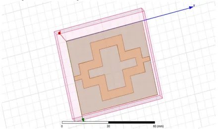
IV. DESIGN OF ULTRA WIDEBAND WITH DMPS AND DUAL FEEDING
The geometry of proposed antenna which is microstrip line fed for IMT application is depicted in figure 7. In which the antenna parameter are same as above but there is a change DMPS (Defected microstrip patch Structure) and uses normal ground plane. The dimensions of the designed antenna with microstrip line feed are same as
Figure 7:-Geometry dimension of proposed antenna for ultra wideband.
5.00 2.00 1.00 0.50 0.20 0.00 5.00 -5.00 2.00 -2.00 1.00 -1.00 0.50 -0.50 0.20 -0.20 0.00 0 10 20 30 40 50 60 70 80 90 100 110 120 130 140 150 160 170 180 -170 -160 -150 -140 -130 -120 -110
-100 -90 -80 -70 -60 -50 -40 -30 -20 -10 HFSSDesign1
Smith Chart 1 ANSOFT
[image:5.612.87.527.449.710.2]A. The Return Loss Plot for the Designed Antenna at -10 Db Bandwidth with Proximity Feed is Shown in Figure 8 As Below
Figure 8:-Simulated return loss
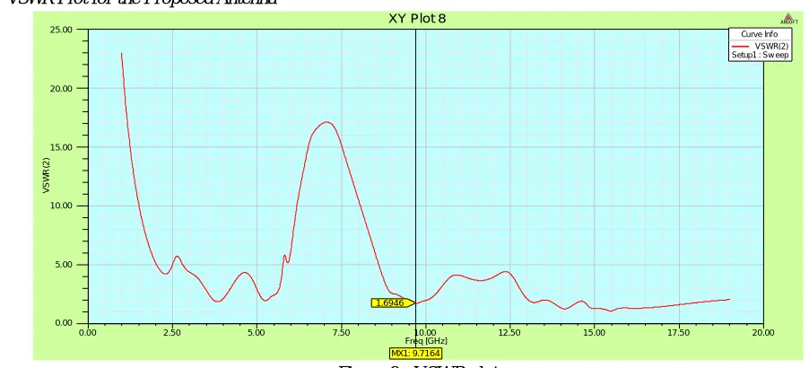
[image:6.612.54.537.120.537.2]B. VSWR Plot for the Proposed Antenna
Figure 9:- VSWR plot
Table 3:- Summarized results of the proposed antenna of ultra wide band.
Sr.No FREQUENCY
(GHz)
RETURNLOSS (dB)
BANDWIDTH (GHz)
VSWR IMPEDANCE
MATCHING
1 9.11 -26.81 14.5125-5.7470=8.7655 1.69 51.85
V. CONCLUSION
A Multiband (Dual band) and an ultra-wide band Microstrip patch antenna for wireless application has been designed and simulated using HFSS V13 software. A simulation will made in terms of bandwidth, return loss, VSWR and patch size and smith chart. it has been shown that microstrip antenna can be analyzed both theoretically and experimentally through simulations and fed by proximity feeding techniques. The multiband microstrip patch antenna can have multiple resonant frequency i.e. we can design a single microstrip patch antenna for multiple bands. Also, the feeding point selection i.e. proper matching of feed and patch is very important for having desirable features. The performance properties are analyzed for the optimized dimensions.
The proposed antenna has been designed by using rectangular type defected patch i.e DMPS (Defected microstrip patch Structure). We can also conclude that by changing the feed point where matching is perfect, the high return loss can be achieved at the resonant frequency.
0.00 2.50 5.00 7.50 10.00 12.50 15.00 17.50 20.00
Freq [GHz] -50.00 -40.00 -30.00 -20.00 -10.00 -0.00 10.00 d B (S (1 ,2 )) HFSSDesign1
XY Plot 3 ANSOFT
M Y 1 : -1 0 .0 0 0 0 MX1: 5.7470 MX2: 14.5125 -10.0019 -10.0059 8.7655 Curve Info dB(S(1,2)) Setup1 : Sw eep
0.00 2.50 5.00 7.50 10.00 12.50 15.00 17.50 20.00
Freq [GHz] 0.00 5.00 10.00 15.00 20.00 25.00 V S W R (2 )
XY Plot 8 ANSOFT
MX1: 9.7164 1.6946
[image:6.612.73.524.288.493.2]REFERENCES
[1] Ramesh Garg, PrakashBhartie, InderBahl, ApisakIttipiboon, “Microstrip Antenna DesignHandbook”, Artech House Inc. Norwood, MA, 2001, pp. 1-68, 253-316,.
[2] C.A. Balanis, “Antenna Theory (Analysis and Design)”, Second Edition, John Wiley & son Sons. [3] R. Garg, Microstrip Antenna Design Handbook,Artech House, 2001.
[4] Joseph Costan Tine1, Karim Y. Kabalan, Al EI-Hajj, MohammadRammal “New Multi-Band Microstrip Antenna Design For Wireless Communications” Vol. 49, No. 6,2007
[5] Abdel Fattah Sheta, Ashraf S. Mohra, And Samir F. Mahmoud “Modified Compact H-Shaped Microstrip Antenna For Tuning Multi-Band Operation”, 2008
[6] L. M. Si And X. Lv, “CPW-Fed Multi-Band Omni-Directional Planar Microstrip Antenna Using Composite Metamaterial Resonators For Wireless Communications” Pier 83, 133–146, 2008
[7] P.Mythili, Philip Cherian, S.Mridula, Binu Paul “Design Of A Compact Multiband Microstrip Antenna”, 2009 [8] PramendraTilanthe, P. C. Sharma “Design Of A Single Layer Multiband Microstrip Square Ring Antenna”, 2009
[9] Muhammad R. Khan, Mohamed M. Morsy, Muhammad Z. Khan and Frances J. Harackiewicz “Miniaturized Multiband Planar Antenna for GSM, UMTS, WLAN and Wimax Bands” 2011.
[10] Halappa R. Gajera, Anoop C.N, M. M. Naik. G, Archana S. P, Nandini R Pushpitha B.K, Ravi Kumar M.D, “The Microstrip Fed Rectangular Microstrip Patch Antenna(RMPA) with Defected Ground Plane for HIPERLAN/1” IJECT Vol. 2, Issue 3, Sept. 2011
[11] Zuhura Juma Ali, “A Miniaturized Ultra Wideband (UWB) Antenna Design for Wireless Communications” International Journal of Scientific & Research Publications, Vol 4, Issue 7, July 2014.
[12] A. Gnandeep reddy, k. Gopivasanth kumar, “Design And Simulation Of A L And U‐Shaped Slot Compact Planar Monopole Antenna”, International Journal of Science, Engineering and Technology, 2014.
[13] Udit Raithatha, S. Sreenath Kashyap & D. Shivakrishna, May 2015, “Swastika Shaped Microstrip Patch Antenna for ISM Band Applications” international journal IRJET.
[14] Sumeet Singh Bhatia, Jagtar Singh Sivian, Manpreet Kaur, “Comparison of feeding techniques for the design of microstrip rectangular patch antenna for x-band applications”, International Journal of Advanced Technology in Engineering and Science, Volume No.03, Special Issue No. 02, 2015.
[15] Gurpreet Kaur, Er. Sonia Goyal, “Effect of Height on Edge Tapered Rectangular Patch Antenna using Parasitic Stubs and Slots’’, International Journal of Engineering Trends and Technology (IJETT) – Volume 34 Number 8- April 2016.
[16] Ranjan Mishra, Raj Gaurav Mishra, Piyush Kuchhal, “Analytical Study on the Effect of Dimension and Position of Slot for the Designing of Ultra Wide Band (UWB) Microstrip Antenna” International Conference on Advances in Computing, Communications and Informatics (ICACCI) IEEE, Sept. 21-24, 2016, Jaipur, India.
[17] Udit Raithatha, S. Sreenath Kashyap & D. Shivakrishna, May 2015, “Swastika Shaped Microstrip Patch Antenna for ISM Band Applications” international journal IRJET.
[18] Sumeet Singh Bhatia, Jagtar Singh Sivian, Manpreet Kaur, “Comparison of feeding techniques for the design of microstrip rectangular patch antenna for x-band applications”, International Journal of Advanced Technology in Engineering and Science, Volume No.03, Special Issue No. 02, 2015.
[19] Gurpreet Kaur, Er. Sonia Goyal, “Effect of Height on Edge Tapered Rectangular Patch Antenna using Parasitic Stubs and Slots’’, International Journal of Engineering Trends and Technology (IJETT) – Volume 34 Number 8- April 2016.
[20] R.K. Sharan, S.K. Sharma, “ A .Gupta, R.K Chaudhary, An Edge Tapered Rectangular Patch Antenna with Parasitic Stubs and Slot for Wideband Applications, Wireless Pers Commun Vol 86, pp 1213–1220, 2016.
[21] M. Tarikul Islam, M. Samsuzzaman, M. Z. Mahmud, M.T. Islam, “A Compact Spectacles Shaped Patch Antenna for UWB Applications”, 9th International Conference on Electrical and Computer Engineering, IEEE, 20-22 December, 2016, Dhaka, Bangladesh.