Technology (IJRASET)
Cipher key Block Cipher Encryption Plain text Cipher text Cipher key Block Cipher Encryption Cipher text Plain textMulti Core Processor Arrays Cores
Optimization in AES Engines
Chandrahas Reddy.M
Abstract— In the present scenario protecting the sensitive information is done by several encryption standards. AES encryption is modern technique which is based on the principle of substitution-permutation network. Advanced encryption standard is well known as the symmetric key standard for encryption and decryption of blocks of data.
In encryption, the AES accepts a plaintext input, which is limited to 128 bits, and a key that can be specified to be 128 bits to generate the Cipher text. Software implementation of AES is now extended to hardware also. Due to this hardware implementation, there is a tremendous improvement in the throughput & energy efficiency. By exploring different granularities of AES as a One round encryption, Nine loop Encryption, Parallel Mixed Column and Full Parallelism and mapping these implementations on a field programmable gate array system. In comparison with published AES cipher implementations on general purpose processors the proposed design has occupied less area and small delay.. AES analysis is performed on all levels of abstraction (verilog). The motivation behind the work is to optimize area, faster processing. AES algorithm is simulated at different levels in CADENCE to ensure that the design optimizes power, area and delay.
Index Terms— One round encryption, Nine loop Encryption, Advanced encryption standard (AES), Field Programmable Gate Array (FPGA).
I. INTRODUCTION
Highlight The National Institute of Standards and Technology, (NIST), solicited proposals for the Advanced Encryption Standard, (AES). The AES is a Federal Information Processing Standard, (FIPS), which is a cryptographic algorithm that is used to protect electronic data[5]. The AES algorithm is a symmetric block cipher that can encrypt, (encipher), and decrypt, (decipher), information. Encryption converts data to an incomprehensible form called cipher-text. Decryption of the cipher-text converts the data back into its original form, which is called plaintext. The AES algorithm is capable of using cryptographic keys of 128, 192, and 256 bits to encrypt and decrypt data in blocks of bits.
To provide data security cryptography plays a significant role. It obstructs unauthorized persons to read secured data by facilitating us to store sensitive information or transmit it across insecure networks. Large quantities of different encryption algorithms are came in to existence by the importance of secure ex-change of digital data, which can be classified into two groups: asymmetric encryption algorithms (with public key algorithms) and symmetric encryption algorithms (with private key algorithms). Asymmetric key algorithms are very slow compared to Symmetric key algorithms. The algorithm consists mainly three parts: Cipher, Inverse Cipher and Key Expansion. Cipher transforms data to an incomprehensible form called cipher text while Inverse Cipher transforms data back into its original form called plaintext[2]. Key is generated by process key Expansion and Key Schedule that is used in Cipher and Inverse Cipher procedure. Cipher and Inverse Cipher are generated by specific number of rounds. For the AES algorithm, during the execution of the algorithm the number of rounds to be performed is dependent on the key length..
AES is an encryption algorithm, which performs several rounds of transformations on a 128 bit data block of input using a secret key called cipher key, which generates cipher text of 128 bits as output. The 128 bits are divided as 4*4 array block called State; each block consists of a byte.[1].
(b)
(a)
Technology (IJRASET)
©IJRASET 2013: All Rights are Reserved
137
The number of loops (10, 12, 14) repeated in the algorithm depends on the length of round key, which can be of 128,192,256. Mainly four transformations play significant role in encryption process: Sub Bytes, Shift Rows, Mix- columns, Add Round key.
[image:3.612.184.416.159.410.2]Decryption is similar: which takes, in this example, a 128-bit block of encrypted cipher text together with the secret key, and yields the original 128-bit block of plaintext. The messages which are longer then the block size are encrypted by a mode of operation. The stream ciphers are used to contrast Block ciphers, which operates on individual digits one at a time and the transformation varies during the encryption.[1].
Fig. 2.Block diagram of AES encryption
A. Sub-Bytes
The transformation of SubBytes is a nonlinear byte substitution, where each of the state bytes independently operated. According to the substitution Box, each byte from the input is replaced by another byte taken from the S-Box. The S-Box used is derived from the multiplicative inverse over GF(28), known to have good
Fig. 3.Substitute Bytes Stage of the AES algorithm.
non-linearity properties. To obstruct attacks based on simple algebraic properties, the S-Box is assembled by joining the inverse function with an invertible affine transformation[2].
B. Shift-Rows
[image:3.612.166.389.520.637.2]Technology (IJRASET)
Fig. 4.Shift Rows Stage
offset. For AES first row is left unchanged. Each byte of the second row is shifted one to the left. Similarly the third and the fourth rows are shifted by offsets of two and three, i.e The bytes in the second, third, and forth rows are cyclically shifted by one, two, and three bytes to the left, respectively.
C.Mix-Columns
[image:4.612.147.565.279.436.2]During this process, only a matrix multiplication needs to be executed. Each column of the state array is considered as a polynomial over GF(28) and multiplied with a fixed polynomial taken as a matrix produces transformed cipher.
Fig. 5.Mix-Column Stage
D.Add round Key
This operation is simple. The corresponding byte of input data and the expanded key are XORed i.e. around key is added to the state array using a bitwise exclusive-or (XOR) operation. Round keys are calculated in the key expansion process.
II. SUB-BYTES
Sub-byte transformation is nothing but byte by byte substitution from the S-box table. The table consists of 16*16 matrix of byte, consists of all possible combinations of an 8 bit sequence (16*16 = 28 = 256). Each byte from the state is mapped into a new byte as follows: the left most nibble of a byte from the state represents row of the s-box and the rightmost nibble represents a column[2].
[image:4.612.174.415.579.701.2]Technology (IJRASET)
©IJRASET 2013: All Rights are Reserved
139
ROM based lookup table is the most general implementation of the S-Box which is used to store pre-computed values. ROM is filled with all 256 values and the input byte would be wired to the ROM’s address bus. This method experiences from an unavoidable delay, because read and write operation of ROMs requires a fixed access time.
The S-box is generated by calculating the multiplicative inverse in GF(28) followed by affine transformations. In The reverse process, inverse affine transformation is applied followed by multiplicative inverse.
SubByte: -> Multiplicative Inversion in GF(28) -> Affine Transformation
InvSubByte: -> Inverse Affine Transformation -> Multiplicative Inversion in GF(28).
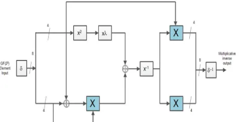
Using composite field arithmetic the multiplicative inverse module for s-box is constructed. Both subbytes and inverse subbytes are using multiplicative inverse so in this paper, the design of multiplicative inverse module is concentrated.
the multiplicative inverse can be calculated using the equation
(bx + c)-1 = b(b2B+bcA+c2)-1x + (c + bA) (b2B+bcA+c2)-1 (2.1)
bx+c = b->most significant nibble, c-> least significant nibble. (bx + c)-1 = b(b2ƛ+ c (b+c))-1x + (c + bA) (b2ƛ + c (b+c))-1 (2.2)
From the above equation it is clear that multiply, addition, squaring and multiplication inversion in GF(24) operations in Galois Field. The circuit for calculating the multiplicative inverse can be constructed by transforming the each operator as a individual block.
III. KEYSCHEDULING
In the AES algorithm, each round requires encryption key which has to be derived from the original 128-bit encryption key. One of the four steps of each round, for both encryption and decryption, involves XORing of the round key with the state array[3].
To produce a key schedule, the AES algorithm requires the Cipher Key, K, which performs a Key Expansion routine. By this key expansion process Nb*(Nr + 1) words are generated. An initial set of Nb words are required, and each of the Nr rounds needs Nb words of key data. Finally a linear array of 4-byte words are produced through key schedule process, denoted [wi ], with i in the range 0 £ i < Nb(Nr + 1).
The new word w[i] depends on the immediately preceding word, w[i − 1], and the word four positions back w[i − 4].
A. Rot Word is the operation performed circular left shift of one-byte on a word. This means that an input word
[b0,b1,b2,b3] is transformed into [b1,b2,b3,b0].
B. Sub Word is a nonlinear byte substitution performed on each byte of its input word, using the s-box discussed earlier.
Technology (IJRASET)
Fig.7.Rcon for 10 rounds
IV. ONEROUNDENCRYPTION
The most significant parts of AES algorithm are SubBytes, ShiftROws, Mixcolumn, Addround key. In this paper we present one round of encryption which requires at least eight cores for processing as shown in figure. It performs one round of transformations on a 128 bit data block of input using a secret key called cipher key, which generates cipher text of 128 bits as output, in parallel the cipher key is generated through process called key schedule. This one round encryption is simulated in CADENCE and results are provided in terms of performance metrics area and power.
Fig.8. One Round Encryption
V. NINE LOOP ENCRYPTION
Fig.9. Nine Loop Encryption
Technology (IJRASET)
©IJRASET 2013: All Rights are Reserved
141
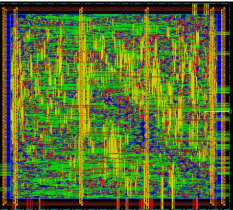
(OTOP). In parallel with the main algorithm the key expansion is processed, the throughput of the OTOP implementation is decided by the nine (Nr − 1 = 9) loops in the algorithm. It performs nine rounds of transformations on a 128 bit data block of input using a secret key called cipher key, which generates cipher text of 128 bits as output. Every round requires cipher key for encryption, which is generated through key scheduling process. This Nine round encryption is simulated in CADENCE and results are provided in terms of performance metrics area and power. Comparing to one round encryption it obtains much power and area, which were optimized
Fig.11.Layout of Nine Loop Encryption in Cadence
VI. FULL PARALLELISM
This is a novel method of AES implementation amalgamates the Parallel blocks of SubBytes & MixColumns. Mapping of these blocks of Full Parellism are shown in figure. The advantage of this model is throughput, comparing to other methods, it processes in parallel by segregating 16 bytes of SubyYtes and MixColumns into 4 bytes. It performs nine rounds of transformations on a 128 bit data block of input using a secret key called cipher key, which generates cipher text of 128 bits as output . the cipher key is produced parallel through key scheduling process[1]. The encrypting process is similar to nine round encryption model, but differs in segregation of a 128 bit to 32 bit and processing these in parallel through transformations of sub-bytes and mix columns. Parallelizing the SubBytes process with more than four processors would only increase the area and power overhead with performance improvement of speed.
Technology (IJRASET)
Fig.13.RTL Schematic of Full Parallel Encryption
Fig.14.Layout of Full Parallel Encryption in Cadence
VII. EXPERIMENTALRESULTS
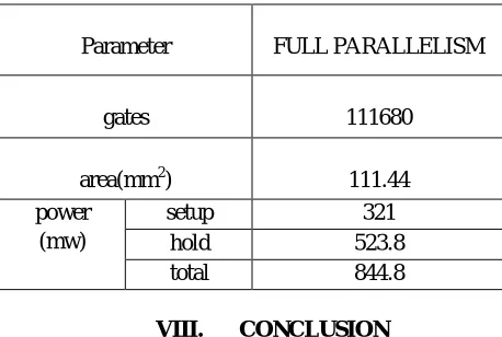
In this section the gate level results of Nine Loop Encryption and Full Parallelism are implemented with the Cadence synthesize tool. Table I presents the results of the area, number of gates used, calculating total power with respect to setup and hold power for Nine Loop encryption. Table II presents the results of the area, number of gates used, calculating total power with respect to setup and hold power for Full Parallelism encryption. From the results it is shown that Full Parallelism requires less area and less power compared to Nine Loop encryption.
Table I: Gate-level results for Nine Loop Encryption Parameter NINE LOOP
ENCRYPTION gates 114267 area(mm2) 114.02 power
(mw)
[image:8.612.180.418.284.499.2]Technology (IJRASET)
©IJRASET 2013: All Rights are Reserved
[image:9.612.191.420.88.242.2]143
Table II: Gate-level results for Full Parallelism
Parameter FULL PARALLELISM
gates 111680
area(mm2) 111.44 power
(mw)
setup 321 hold 523.8 total 844.8
VIII. CONCLUSION
The Advanced Encryption Standard algorithm is an iterative private key symmetric block cipher that can process data blocks of 128 bits through the use of cipher keys with lengths of 128, 192, and 256 bits. An efficient FPGA implementation of 128 bit block and 128 bit key AES cryptosystem has been presented in this paper. Optimized and Synthesizable Verilog code is developed for the implementation of 128 bit data encryption process & description is verified using CADENCE. All the transformations of algorithm are simulated using an iterative design approach in order to minimize the hardware consumption. Performance metrics like area and power are tabled for models like Nine Loop Encryption and Full parallelism.
REFERENCES
[1] Bin Liu and Bevan M. Baa, “Parallel AES Encryption Engines for Many-Core Processor Arrays,” IEEE TRANSACTIONS ON COMPUTERS, VOL. 62, NO. 3, MARCH 2013.
[2] Edwin NC Mui, “Practical Implementation of Rijndael S-Box Using Combinational Logic”.
[3] N.Ahmad and S.M.Rezaul Hasan, “Efficient integrated AES crypto-processor architecture for 8-bit stram cipher,” ELECTRONICS LETTERS 8th November 2012 Vol. 48 No. 23
[4] Mehran Mozaffari Kermani,“Fault Detection Schemes for High Performance VLSI Implementations of the Advanced Encryption Standard”. [5] NIST, “Advanced Encryption Standard (AES),” http://csrc.nist.-gov/publications/fips/fips197/fips-197.pdf, Nov. 2001.
[6] NIST, “Data Encryption Standard (DES),” http://csrc.nist.gov/ publications/fips/fips46-3/fips46-3.pdf, Oct. 1999
[7] D. Mukhopadhyay and D. RoyChowdhury, “An Efficient end to End Design of Rijndael Cryptosystem in 0:18_m CMOS,” Proc. 18th Int’l Conf. VLSI Design, pp. 405-410, Jan. 2005.
[8] J. Daemen and V. Rijmen, The Design of Rijndael. Springer-Verlag, 2002.
[9] S. Gueron, “Intel Advanced Encryption Standard (AES) Instruc-tions Set,” Jan. 2010.