DEPTH ESTIMATION FROM 3D RECONSTRUCTED SCENE USING STEREO VISION
OMER MOHAMED OMER BA-SALEEM
A project report submitted in partial fulfillment of the requirement for the award of the
Degree of Master of Electrical Engineering
Faculty of Electrical and Electronic Engineering Universiti Tun Hussein Onn Malaysia
iv
CONTENTS
CONTENTS ... iii
LIST OF TABLES ... vi
LIST OF FIGURES ... vii
LIST OF APPENDICES ... ix
ABSTRACT ... x
CHAPTER 1 ... 1
INTRODUCTION ... 1
1.1 Project background ... 1
1.2 Problem statement and Motivation ... 2
1.3 Objectives of the Project ... 3
1.4 Project Scope ... 3
1.5 Thesis outline ... 4
CHAPTER 2 ... 5
LITERATURE REVIEW ... 5
2.1 Introduction ... 5
2.2 Related works ... 5
2.3 Stereo Vision ... 15
2.3.1 Stereo matching... 17
2.3.2 3D reconstruction ... 17
2.4 Summary ... 18
CHAPTER 3 ... 19
METHODOLOGY ... 19
3.1 Introduction ... 19
3.2 Stereo vision flowchart ... 19
3.4 Hardware setup... 22
3.5 Camera Calibration ... 23
3.6 Image Pre-Image processing ... 24
3.7 Stereo image rectification ... 25
3.8 Stereo matching ... 26
3.9 Dynamic programming... 28
3.10 3D map reconstruction ... 29
3.11 Graphical user Interface ... 30
CHAPTER 4 ... 31
RESULTS AND DISCUSSION... 31
4.1 Introduction ... 31
4.2 Accuracy of the camera at indoor environment ... 32
4.2.1 indoor stereo camera accuracy at 1 meter ... 32
4.2.2 Indoor stereo camera accuracy at 1.5 meters ... 34
4.3 Accuracy of the camera at indoor environment ... 36
4.3.1 Outdoor stereo camera accuracy at 1 meter ... 36
4.3.2 Outdoor stereo camera accuracy at 1.5 meters ... 38
4.4 Summary ... 40
4.5 Graphical user interface ... 41
CHAPTER 5 ... 42
CONCLUSION AND RECOMMENDATION ... 42
5.1 Conclusion ... 42
5.2 Recommendation ... 43
REFERENCES ... 44
vi
LIST OF TABLES
TABLE TITLE PAGE
2.1 Data comparison of stereo vision system 6
2.2 3D mapping techniques comparison 18
LIST OF FIGURES
FIGURE NO TITLE PAGE
1.1 Stereo Vision Camera 2
1.2 Rescue Robots based on vision 3
2.1 The actual object and the 3D virtual model 6
2.2 3D point cloud 7
2.3 The picture of the object taken with two cameras 8
2.4 Kinect camera 9
2.5 2.6 2.7
Corresponding matched features between the two images 3D map using Kinect sensor at indoor environment SwissRanger3000 and high-resolution CMOS-camera
9 11 13
2.8 Time of flight (TOF) camera principle 13
2.9 Depth estimation using geometry approach 15
2.10 Stereo cameras layout 15
2.11 Corresponding matched features between the two images 17
3.1 Stereo Vision System Flow Chart 20
3.2 stereo triangulation and geometry 21
3.3 Hardware setup for stereo camera 22
3.4 Chessboard pattern for camera calibration 23
3.5 stereo camera calibration 23
3.6 Image acquisition from both stereo cameras 24 3.7 Gray scale for right and left stereo images 24
3.8 Stereo image rectification 25
3.9 Anaglyph effect 25
3.10 Block matching method searching on the scanline 27
3.11 Depth map from basic block matching 27
viii
3.13 Graphical user Interface 30
4.1 Right stereo Image 32
4.2 Left stereo Image 32
4.3 3D model at indoor environment when depth is 1 meter 32 4.4 3D model at indoor environment when depth is 1.5 meter 34
4.5 Right stereo Image 36
4.6 Left stereo Image 36
4.7 3D model at outdoor environment when depth is 1 meter 36 4.8 3D model at outdoor environment when depth is 1.5 meter 38
LIST OF APPENDICES
APPENDIX TITLE PAGE
x
ABSTRACT
CHAPTER 1
INTRODUCTION
1.1 Project background
Many robot’s applications need navigation to let the robot get an accurate information of the robot position with prospective of its surrounding environment. Autonomous robots using sensors to locate their position to avoid colliding with obstacles.
Many sensors that are uses for mobile robot navigation such as ultrasonic sensor which consider as cheap sensor and have a low accuracy, Laser range finder can provide high accuracy in measurement but it has an expensive cost. In addition, visionary sensors are more suitable such as stereo vision, Kinect RGB-D camera and time of flight camera, because it acquires the exact information of the environment comparing to other kind. It extracts features from the captured images and represents them in terms of plane location and depth in relation to the current robot position[1].
2
Figure 1.1 Stereo Camera
For the full 3D reconstructed model, the map models the environment without any assumptions about it. The representation models the occupied areas as well as free path. In the case of unknown areas, the navigation information about the areas is important for the autonomous exploration and for future navigation.
1.2 Problem statement and Motivation
environment which can help to give an information’s of the nature of that environment. Despite vision-based system can only function under a very specified and controlled environment. The changing of the background and illumination are serious difficulty since the testing of depth using stereo vision that proposed in this thesis will conducted at indoor and outdoor environment.
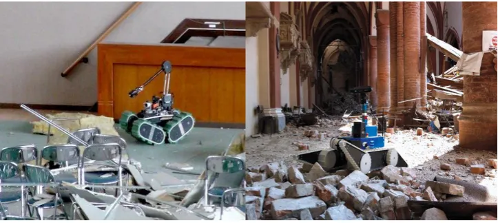
Figure 1.2: Rescue Robots based on vision
1.3 Objectives of the Project
1. To develop a stereo vision system to estimate depth from 3D reconstructed scene. 2. To develop a graphical user interface (GUI) to monitor the performance of the
stereo vision system.
3. To analyse the performance of the proposed stereo vision system.
1.4 Project Scope
1. MATLAB will be used to develop low-cost stereo vision system in order to estimate depth.
2. The experimental environment in this project will be at indoor and outdoor environment and it will estimate the depth from the reconstructed 3D model using MATLAB. However, the stereo vision function under a specified condition such as: static environment with consistent background and light intensity.
4
1.5 Thesis outline
CHAPTER 2
LITERATURE REVIEW
2.1 Introduction
This chapter reviews the past works related to depth estimation by reconstructed a scene by 3D mapping and describes all the techniques used previously. A comprehensive comparison between these techniques is done between different methods to help deciding what method to be followed on this project. It also explains further in more details on the selected stereo vision based system covering all the important theories.
2.2 Related works
Recently a lot of research’s have been conducted to build a 3D map for the surrounding
6
[image:15.595.158.489.133.272.2]Figure 2.1 below shows the box that simulated using C++ and Open GL graphic library to obtain a 3D virtual model of the actual box.
[image:15.595.153.485.347.542.2]Figure 2.1: The actual object and the 3D virtual model [1].
Table 2.1: Data comparison of stereo vision system [1].
Item Real (cm) Model (cm)
a (-4.9, 0, 33) (-5.0, 0, 33)
B (4.9, 0, 33) (4.8, 0, 32)
C (-4.9, 4.5, 33) (-5.0, 4.7, 33) D (4.9, 4.5, 33) (4.8, 4.8, 32)
E (-9.8, 0 ,42.8) (-10.2, 1.1, 41.5)
F (9.8, 0, 42.8) (11.1, 0.5, 44.0)
G (-9.8, 9.8, 42.8) (-10.2, 11.3, 41.5)
H (-9.8, 9.8, 42.8) (11.1, 11.6, 43.8)
As shown from table 2.1 this experiment has been done at indoor environment
for a box shape. However, some coordinates errors after doing the 3D modelling, however most points were well detected and their coordinates are nearly the same with their real coordinates. The biggest difference is less than 2cm.
outdoor environment by taken a picture of the chessboard camera from the right and left camera around 14 chessboard images have been taken.
[image:16.595.210.427.318.504.2]The disparity map has been created from a pair of the stereo vision cameras. To get estimate disparity a semi-global block matching method have been used this matching is by forcing the similarity disparity on neighbouring blocks. The additional constraint method shows a prefect and more accurate disparity estimate than in basic block matching. The semi global matching algorithm is slight difference a global cost function for penalizing the small disparity steps that are often part of slanted surface, less than real discontinuities. This paper used a point cloud to generate a coordinates of the 3D virtual reconstructed scene. Moreover, from the information that got from the point cloud the interest object will be segmented out[6].
Figure 2.2: 3D point cloud[6].
The experimental have been done by measuring the distance between the real distance and measured distance from 3D map by the stereo vison camera. The measuring distance have been done by set the real distance from 50 to 190 cm. In addition, the mean accuracy of the stereo camera reach to 89.95% at outdoor. unfortunately, the researcher did not check about the results at indoor environment.
8
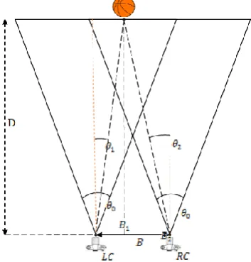
[image:17.595.239.416.139.324.2]pixel to improve the computational images. The baseline between two cameras was 15 cm. which started by taken the right and left image of the scene respectively[7].
Figure 2.3: The picture of the object taken with two cameras.
The distance D measures by using the following equation:
𝐷 = 𝐵
2𝑡𝑎𝑛(𝜃0
2)(𝑥1−𝑥2)
(2.1)
The experiment has been done at outdoor environment Furthermore, the method achieved high accuracy reach to 20 meters. The percentage error reach to 2.13% which give mean accuracy reach to 99.87%.
Stereo vision approach must carry out some sort of details extraction instead
of the 2D maps which is often represented in a condensed 2D grid module with no realistic or scalable 3D generalization. For instance, stereo data was used to find the 3D planes Hough transform in the surrounding and then extracted through a voting scheme. Although some manual guidance is used when there is a lack of input data, a stereo vision is fused with information to recover 3D features. On the other hand, 3D landmarks in the captured image are used to construct the map. Such a construction depends on predicting the ego-motion of the robot, tracking the landmarks using the odometer for estimation, and superposing the landmarks to find the map[8].
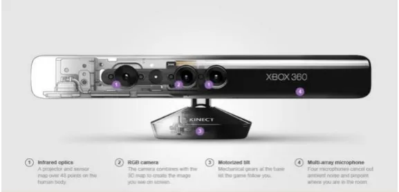
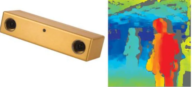
Microsoft has been discussed and analysis of the accuracy and resolution of its depth map has been provided. Furthermore, experimental results presented a theoretical error of the depth measurement from the disparity which shows a random error of depth measurement increases with increasing distance to the sensor[9].
Figure 2.4: Kinect camera
[image:18.595.155.499.551.674.2]The kinect sensor consist of an infrared laser emitter and an RGB camera as shown in figure 2.3. The laser source emits a signal beam which split into multiple beams creating a constant pattern of the speckles projected onto the scene. The captured patterns by the infrared camera correlated against the refence while the refence patters is obtained by capturing a plan at known distance from the sensor and store in it. when speckle is projected the infrared image will be shifted in the direction of the baseline between the laser projector and the prospective sensor of infrared camera. These shifts will measure the disparity map. For each pixel to the distance can then be retrieved from the corresponding disparity[9].
10
The depth information from Kinect sensor is very noisy in long range. Kourosh Khoshelham and Sander Elberink have investigated the noise characteristics of the Kinect sensor and authors conclude that for mapping applications the data should be acquired within 1–3 m distance to the sensor. At larger distances, the quality of the data is degraded by the noise and low resolution of the depth measurements
The random error of the depth measurements shows increases quadratically with increasing in distance from the sensor while at the same time the depth resolution also decreases quadratically with increasing the distance. This effect was in the maximum range that has been tested which is 7 cm for 5 meters. However, at 1 meter point spacing in the depth direction quite small about 2 mm, at 3 m and 5 m the points are clearly distribute in several layers intervals corresponding to the depth resolution which is about 2.5 cm for the plan at 3 m distance[9].
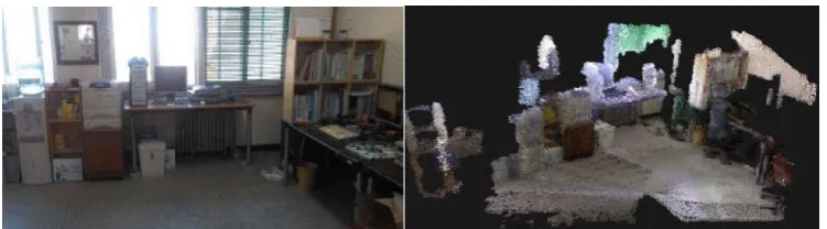
Kinect camera has been used to build a 3D map for a mobile robot at indoor
environment. The 3D model can get by extracting the SURF from the input colour image as a first stage and match the current frame with previous captured frame. Then the matched features are transformed to 3D coordinate points data using depth information. The 3D points data sets of two consequent image are combined to estimate camera pose and then the 3D will have built. Furthermore, the iterative closest point (ICP) algorithm is employed to minimize the algorithm between the two-point cloud[10]. The main applications are to register geometric 3D, and to estimate a relative pose for the localization and the map in the first step the algorithm selects the closest point by:
𝑝̂ = arg 𝑚𝑖𝑛𝑝∈𝑝𝑗‖𝑝𝑗− 𝑞𝑖‖ (2.2)
Where 𝑝 = {𝑝1, … , 𝑝𝑛} is a set of the previous frame 3D coordinated features
𝑄 = {𝑞1, … , 𝑞𝑛} is set of the current frame 3D coordinates features, and 𝑝̂ is the closest
point of the point 𝑞𝑖, In the second step the transformation pose error is estimated by minimization error.
𝐸(𝑅, 𝑡) = ∑𝑞𝑗∈𝑄‖𝑝̂ − (𝑅𝑞𝑖+ 𝑡)‖ (2.3)
those of the previous frame. The estimated transformation error is aligned to that of the previous frame. In addition, the trajectory of the camera is a set of pose information obtained by the ICP algorithm. Whole 3D point cloud map is reconstructed by accumulating the point cloud map of depth image at each frame of camera trajectory,
Figure 2.6: 3D map using Kinect sensor at indoor environment.
the evaluation of the accuracy that collected from the 3D map data is done by
comparing the estimated length distance of the given object in 3D map with the real distance of the object. Moreover, the experiment has been done at indoor environment. the error calculated shown an error rate less than 2%.
RGB-D cameras to refer to the emerging class of consumer depth cameras that provide both colour and dense depth values at high resolution and real-time frame rates. To reliably measure depth, RGB-D cameras use active sensing techniques, based on projected texture stereo, structured light, or time of flight. Moreover, RGB-D cameras, such as Kinect from Microsoft, are active sensors that provide high-resolution dense colour and depth information at real-time frame rates. The wide availability of affordable RGB-D cameras is causing a revolution in perception and changing the landscape of robotics and related fields. One of the RGB-D cameras applications 3D mapping which is suited for the purpose. The operation starts by capture a scene in 3D point clouds without the loss of 3D information that occurs in (optical) cameras. The reality It is there is no surprise that 3D virtual mapping and modelling is one of the first areas in which RGB-Depth cameras have been successfully implemented. The point of using RGB-D sensors for mapping is to
12
accurate in both geometry (shape) and appearance (colour). The flow diagram in the figure shows their approach, in which a combination of image-based and shape-based matching techniques are used to align RGB-D frames. As in 2D mapping, there are two issues to address for frame alignment: 1) visual odometry: how to align two consecutive RGB-D frames, and 2) loop closure: how to detect loop closures and adjust camera poses so that they are globally consistent[11].
In many automatization areas like robotics or automotive engineering, the determination of distance information as well as the reconstruction of objects or complete environments is a fundamental task with respect to computer vision. During the last years, a compact and low-priced alternative to common 3D scanning devices like laser scanners, structured light scanners or stereo-vision setups has gained in popularity. A time-of-flight camera (ToF camera) is a range imaging camera system that resolves distance based on the known speed of light, measuring the time-of-flight of a light signal between the camera and the subject for each point of the image. The
TOF camera works like a lidar with the advantage that the sense is captured at the same time and that there are no moving parts. ToF (Time of Flight) 3D Range Camera is composed of the illuminator and receiver. The illuminator modulates light source in a pulse-shape and sends it out to the object. The receiver’s detector, whose modulation interval is synchronized with the light source, detects the bounced-off light and measures the phase difference. Object’s distance is calculated by analysing measured
Figure 2.7: SwissRanger3000 and high-resolution CMOS-camera[12]
The distance d to the according object region is finally given by:
d =
𝑐2
×
∆Φ
2πf
(2.4)
where:
d = the depth or the distance between the camera and the object.
c = 3×10⁸ m/s represents the speed of light.
∆Φ = pixel’s phase shift between 0 and 2
π
.
f = is the signal’s modulation frequency (commonly 20 MHz are used, resulting in an
unambiguous distance range of 7.5 m).
[image:22.595.167.484.496.668.2]14
2.3 Stereo Vision
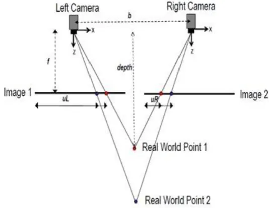
[image:24.595.194.462.198.405.2]The vision system is a technique aimed at inferring depth from the sense that captured by stereo two cameras. The system provides a 3D structural information for the surrounding environment. The depth of an object from the camera pose is illustrated by Figure 2.9 and 2.10.
Figure 2.9: Depth estimation using geometry approach.
[image:24.595.185.455.474.658.2]16
It is possible to recover depth from two images. Meanwhile, the 2D capture images by on the plan of projection resent the view of scene from camera view. The disparity or the 3D features are providing the depth information’s which will send to
the robot to enable navigate the robot indecently avoiding it from colliding with obstacles.
Figure 2.9 shows an example coordinates of the object point conversion from the 2D image coordinate to the 3D camera coordinate. Stereo vision system and the two cameras whose X axes are overlap each other and y axes are parallel to each other.
𝑈𝑅and 𝑈𝐿 are image planes have the same y value after rectification. The difference
between image planes in x axis is disparity d. The 3D position (in the camera coordinate frame) of feature with disparity d is given by[3]:
𝑍 =𝑓𝐵
𝑑 (2.5)
Where:
Z= The depth or the real point.
B= The baseline of the stereo camera.
f = the focal length.
d= the disparity between the right and left images.
The depth information obtained from the disparity that got by using the stereo
2.3.1 Stereo matching
The 3-D information can be obtained from a pair of images, also known as a stereo pair, by estimating the relative depth of points in the scene. The scene structure is segmented by a set of planar disparity planes[16], which is constructed by matching corresponding points in the stereo pair. The scene structure is modelled by a set of planner disparity plans. Three parameters can obtain the Disparity planes which are C1, C2 and C3 that define the disparity d for each image pixel (𝑥, 𝑦): 𝑑 = 𝐶1𝑥 + 𝐶2𝑦 + 𝐶3. However, due to the variety number of disparity planes the number is
reduced by extracting a set of disparity planes that is enough to represent the scene structure. The most popular dissimilarity measures are squared intensity differences
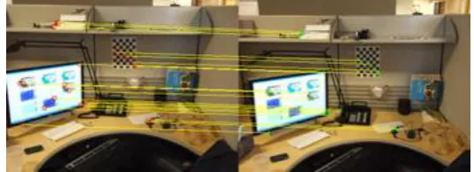
[image:26.595.193.461.403.500.2](SD) and absolute Intensity differences (AD) which are directly assuming the constant colour constraint[17]. The yellow lines indicate the corresponding matched features between the two images in Figure 2.11.
Figure 2.11: Corresponding matched features between the two images.
2.3.2 3D reconstruction
18
constant standard deviation of the disparity map. However; it is always assumed a varying disparity standard deviation interrelated with the estimated disparity. Faraway objects have a smaller standard deviation since the disparity is smaller than the disparity of the close objects and vice versa.
2.4 Summary
To sum up, there are main methods have been demonstrated for building 3D maps of the surrounding. First method is by using the Stereo camera which consist of pair of cameras and which make this method popular is easy to implement and the commercial cost unlike the second method Kinect camera which contain a single RGB camera and a depth finder sensor which its cost is also affordable a little bit expensive than the
stereo camera but it can provide an online 3D mapping and clear depth mapping but also its sensitive to external infrared source such sun light which make it more used
[image:27.595.120.522.590.762.2]for indoor environment, However, in our project that we need to use the system to estimate the depth in indoor and outdoor environment. Finally, our third technique is by using time of flight camera (TOF) have promising results at industrial future in building 3D mapping but it still expensive for research approaches comparing to other vision cameras. TOF camera can provide real time 3D mapping with high resolution depth mapping but have a noise at the long range. In this project stereo vision camera will be implemented regarding to its affordable requirements. The following table gives a summarize on the three techniques. Table 2.2 presents some of the differences and similarities phases among the three different techniques.
Table 2.2: 3D mapping techniques comparison Criteria
Method
Strength Weakness Cost
Stereo camera Popular
Easy to implement
passive 3D depth estimation
Affordable
Camera +depth sensor (Kinect)
Online 3D mapping Sensitive to external infrared source (sunlight)
Affordable
Time of Flight camera (TOF)
Real time 3D mapping high resolution depth map
CHAPTER 3
METHODOLOGY
3.1 Introduction
This chapter first explains the overall flow of tasks in this project. Then it describes in full details the procedures taken to reach the results represented by a 3D representation of the surrounding. It explains how to reconstruct the 3D model of an object from a pair of stereo images to get the depth. The flowchart of stereo-based vision system is shown in Figure 3.1, where the process starts by capturing two images and performing the pre-processing to those images. The stereo matching process which calculates for the disparity is the essential process to find the depth information.
3.2 Stereo vision flowchart
Figure 3.1 shows the flowchart of the stereo vision which start by capturing both right and left pictures of the object. In the pre-image processing stage colour of both pictures converts from RGB to gray scale. In addition, median filter is added as part of
20
Figure 3.1: Stereo Vision System Flow Chart. start
Capture stereo images
Images pre-processing: - convert from RGB to gray scale
Stereo rectification
Stereo matching
Disparity map
3D reconstruction
3.3 Depth recovering
The principle point has been calibrated to have the same pixel coordinates in their respective left and right image. The images are row-aligned and that every pixel row of one camera aligns exactly with the corresponding row in the camera aligns exactly with corresponding row in the other camera.
It is possible to recover a depth from two images taken by stereo camera as shown in Figure 3.2 where point 𝑾is the point of an object in front of stereo camera in the real world. While 𝑷 and 𝑷′ represent the Left and the right position of the
cameras respectively and 𝑿𝑹 and 𝑿𝑳 represents the images plan of the objective from the left and right camera respectively. Then the image in the left camera will form in 𝑶𝑹and the image in the left camera will form in𝑶𝑻.
𝑋𝑅 = 𝑓𝑥𝑅
𝑍𝑅 (3.1)
𝑋𝐿 = 𝑓 𝑥𝐿
𝑍𝐿 (3.2)
[image:30.595.218.418.471.672.2]Where 𝒇 represents the focal length, which is the distance between image plan and the center of the camera. 𝑩 is the base line which denoted the horizontal distance between left and right cameras in stereo cameras. Z refers to the depth “distance” between point 𝑾 that represent the object in front and the camera.
22
Based on the Parallel camera optical axes 𝑍𝑟 = 𝑍𝑙 = 𝑍 and 𝑋𝑅 = 𝑋𝐿 – 𝐵 , The disparity can be defined as 𝑑 = 𝑋𝑅 – 𝑋𝐿 the difference in position between the corresponding points in the two images, commonly measured in pixels. So, from (3.2) we find
𝑑 =𝑓(𝑋𝐿+ 𝐵)−𝑋𝐿
𝑍 =
𝐵𝑓
𝑍 (3.3)
Finally,
𝑍 =𝐵𝑓
𝑑 (3.4)
As we can see the depth Z is inverse proportional to the disparity d.
3.4 Hardware setup
[image:31.595.127.509.476.705.2]The Stereo vision system implemented in this project is based on two C310 cameras manufactured by Logitech. The cameras include a CMOS color sensor with a resolution of 5Mp and the main optical axis of the cameras are parallel to each other. The distance between both stereo cameras are equal 0.2 meter as shown Figure 3.3. The stereo camera distance from the box will be changing between 1 and 1.5 meters. In addition, the software that will be used is MATLAB.
Figure 3.3: Hardware setup for stereo camera Baseline (B)
Right camera Left camera
De
pth (z
3.5 Camera Calibration
[image:32.595.145.494.257.418.2]Camera correction is very important process to correct and eliminating lens distortion of the stereo camera. In addition. To find the intrinsic matrix of both cameras camera calibration toolbox by Jean-Yves Bouguet will be used[23]. Furthermore, this method required that the camera observes a chessboard pattern as the one that shown in Figure 3.4 at different orientations. MATLAB will be able to get the camera parameter including such as the focal length which is important to find the depth and for reconstructing 3D scenes from stereo cameras.
Figure 3.4: Chessboard pattern for camera calibration
[image:32.595.181.454.556.743.2]Figure 3.5 shows one of the chessboard pattern recognition to extract the intrinsic matrix parameters. Furthermore, fourteen chessboard pictures have been taken from both stereo cameras with different position and orientations. The chessboard is 10×10 squares in each square is 0.024 m in length and width.
24
3.6 Image Pre-Image processing
1. Read Stereo Image Pair (Imread)
[image:33.595.164.502.256.401.2]In this stage both pictures that captured from visionary stereo sensor will be defined in the MATLAB platform. The images were taken from left and right camera reactively. Both images taken with resolution of 5 mega pixels to ensure getting much details from the captured image during the modelling process later. Figure 3.6 shows the taken images from both stereo comers.
Figure 3.6: Image acquisition from both stereo cameras
2. Colour space conversion (rgb2grayscale)
[image:33.595.148.490.630.729.2]The next stage is by converted the captures by stereo vision from RGB to the gray scale. A grayscale image is composed of different shades of grey colour. The grayscale image is obtained from the RGB image by combining 30% of red, 60% of green and 11% of blue. This gives the brightness information of the image. The resulting image will be two dimensional. The value 0 represents black and the value 255 represents white. The range will be between black and white values. Figure 3.7 shows the taken images from both stereo comers after convert them from RGB to gray scale.
REFERENCES
[1] J. Sun, B. Jeon, J. Lim, and M. Lim, “Stereo Vision based 3D Modeling System For Mobile Robot,” Int. Conf. Control. Autom. Syst., pp. 71–75, 2010.
[2] C. Ttofis, C. Kyrkou, and T. Theocharides, “A Low-Cost Real-Time Embedded Stereo Vision System for Accurate Disparity Estimation Based on Guided Image Filtering,” IEEE Trans. Comput., vol. 65, no. 9, pp. 2678–2693, 2016. [3] P. Moghadam and W. S. Wijesoma, “Improving path planning and mapping
based on stereo vision and lidar,” 2008 10th Int. Conf. Control Autom. Robot. Vis., no. December, pp. 384–389, 2008.
[4] B. Mobedi and G. Nejat, “3-D active sensing in time-critical urban search and rescue missions,” IEEE/ASME Trans. Mechatronics, vol. 17, no. 6, pp. 1111– 1119, 2012.
[5] P. De La Puente, D. Rodriguez-Losada, A. Valero, and F. Matia, “3D feature based mapping towards mobile robots’ enhanced performance in rescue missions,” 2009 IEEE/RSJ Int. Conf. Intell. Robot. Syst. IROS 2009, pp. 1138– 1143, 2009.
[6] N. Q. Ann, M. S. H. Achmad, L. Bayuaji, M. R. Daud, and D. Pebrianti, “Study on 3D Scene Reconstruction in Robot Navigation using Stereo Vision,” no. October, pp. 72–77, 2016.
[7] Y. D. Salman, K. R. Ku-mahamud, and E. Kamioka, “Distance Measurement for Self-Driving Cars Using,” proceeding 6th Int. Conf. Comput. informations, no. 105, pp. 235–242, 2017.
[8] J. M. Saez and F. Escolano, “A global 3D map-building approach using stereo vision,” Proc. IEEE Int. Conf. Robot. Autom. ICRA, vol. 2, no. April, pp. 1197– 1202, 2004.
45
data for indoor mapping applications,” Sensors, vol. 12, no. 2, pp. 1437–1454, 2012.
[10] H. Jung and J. Lyou, “3D map building using the kinect mounted on a mobile robot,” Ind. Technol. (ICIT), 2014 IEEE Int. Conf., pp. 604–608, 2014.
[11] B. X. Ren, D. Fox, and K. Konolige, “Change T heir Perception: RGB-D for 3-D Modeling and Recognition,” IEEE Robot. Autom. Mag., vol. 20, no. 4, pp. 49–59, 2013.
[12] J. Illade-Quinteiro, V. M. Brea, P. López, D. Cabello, and G. Doménech-Asensi, “Distance measurement error in time-of-flight sensors due to shot noise,” Sensors (Switzerland), vol. 15, no. 3, pp. 4624–4642, 2015.
[13] S. L. X. Francis, S. G. Anavatti, and M. Garratt, “Reconstructing the geometry of an object using 3D TOF Camera,” IEEE SSCI 2011 - Symp. Ser. Comput. Intell. - CompSens 2011 2011 IEEE Work. Merging Fields Comput. Intell. Sens. Technol., pp. 13–17, 2011.
[14] J. Park, H. Kim, Yu-Wing Tai, M. S. Brown, and I. Kweon, “High quality depth map upsampling for 3D-TOF cameras,” Proc. IEEE Int. Conf. Comput. Vis., pp. 1623–1630, 2011.
[15] K. Lu, X. Wang, Z. Wang, and X. Li, “Image-Based 3D Models Reconstruction,” pp. 482–485, 2011.
[16] X. Li and J. Wang, “Image matching techniques for vision-based indoor navigation systems: performance analysis for 3D map based approach,” 2012 Int. Conf. Indoor Position. Indoor Navig., no. November, pp. 1–8, 2012. [17] A. Klaus, M. Sormann, and K. Karner, “Segment-Based Stereo Matching Using
Belief Propagation and a Self-Adapting,” pp. 18–21, 2006.
[18] C. Li and Y. Zhou, “3D auto-reconstruction for street elevation based on line and plane feature,” 2010 2nd Int. Conf. Comput. Autom. Eng. ICCAE 2010, vol. 1, pp. 460–466, 2010.
[19] L. Matthies and P. Grandjean, “Stochastic Performance Modeling and Evaluation of Obstacle Detectability with Imaging Range Sensors,” IEEE Trans. Robot. Autom., vol. 10, no. 6, pp. 783–792, 1994.
[21] S. Metkar and S. Talbar, “Motion Estimation Techniques for Digital Video Coding,” in Motion Estimation Techniques for Digital Video Coding, 2013, pp. 13–31.
[22] Z. Zhou, D. Wu, and Z. Zhu, Stereo matching using dynamic programming based on differential smoothing, vol. 127, no. 4. Elsevier GmbH., 2016.
![Figure 2.1: The actual object and the 3D virtual model [1].](https://thumb-us.123doks.com/thumbv2/123dok_us/8751979.892103/15.595.158.489.133.272/figure-actual-object-d-virtual-model.webp)
![Figure 2.2: 3D point cloud[6].](https://thumb-us.123doks.com/thumbv2/123dok_us/8751979.892103/16.595.210.427.318.504/figure-d-point-cloud.webp)