Journal of Chemical and Pharmaceutical Research, 2015, 7(2):540-549
Research Article
CODEN(USA) : JCPRC5
ISSN : 0975-7384
Development of Column Flotation Technology
G. Cheng*
a,band J. T. Liu
ca
School of Materials Science and Engineering, Henan Polytechnic University, Jiaozuo, P. R. China
bHenan Key Discipline Open Laboratory of Mining Engineering Materials, Henan Polytechnic University,
Jiaozuo, P. R. China
c
National Engineering Research Center of Coal Preparation and Purification, China University of
Mining and Technology, Xuzhou, P. R. China
_____________________________________________________________________________________________
ABSTRACT
Flotation is the most effective and most popular method of dealing with fine-grained minerals. Examples of common flotation equipment include flotation machines and flotation columns. Flotation columns are more widely used than flotation machines in fine mineral processing. At present, column flotation technology is applied not only in mineral processing but also in wastewater treatment, pulp deinking, oil-water separation, and other processes. As the industry develops, column flotation technology is also diversified into multiple mineralization regimes. This study provides an overview of the literature on the development of column flotation technology from single to multiple mineralization regimes, including the traditional countercurrent, cyclone, and pipe flows. The cyclone-static micro-bubble flotation column is more compelling than other flotation columns, because it integrates these three mineralization regimes.
Key words: Column flotation, mineralization regime, countercurrent, cyclone and jet flow
_____________________________________________________________________________________________
INTRODUCTION
Fig. 1: Flotation column designed by Town and Flynn (1) cylinder, (2) sparger, and (3) tailings tube
The various classification criteria for the flotation column include the relative motion direction of the pulp and bubble, number of columns, height of column, bubble generator location, presence or absence of filling medium, and et al [2]. Based on the difference between the relative movement of the particles and air bubbles, column flotation technologies are classified in the present study into three types: countercurrent colliding mineralization (180°), cyclone separation (90°), and jet mineralization (0°). Countercurrent mineralization is an outstanding feature of the flotation column. The jet flow mineralization regime shares some similarities with the impeller agitation of the mechanical flotation machine. The collision regimes of bubble and particle affect the adhesion efficiency, but their intensity and frequency also directly affect the efficiency of flotation mineralization.
Single mineralization regime Countercurrent Separation
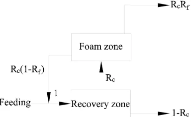
Some experts and scholars have proposed dynamic flotation models for countercurrent separation because the particles return from the foam layer to the pulp, as shown in Fig. 2. Based on this process, Finch and Dobby proposed the following expression to describe the recovery of the flotation column.
0
1
c f
c c f
R R
R
R
R R
=
− +
(1)
where
R
c is the collection zone recovery (%), andR
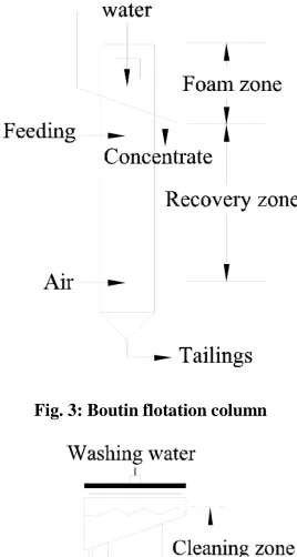
f is the foam zone recovery (%). [image:3.595.238.372.280.531.2]The representative countercurrent flotation column consists mainly of the Boutin flotation column (Fig. 3), Canadian Process Technologies Inc. (CPT) flotation column (Fig. 4), countercurrent contact flotation (CCF) column[3], and MTU-filled flotation column[4]. The height of countercurrent flotation columns is usually more than 10 m. The CPT flotation column is a Canadian product; the CCF was designed by the Changsha Engineering and Research Institute Ltd. of Nonferrous Metallurgy; and the MTU flotation column was invented by Professor Yang Jinlong of Michigan Technological University. The main difference between the CPT and Bourin flotation columns is their bubble generator. The CPT flotation column adopts the dismountable SlamJet® gas dispersion device. The MTU flotation column adds a specific filling medium in the traditional flotation column. This approach solves some of the problems in the conventional flotation column, such as the easy bubble coalescence and the easy production of a strong turbulence flow.
[image:3.595.238.372.363.655.2]Fig. 3: Boutin flotation column
Fig. 4. CPT flotation column
Cyclone Separation
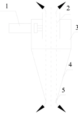
[image:4.595.239.371.120.322.2]The cyclone is one of the most basic applications of cyclone separation technology that has been introduced in the mineral flotation process. The cyclone separation principle is shown in Fig. 5. Some cyclone separation theories have been studied by previous scholars.
Fig. 5: Separation principle of the hydrocyclone
(1) feeding tube; (2) overflow tube; (3) cylinder, (4) cone; and (5) sediment export
In a gravitational field, the intensity of the force field is expressed by the acceleration due to gravity g, whereas in a centrifugal field, it is expressed by the centrifugal acceleration:
2
/
a
=
v
r
(2)where
a
is the centrifugal acceleration in m/s2,v
is the line speed of the radius of gyration in m/s, andr
is the gyration radius of the material point m.The ratio of a to g is called the centrifugal intensity and is represented by E.
2
/ (
)
E
=
v
rg
(3)The E of the conventional cyclone separation equipment can reach above l0 or even 100, and the precision and efficiency of the separation increase according to the density. The centrifugal intensity is easily changed by adjusting the feed pressure, but such adjustment cannot be achieved in the gravitational field.
The effect of the centrifugal field on the flotation column is mainly shown in the following aspects:
Improving flotation rate
The flotation rate constant[5] in the centrifugal field can be expressed as
2
3
b P rsec
(3
i/ 4
b)
k
=
πβ
R R U N
h
vt
R
(4)where Rb is the bubble radius, RP is the particle radius, Ur is the relative velocity between the particle and bubble, N
is the number of bubbles, ti is the flotation induction time, and β is the ratio of collision efficiency to adhesion
efficiency.
In the centrifugal field, when the bubble moves toward the center of the cylinder along the radial direction, the magnitude of velocity is given by
2 2 1 b
/ 9
When mineral particles move outward, the magnitude of velocity is given by
2 2
2
/ 18
v
=
ω
rd
∆
ρ
µ
(6)When the particles move in opposite directions, the relative velocity is given by
2 2 2
(
2
) / 18
r b
U
=
ω
r d
∆ +
ρ
R
µ
(7)where w is the angular velocity of rotation in rad/s, r is the rotation radius in m, and µ is the pulp viscosity in
kg/(m·s).
The induction time is calculated as follows,
3
4(
)
ln(
1)
(2 (
) )
b P i b r b P
R
R
t
P
P
R
U
R
R
+
=
+
−
+
+
(8)where P is the constant related to the flotation probabilities.
Based on the above equations, induction time is inversely proportional to Ur, and E is proportional to v. Therefore,
increasing E can help improve the relative velocity between the particles and bubbles, reduce the induction time between them, and improve the flotation rate.
Reducing the lower limit of the flotation particle
The inertia of fine particles is often ignored in the gravitational field because of their small mass. After the centrifugal force changes the equilibrium of forces acting on fine particles, the probability of bubble–particle collision is improved. The lower limit of the particle size[6] is
9
12
c bd
gR
ψη
ρ
=
∆
(9)where Ψ is the kinematic viscosity of particle and bubble in cm2/s, η is the viscosity of water in g/(cm· s), and ∆ρ is
the density difference between mineral particles and water in g/cm3.
Given their insufficient inertia, particles whose size is less than dc deviate from the bubble boundary streamline and
do not collide with bubbles.
Improving the flotation selectivity
The centrifugal force field expands the density difference between mineral-laden bubbles and fine mud; mineral-laden bubbles move toward the center and rise to the rough sections, and the entrained high-ash material is then cleaned continuously.
Typical cyclone flotation columns include the air-sparged hydrocyclone (ASH), centrifugal flotation cell (CFC), float-hydrocyclone (FH) flotation column, and circular centrifugal flotation cell.
The CFC was invented by Clean Earth Technologies. It was previously applied in oil-water separation and was later extended to froth flotation, particularly in high-sulfur coal sorting. In the flotation column, the impeller on the central axis mixes the slurry, and the spirals on the wall slow down the movement of the pyrite particles. The mineral-laden bubbles whose density is small move toward the center and rise to the foam layer. By contrast, the pyrite particles whose density is relatively great swirl along the column wall and are captured by spirals, until they are finally transported to the bottom of the cylinder.
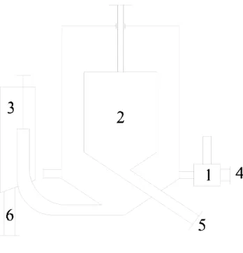
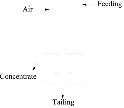
[image:6.595.239.373.229.481.2]The circular centrifugal flotation cell was developed by the Heilongjiang University of Science and Technology; its structure is shown in Fig. 7. The flotation machine is mainly composed of three parts: the bubble generator, sorting cell, and tailings[8]. The pulp is distributed uniformly across multiple external bubble generators and then enters the cyclone section along the tangential direction, as the cyclone force field of gas, liquid, and solid is formed. Under the combined action of centrifugal force and buoyancy, the mineral-laden bubbles spiral and form a relatively stable foam layer; flotation tailings rotate downward and are discharged from the tailings discharge device[9].
Fig. 6: ASH flotation cyclone
(1) overflow; (2) feeding; (3) aeration; (4) underflow
Fig. 7. Circular centrifugal flotation machine
(1) bubble generator; (2) concentrate tube; (3) tailings discharge device; (4) feeding; (5) concentrate; (6) tailings
Jet Mineralization
[image:6.595.219.393.517.698.2]Jet mineralization creates a high-turbulence environment for bubble–particle contact, provides the energy source for the entire flotation column, determines the energy state of the flotation column, and also provides the highest turbulent kinetic energy. A highly turbulent environment is beneficial for diffusing and mixing pulp and improving the recovery of fine minerals.
Typical jet flotation columns include the Jameson flotation column, jet flotation column, and contact cell.
The Jameson cell was developed by Professor G. J. Jameson of the University of Newcastle in 1987[10]. In its first industrial application in 1989, the Jameson cell was used as an alternative to the conventional column for base metal flotation by Mount Isa Mines in Australia. The success of this application paved the way for studies on coal applications[11]. The height of the industrial flotation column is only 1 m. It can be divided into three sections. Although it has a simple structure, the Jameson cell is a high-intensity and high-efficiency flotation device. In this technology, air is aspirated into the downcomer through the influence of the jet action caused by the highly pressurized pulp. This innovative flotation device can produce very fine bubbles without a compressor or an impeller mechanism.
Compared with conventional cells, the main advantages of the Jameson cell are its high production capacity, excellent separation ability, long mechanical life, flexible cell design, low capital, and low operating cost. A number of jet flow flotation columns inspired by this technology have subsequently emerged.
The KYZ flotation column was developed by the Beijing General Research Institute of Mining and Metallurgy. Its working principle is similar to that of the Jameson cell. A difference of the KYZ flotation column from the Jameson cell is that the former has a reflected false bottom at the base of the flotation column, which increases turbulent mineralization.
The jet flotation column, which was designed and developed by Dr. Jiang Z. W.[12,13], is mainly composed of three parts: the mixing tube, distributor, and separation tank, as shown in Fig. 8. Its structure is similar to that of the Jameson cell; however, unlike the Jameson cell, the bottom of its mixing tube is equipped with a distributor that ensures the even distribution of the mixed flow.
[image:7.595.202.413.571.755.2]In 1992, the Canadian Roger Amelunxen invented the contact flotation column (contact cell) shown in Fig. 9. The flotation contact cell is a slurry aeration device that consists of two non-moving parts: the contact and separation chambers. The slurry and air are fed into the contact chamber at a certain pressure, and the three-phase slurry flows into the separation chamber. The mineral-laden bubbles rise and form foam, while non-mineralized particles are discharged from the bottom. Its particle-bubble contact (mineralization) and separation chambers are completely separate, whereas those of other flotation columns are combined. However, the contact cell and other flotation columns all achieve the static separation of the foam. The particle-bubble contact and separation are two basic flotation processes, and each requires a different fluid environment. The particle–bubble contact requires strong turbulence, whereas the particle-bubble separation requires a static environment; these two processes are completed in the reactor and separator, respectively. If the two processes are achieved in one device, then the device is not conducive to their respective advantages. The contact chamber is a powerful bubble–particle contact device, and the turbulence of a separation chamber is small. This design not only improves the flotation rate but also reduces the cylinder height.
Fig 9: Contact cell
Multiple mineralization regimes
Countercurrent and Jet Flow
The representative flotation columns include the FXZ static, Microcel, LHJ, and other flotation columns.
The FXZ static flotation column was developed by the China University of Mining and Technology (Beijing)[14]. This flotation column can be divided from top to bottom into different separation zones: cleaning, feeding, recovery, inflating, and tailings zones. Each zone serves a different sorting function. The bubble generator adopts a cascaded form of Venturi tube and static mixers, and air is introduced through the high-speed jet flow[15,16].
The Microcel flotation column was developed in the United States, and it can be divided into three units that roughen, clean, and scavenge. Between the feeding inlet and the bubble generator is the collecting zone, which roughens. The mineralized bubbles rise to the foaming zone, which serves a cleaning function and removes the mixed gangue particles. When the circulating pulp flows through the bubble generator, air is adversely aspirated, and the uncollected hydrophobic particles come into contact with the bubbles again in a process called scavenging.
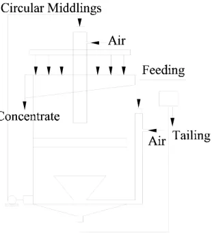
Developed by the University of Science and Technology in Beijing, the LHJ flotation column is based on the Jameson flotation column[17]. It is a new type of low jet flotation column; its structure is shown in Fig. 10.
Fig. 10: LHJ flotation column
Countercurrent, Cyclone, and Jet Flow
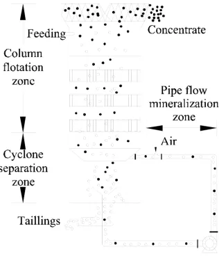
[image:8.595.230.385.496.671.2]column; the column consists of the column flotation, cyclone separation, and pipe flow zones. The column flotation zone is packed with sieve plates and vertical tubes to provide the necessary low-turbulence environment for roughening and cleaning. The cyclone separation zone is located below the flotation zone, where the centrifugal force field is strong. The pipe flow mineralization zone is connected to the cyclone separation zone along a tangential direction. The circulation system, which consists of externally circulating pumps, provides energy for the operation of the entire device.
Fig. 11: Separation principle of the FCSMC
The above-mentioned flotation columns represent the classic regimes. New regimes of columns have been developed, such as the mechanical flotation column, multi-stage flotation column, column flotation foam product re-cleaning, and other flotation columns, all of which are improved versions of the classic flotation columns.
CONCLUSION
In summary, the various methods of mineralization lead to different sorting effects. The contact modes of the particles and bubbles affect mineral flotation speed, carrying capacity, and energy consumption. At different stages of the flotation process, mineral particles have different floatability; different recovery methods should therefore be adopted. Generally, when the feeds have relatively better floatable mineral particles, a static environment should be adopted. As mineral floatability gradually worsens, relatively stronger energy should be used to recycle valuable minerals. Thus, compounding force fields and increasing sorting methods are the directions that must be pursued in developing future flotation columns.
Aacknowledgments
The Authors would like to thank the support from "Henan Key Discipline Open Laboratory of Mining Engineering Materials" (Grant No. MEM14-11), and “The doctoral foundation of Henan Polytechnic University” (Grant No. B2015-13) .
REFERENCES
[1] J Rubinstein. Metallic Ore Dressing Abroad, 1994, 32, 1-16.
[2] G Cheng; YJ Cao; HX Xu; XH Gui; ZP Lv, Coal Preparation Technology, 2011, 39(1), 66-70. [3] JW Wang; XJ Liu; XF Zhang, Modern Mining, 2011, 27(5), 109-112.
[4] JT Liu; XH Zhou; YT Wang; YJ Cao; J Guo, Coal Preparation Technology, 2003, 31(6), 25-33. [5] CS Shi; RX Ma; LG Tang, Clean Coal Technology, 2008, 14(5), 11-14.
[6] D Guo, Journal of Liaoning Technical University, 2002, 21(6), 702-704. [7] LY Chu; Q Luo, Metallic Ore Dressing Abroad, 1993, 31(11), 6-15. [8] YT Lv; JC Wang, Clean Coal Technology, 2009, 15(2), 28-31. [9] ZS Gao; LF Zhu, Clean Coal Technology, 1998, 4(4), 16-19. [10] CL Tao, China Mining Magazine,1995, 4(1), 43-48.
[11] H Hacifazlioglu; I Toroglu, Fuel Processing Technology, 2007, 88, 731-736.
[15] F Wang; MX Lu; ZP Zhang, Coal Preparation Technology, 1997, 25(1), 32-34.