International Journal of Emerging Technology and Advanced Engineering
Website: www.ijetae.com (ISSN 2250-2459, Volume 2, Issue 8, August 2012)399
A Novel Method of Using Twin-Rotor Axial Flux
Induction Machine for Wind Energy Conversion and the
Reactive power Compensation by TSC-TCR
V.Ramesh Babu
1, Dr.M.P.Soni
21Associate Professor, EEE Dept, VNRVJIET, Bachupally, Hyderabad
2Head & Professor, EEE Dept, MJCET, Hyderabad
Abstract—This paper proposes a new technique of using Axial Flux Induction Machines (AFIMs) for wind energy conversion systems. The Power Generation by wind is found to be enhanced by using a Twin Rotor Axial Flux Induction Machine (TRAFIM). By using Axial Flux Induction Machines, the gear box ratio can be reduced. The Single air gap and TRAFIM have been mathematically modeled in the environment of MATLAB and used for Fixed Speed Wind Energy Conversion Systems. TSC-TCR has been implemented for compensating the reactive power in the wind energy conversion system.
Keywords— FSWECS, Modeling, MATLAB, Reactive
Power Compensation, Twin Rotor Axial Flux Induction Machine, TSC-TCR.
I. INTRODUCTION
For many of years, on land wind farms are used to to harness electrical energy from the wind. But now a days the wind farms are shifted to offshore because of the of its stronger and heavier wind resource. Since the mechanical power produced from the wind is proportional to the cube of the wind speed, the slight increase in wind speed facilitates the turbine to harness more energy.Fixed Speed Wind Energy Conversion System (FSWECS) is viable for offshore application because of the steadier wind resource.
But there involves complexity in the design of the tower and foundation of the wind turbine in offshore: (i) the height of the tower should be more than that of the on land to reach the steadier wind resource (ii) the wind turbine is equipped with protection, control, and cooling components in addition to the main turbine components which adds weight to the nacelle. Gear box is the component which is the major contributer to the cost and weight of wind turbine.
The gear box can be eliminated by employing direct drives like permenent magnet synchronous generators and wound rotor synchronous generators along with the power converter interface for the variable speed wind turbine.But there is lot of uncertainity in the availability of permanent magnet materials. The demand is increasing very rapidly, mainly because these permanent magnets are also used in electric and hybrid vehicles. As a result, magnet prices are increasing. Because of this uncertainty in the availability and prices, these machines can be shelved soon in the wind industry [1].
International Journal of Emerging Technology and Advanced Engineering
Website: www.ijetae.com (ISSN 2250-2459, Volume 2, Issue 8, August 2012)400
The working principle involved in the axial flux machine is same as the radial flux machine. It differs only in its construction [3, 4] and the air gap flux direction. In conventional radial flux machines the conductors are placed in parallel and the direction of air gap flux is radial to the shaft axis where as in the axial flux machines the conductors are placed in radial to the shaft and air gap flux is parallel to the shaft axis.
In axial flux machines the stator has ring structure and rotor is disc shaped. The radial length from the from the stator inner radius to the outer radius is the active part to produce the torque and the axial length is dependent on the proper yoke design of the stator and the rotor i.e., the flux density in the stator and rotor yokes. Though the number of poles increases the active radial part of the machine remains unchanged and the axial length depends on the flux density in stator and rotor yokes [5]. When the ratio of motor overall length to motor external diameter > 1 then radial flux type is preferred and when it is < 0.3 axial flux type machine is preferred. Thus the axial flux machine has the flexibility in having higher pole number which let the machine to be an attractive alternative for the low speed applications [6]. Furthermore it has high efficiency, high power and torque densities and low rotor losses [7,5].
Usually these machines can have single or multiple air gaps. The multiple air gap axial flux machines have N stators and N+ 1 rotors for internal stator external rotor [ISER] type machines and N+1 stators and N rotors for external stator and internal rotor [ESIR] type machines. Because of its higher efficiency ISER type machine is preferred.
Based on the flux direction in the stator core the two topologies can be derived from ISER. One is North-North (NN) type topology and the other is North-South (NS) type topology and these topologies. Furthermore these are classified into Slotted type and Non Slotted type. In Non-Slotted type axial flux machine there is only NN type topology which consists of stator with tape wound iron core and windings wrapped around the core with back to back connections. Where as in Slotted type axial flux machine there are both NN type and NS type topologies.
Based on the above classification different types of permanent magnet synchronous machines and induction machines are derived. Axial flux Induction [AFI] machines are of slotted type. They can be either single air gap or multiple air gap. In single stator double rotor type structure the rotors can have (i) Two independent shafts driving two
different loads and hence two different speeds can be obtained at a time. (ii) Two rotors can share the same shaft enhancing the torque/power output.
Furthermore two different topologies are derived from slotted type based on the direction of main flux in the stator core as discussed earlier called Slotted NN-type AFI machine and Slotted NS-type AFI machine which are illustrated in the Fig.1.
(a) (b)
Fig.1- (a) Slotted NS-type AFI machine. (b) Slotted NN-type AFI machine
II. DETERIMINATION OF MACHINE PARAMETERS
A. Resistance Calculation
The resistance of winding is given by
---- (1) Where Resistivity of pure copper at 75o C is
Therefore the resistance can be expressed as
--- (2)
B. Inductances calculation
International Journal of Emerging Technology and Advanced Engineering
Website: www.ijetae.com (ISSN 2250-2459, Volume 2, Issue 8, August 2012)401
--- (3) Magnetizing inductance of stator nth phase winding is
--- (4) Where μo is the permeability of the free space and its value
is 4π x 10-7 H/m. L
ls is the leakage inductance of the nth phase
stator winding.Ntns is the number of turns in the nth phase
stator winding.
From the Fig.2, r2 and r1 are the stator core outer radius
and inner radius respectively and (r2-r1) gives the length of
the conductor. Where bs represents the width of the slot.
The dimensions are mentioned in the appendix, table I. The stator-to-stator mutual inductances for a balanced N Phase stator are given in (5).
--- (5)
Fig.2-Section of Stator surface.
And
--- (6)
Where k represents the kth stator phase and i ranges from 1
to N-k. Likewise the rotor self inductances, rotor to rotor mutual inductances can be determined.
Now the mutual inductances between stator and rotor phases can be given as.
--- (7)
Where θr is the angular displacement of rotor ks represents
kth stator phase k
r represents kth rotor phase.
And
--- (8)
Where Ntnr represents the number of turns in the rotor nth
phase winding
And also mutual inductance between kth stator phase and
(k+i)th rotor phase is given as
--- (9) And
--- (10) The obtained parameters from the above calculations are given in Appendix(Table II).
III.STEADY STATE TORQUE COMPARSION BETWEEN SINGLE ROTOR AND TWIN ROTOR AFIGS
A. Modeling of Single air gap Axial flux induction
generator
International Journal of Emerging Technology and Advanced Engineering
Website: www.ijetae.com (ISSN 2250-2459, Volume 2, Issue 8, August 2012)402
---- (11) The above equation is in the form
--- (12) The matrices [R], [Ls], [Lr], [Lsr] are obtained from the equations given in subsequent section
The generalized D-Q axes models are used for analyses of machines. Any particular reference frame model can be derived by substituting the appropriate frame speed and position in the generalized reference model. Reference frames rotating at an arbitrary speed are called arbitrary reference frames and other frames are particular cases of this arbitrary reference frame.
System equations in arbitrary reference frame can be represented in the matrix notation as
--- (13)
--- (14)
---
(15) Where p represents the differential operator .The transformation is done into synchronously rotating reference frame. This model is useful where the variables in the steady state need to be DC quantities. Some high performance control schemes use this model to estimate the control inputs. This model facilitates the simulation of vector control methods of induction motor.
In synchronously rotating reference frame model, the speed of the reference frame is ω. And (13) can be
represented in a state variable form as
--- (16) The above differential equation is solved by using Runge-kutta method in MATLAB to obtain the d-q axis currents of both stator and rotor. The simulation results are shown in Fig.3.
Fig.3. Stator and Rotor currents in synchronously rotating reference frame model
The electromagnetic torque is obtained by equation (17) and the simulation result is shown in Fig.4.
--- (17)
International Journal of Emerging Technology and Advanced Engineering
Website: www.ijetae.com (ISSN 2250-2459, Volume 2, Issue 8, August 2012)403
B. Modeling of Twin Rotor Axial Flux Induction
Generator (TRAFIG)
The axial flux induction machine consists of single stator sandwiched between two rotors. Since the machine considered here for the modeling is NN type AFIM, the flux path is in parallel with the shaft axis in the air gap and parallel and perpendicular to the shaft axis in the stator core.
The d-q axis voltage equations of twin rotor AFIG in synchronously rotating reference frame are given below.
The dq-axis flux linkages are given below
The matrix notation of the above set of voltage equations is given below.
--- (20)
Where resistance matrix is and inductance matrix are given below
(21)
--- (22)
To obtain the d-q axis currents of stator and rotor, (20) must be represented in the state variable form and simulate in the environment of MATLAB. The simulation results are shown below.
Fig.5. Stator and Rotor1currents in synchronously rotating reference frame model
Fig.6. Stator and Rotor2 currents in synchronously rotating reference frame model
(18)
International Journal of Emerging Technology and Advanced Engineering
Website: www.ijetae.com (ISSN 2250-2459, Volume 2, Issue 8, August 2012)404
The electromagnetic torque for the twin rotor axial flux induction machine is obtained by simulating the equation (23).The simulation result is shown in Fig.7.
--- (23)
Fig.7. Steady state torque in synchronously rotating reference frame
Therefore the torque is found to be doubled than with single rotor. And this analysis lets to investigate on the possibility of replacing the RFIG in the FSWECS with the medium speed TRAFIG so as to reduce the gear box ratio and enhance the power output.
IV. COMPARISON OF POWER OUT PUT OF RFIG AND
TRAFIG IN FSWECS
A. Equivalent circuit analysis of RFIG in FSWECS
To determine the operating and performance characteristics, an equivalent circuit analysis is required. The per phase equivalent circuit of three phase star connected four pole radial flux induction generator in a grid connected FSWECS is shown in Fig.8. The prototype machine parameters and grid specifications are mentioned in APPENDIX (Table II & III respectively).
Fig.8.Radial Flux SCIG equivalent circuit
The analysis starts with the calculation of equivalent impedance of the machine, proceeds with the calculation of stator current, apparent, real and reactive powers and then based on the required reactive power; the required capacitance at different slips is obtained as per the mathematical equations given below. Since the WECS is fixed speed the slip ranges between 0 to 1%.
The equivalent impedance is calculated and represented in the polar form
--- (24) Since the system is grid connected stator attains grid rated voltage and frequency across its terminals, the stator current can be calculated as follows.
--- (25) Stator power factor is
--- (26)
The apparent, real and reactive powers are calculated as follows.
B. Equivalent circuit analysis of TRAFIG in FSWECS
The analysis carried out for the FSWECS employing twelve pole twin rotor axial flux induction generator is same as the analysis carried out for RFIG. The equivalent circuit of TRAFIG is shown in the Fig.9.
The equivalent impedance
International Journal of Emerging Technology and Advanced Engineering
Website: www.ijetae.com (ISSN 2250-2459, Volume 2, Issue 8, August 2012)405
Fig.9.Twin rotor axial flux Induction Generator equivalent circuit
With the obtained equivalent impedance, the procedure repeats for the calculation of the apparent, real and reactive powers and power factor the further analysis carried out is same as discussed for the FSWECS with RFIG.
From the calculation of required reactive power from the grid to the induction generator, the required capacitance value is obtained from the below given analysis with which the reactive power compensation is achieved by connecting the capacitor across the stator terminals.
From the carried out analysis the power out of conventional induction generator and the twin rotor axial flux induction generator at different speeds is compared and the simulation results are shown in Fig10.
From the results it can be observed that for the same machine parameters, the power is enhanced twice to that of power generated by conventional induction generator with the adoption of twin rotor axial flux induction generator.
Fig.10.Comparision of power output of RFIG and TRAFIG
Furthermore the radial flux induction generator used in WECS is at most of four pole of speed 1500 rpm. To step
up the speed of turbine rotor around 6-20rpm to the higher speed of generator, a gear box of higher gear ratio is required, with which the weight and cost of the wind turbine increases and the system efficiency is decrease due to gear losses.. So, by employing medium speed generator like axial flux induction generator, a gear box with reduced gear ratio can be used with which the system efficiency is improved and cost and weight of the turbine is decreased.
V. REACTIVE POWER COMPENSATION FOR TRAFIG USING
TSCTCR
Thyristor Switched Capacitance Thyristor Controlled Reactor (TSC-TCR) is considered as reactive power compensation device for TRAFIG. It typically consists of „n‟ TSC branches and one TCR. Based on the required reactive power, the total number of TSC branches will be switched on and the firing angle of the TCR is adjusted to absorb the surplus reactive power if required.
From the analysis carried out in the section IV, the capacitance value varies from 9000 µF to 23000 µF in the proposed system. Therefore for capacitors of each 6000 µF are considered.
The inductor value is calculated by equating the reactive power of capacitor to the reactive power of the TCR when it is completely ON as given below
--- (29) Based on the required capacitance, the appropriate banks are on and if required, the surplus reactive power which is to be absorbed by the inductor is different at different speeds. The current through the reactor should be varied by delay angle control and the magnitude is obtained as given below.
--- (30) Thus for the required amplitude of current through the reactor, the firing angle of the TCR is obtained by solving the non-linear equation (31) in MATLAB using in built function fsolve.
International Journal of Emerging Technology and Advanced Engineering
Website: www.ijetae.com (ISSN 2250-2459, Volume 2, Issue 8, August 2012)406
The variation of ILF(α) with respect to firing angle
can be observed in the simulation result shown in the Fig.11.With the obtained firing angle the reactance of the TCR is represented as function of α as given in (3) for the equivalent circuit analysis.
--- (32)
Fig.11.Varition in fundamental current magnitude through TSCTCR with the firing angle α
The obtained TSCTCR model is now connected across the stator terminals and the equivalent circuit analysis is carried out to show the unity power factor. The equivalent circuit of TRAFIG with TSCTCR across the stator terminals is shown in Fig.12.
Fig.12.Twin rotor axial flux Induction Generator equivalent circuit including TSCTCR across stator terminals.
The equivalent circuit analysis is same as the procedure involved in section V and the simulation results are shown below.
Fig.13.Reactive power compensation by TSCTCR
Fig.14.Powerfactor improvement by TSCTCR
Fig.15.Real, apparent and reactive powers using TSCTCR
VI. CONCLUSION
International Journal of Emerging Technology and Advanced Engineering
Website: www.ijetae.com (ISSN 2250-2459, Volume 2, Issue 8, August 2012)407
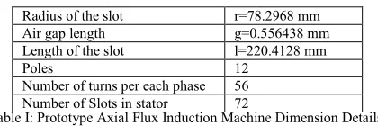
[image:9.612.65.275.170.240.2]APPENDIX
Table I: Prototype Axial Flux Induction Machine Dimension Details
Table II: Obtained parameters of Prototype Axial Flux Induction Machine
Stator Resistance 1.102 mΩ
Rotor Resistance 1.497 mΩ
Stator Leakage Inductance 0.0649 mH
Stator Magnetizing inductance 2.1346 mH
Stator Self Inductance 2.1995 mH
Rotor Leakage Inductance 0.0649 mH
Rotor Magnetizing Inductance 2.1346 mH
Rotor Self Inductance 2.1995 mH
Stator-Rotor Mutual inductance 2.1346 mH
Table III: Rated Parameters of TR AFIG in Grid connected FSWECS
Grid Rated Voltage(Line voltage) 440 V
Frequency 50 Hz
Rated Slip -0.008
Rtaed Power 2 MW
References
[1] Polinder.H,”Overview of trends in wind turbine generator system”,
power and energy society general meeting, 2011,IEEE, Conference publications.
[2] Metin Aydin, S Huang,, Thomas. A.Lipo, “A new Axial Flux surface mounted permanent magnet machine capable of field control”, Industry application conference, 2002, 37th IAS Annual meeting,
conference record, Volume: 2, 2002.
[3] Z.Zhang, F.Profumo and Tenconi, “Axial flux versus Radial flux PM
machines,”Electromotion, Vol.3, pp, 23-29, 1996.
[4] Andrea Cavagnino, Mario Lazzari, Francesco Profumo and Alberto
Tenconi,” A comparison between the Axial Flux and Radial Flux
Structures for PM synchronous Motors”, Industry application
Conference, 2001. 36th IAS annual meeting, conference record of the
2001 IEEE
[5] V.B.Hosinger, “Sizing equations of electrical machinery” IEEE
trans.Energy Conversion, vo;.EC-2,pp, 116-121, Mar. 1987.
[6] F. Caricchi, F. Crescimbini, E. Santini, “Axial-Flux Electromagnetic
Differential Induction Motor”, Electrical Machines and Drives, IEE
Conference Publication, No. 412, September 1995.
[7] S.Haung, J.Luo, F.Loenardi and T.A.Lipo, “A comparison of power
density for axial flux machines based on the general purpose sizing equations”. IEEE tarns. Energy conversion, vol.14, pp.185-192, June 1999.
[8] H.A.Toliyat, Thomas A.Lipo , J.coleman White, “Analysis of concentrated winding induction machine for adjustable speed Drive Applications.”, IEEE Transactions on energy conversion,Vol.6, N0.4, December 1991.
[9] Hecker.Q, Igelspacher,I.; Herzog,H.-G,”Parameter identification of an axial flux induction machine by winding functions”, „Electrical machines (ICEM), 2010 XIX international conference on 6-8 sep.2010.
REFERENCE BOOKS
[10] Dr.M.Ramamoorty, „A Short Course on Electrical Machines‟ published by ERDA, Vadodara, 2006
[11] P.C.Krause, Oleng Wasynczuk, Scott D. Sudhoff, „Analysis of
electric machinery and drive systems‟. Second edition, A John Wiley & sons, Inc publication, 2004.
[12] Chee Mun Ong,„Dynamic simulation of electric machinery’, Prentice
Hall PTR, Upper saddle river, New Jersey, 07458, 1998.
[13] Philip L. Alger,„Induction machines their behavior and uses‟ Second
edition, Gordon and Breach Publishers,
[14] R.Krishnan, „Electric Motor Drives Modeling, Analysis and Control‟
Pearson Education Pte.Ltd, 2001.
[15] Bin Wu, Yongqiang Lang, Navid Zargari, Samir Kouro, „Power
Conversion and Control of wind energy systems‟, A John Wiley & sons publications.
Radius of the slot r=78.2968 mm
Air gap length g=0.556438 mm
Length of the slot l=220.4128 mm
Poles 12
Number of turns per each phase 56