Crashworthiness Behavior of Hollow Al-Based Functionally Graded
Material (FGM) Box under Quasi-Static Loading
S. Jamian
1, a, M. R. Zainal Abidin
2,band A. M Muda
3,c 1Department of Engineering Mechanics, Universiti Tun Hussein Onn Malaysia, Parit Raja, Batu Pahat 86400 Johor, MALAYSIA
2
Center for Graduate Studies, Universiti Tun Hussein Onn Malaysia, Parit Raja, Batu Pahat 86400 Johor, MALAYSIA
3
Faculty of Mechanical and Manufacturing Engineering, Universiti Tun Hussein Onn Malaysia, Parit Raja, Batu Pahat 86400 Johor, MALAYSIA
[email protected], b [email protected], c [email protected]
Keywords: Aluminum (Al), Crash box, Functionally graded material (FGM).
Abstract. This study aims to investigate the crashworthiness behavior of hollow Al-based functionally graded material (FGM) box. In order to introduce the concept of FGM, several holes are known as trigger points were drilled on a thin-walled Al column. The column was divided into four segments and each segment has a different number of trigger points. The difference number of trigger points on each segment produces the different structural strength. Quasi-static loading test was conducted in order to observe the deformation pattern occurred. The corresponding graph of force versus distance then was analyzed to obtain the value of energy absorption for each sample. Five samples of different segment arrangement were tested, namely, S1a, S1b, S2, S3 and S4. From the results obtained, the sample S1b give the best results with the highest value of energy absorption. This sample is designed with a large number of trigger points in the first segment, followed by a reduced number of trigger points until the end of the segment. The quality of crash box can be improved by introducing FGM concept. This type of crash box is able to produce a grade of absorption crushing energy. Thus it can reduce severity of injury during an accident.
Introduction
Nowadays, the most of structural components of sea, land and air vehicles are designed as thin-walled structures [1]. Among the advantages used thin thin-walled structures are high strength to weight ratio and usually called as crash box. Crash box serve as an active and passive safety device.
Usually, a crash box is equipped several crash beads functionally for easily to collapse and buckling deformation. There are more than ten fundamentally different front-end crash boxes pattern have been developed [2]. The crash box pattern appearances are different depends on the types of automobile and ability energy absorption. However, the productions of complex pattern often complicate the installation process crash box on the front of the automobile.
Concept of functionally grade material (FGM) is introduced by a group of Japanese scientists in year 1980 [3]. FGM refer the composition and structure gradually changes over volume, resulting in corresponding changes in the properties of the material [4]. FGM is used in many fields such as medical, defense, aerospace and sports. In this study, the concept of FGM is applied for crash box development in transportation. In automobile industry, a car is designed with energy-absorbing systems to reduce injury of car passengers in high speed-collisions and the damage of car in low-speed collisions. The main purpose introduce FGM in producing crash box is to easily simple design the crash box without reduce the quality of energy absorption [5] and to install in the automobiles.
each sample of Al FGM crash box. Energy absorption of FGM crash box produced in this study is expected to be much larger than the crash box is not the concept of FGM.
Materials and experimental
[image:2.595.60.547.179.472.2]The parameter of geometric model (Fig. 1) shows in Table 1 was fabricated from pure Al with thickness of 2 mm. The crash box with 280 mm height was separated to four segments, namely, I, II, III and IV. Table 2 shows the number of triggers applied for the crash box.
Table 1: Parameter of crash box model
Length, A (mm) 25
Wide, B (mm) 50
Height, L (mm) 280
Thickness, T (mm) 2 Density, ρ (kgm-3
[image:2.595.78.537.189.308.2]) 2700
Fig. 1: Schematic of geometry
Table 2: Number of trigger points
Segment S1a S1b S2 S3 S4
I ─ 50 20 20 20
II 20 30 ─ 30 30
III 30 20 30 ─ 50
IV 50 ─ 50 50 ─
Material properties and specimen preparation. In this study, the simple shape of crash box, rectangular in cross-sectional area, was selected. Figure 1 shows the geometry of crash box for quasi-static loading. Five different types of crash box, namely S1a, S1b, S2, S3 and S4, were impacted.
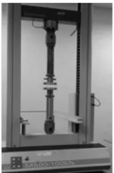
Quasi-static loading setup. The experimental quasi-static tests were performed using a Universal Testing Machine (UTM) model Testometric M500 hydraulic machine that has a capacity of 100 kN (Fig. 2). The machine has been operated with a constant feed rate of 5 mm/min and a maximum displacement of 200 mm (successive compression), being the quantitative information acquired by the machine software. The specimen column has been placed centrally in the test machine, without any further support.
Fig. 2: UTM model Testometric M500 Fig 3: Stages in behavior of thin-walled column [6] I II III IV
[image:2.595.304.514.606.735.2] [image:2.595.117.200.610.735.2]Deformation of crash box. Figure 3 shows three phases deformation of thin-walled column subjected to a quasi-static axial loading. From point O–E show the elastic range of uniform compression column, increase to point A (corresponds to onset of global bending). Eulerian buckling occur when crossing at point A. The onset of local collapse mechanism from point A-B. The failure mechanism characteristic begin after corresponds point B for the geometrical parameters of the thin walled column. If deformation begins in the middle section of a column, progressive collapse will occur [6].
Specific energy absorption prediction. In this study, the energy absorbing capability is estimated by the specific energy absorption (SEA) of crash box which can be calculated by:
(1)
Here, Pmean is average compression force, δ is compression displacement; ρ is density, A is cross-sectional area and L is initial height of crash box.
Results and discussions
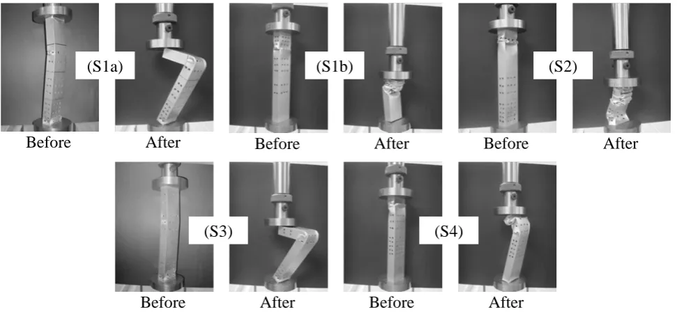
There were five samples subjected to an axial quasi-static loading test. Each sample was placed between two flat plates on the machine Universal Testing Machine (UTM) Testometric model M500. Figure 4 shows the deformation pattern of the crash box after under quasi-static loading, respectively.
Before After Before After Before After
[image:3.595.56.542.361.585.2]Before After Before After
Fig 4: Deformation of crash box model under quasi-static loading
Based on the Fig. 4, there are two types of failures on the AL FGM crash box under axial quasi-static loading; bending (S1a and S3) and crush failures (S1b and S2). Bending failure (S1a and S3) occurs is due to the sample surface at the both end section are not flat and imbalance position when subjected to the load. Sample S1b and S2 produce the uniform crush. The crushing initially occurs early in the first segment with holes trigger. This is consistent with the results of a study conducted by Shariati et. al [7] and B. Bartczak et al [8], which stated that the crushing easily to occur on the surface area of a hole trigger. When the triggers holes added for each segment, then the material strength are decreases. However, gradually crushed deformation from segment to another segment for S1b sample produces good results in the production of a crash box.
Figure 5 shows the force-displacement curves of the FGM crash boxes model with different trigger holes method under the quasi-static loading. The load fluctuates throughout the collapse. Although the composition of materials is the same in all crash boxes, their load-displacement curve is different. As can be observed, there are almost no difference in the value of the first buckling load
(S1a) (S1b) (S2)
for all crash box model. The impact energy absorption increase and ensuring high buckling load of the crash box model [9]. Table 3 shows the maximum force based on the Fig. 5. Sample S2 produce the maximum force (14.080 kN) compare the others sample.
Table 3: Peak crush force
Sample Pcr (kN ) Displacement, δ (mm)
S1a 13.160 2.1305
S1b 13.250 1.9352
S2 14.080 1.9525
S3 13.440 1.6875
Fig. 5: Force-displacement curves S4 13.860 1.9797
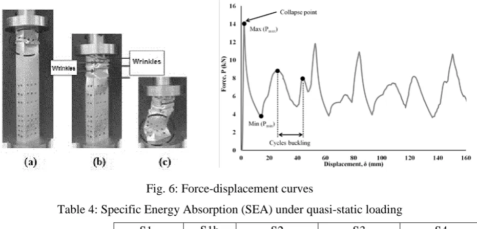
[image:4.595.73.539.446.670.2]Figure 6 show deformation and graph for the sample 2. In the elastic stage, the sample can be returning to the original height. When the addition of compression force increased until the maximum force of elastic, the first fold started to forming, the sample reaches the first maximum peak force capacity. This can be seen in the graph is going to rise up to the peak load. The load decreases as the first fold is being forming where the folding outward is started and changes in the sample cause it to fail back to the original shape. After the completion of the first fold, the force begins decrease to a minimum level where the contact outward happened. After that, the further deformation causes the load to increase until the next peak is formed with the formation of the second fold [10].
Fig. 6: Force-displacement curves
Table 4: Specific Energy Absorption (SEA) under quasi-static loading
S1a S1b S2 S3 S4
SEA (kJ/kg) 0.128 1.081 0.877 0.164 0.400
Conclusions
This paper presents experimental results the high energy absorption of FGM crash box samples under quasi-static loading with the purpose of inducing modification of material properties. This is achieved using trigger holes method. The strength of segments change with differentiation of the trigger holes parameters. The quasi-static tests presented to determine the maximum SEA for all tested sample. From the experiment results, the specific energy absorption of Al FGM crash box fabricated under quasi-static are successfully calculated. The S1b sample is the best crash box compares the other sample. The arrangement of triggers hole determine the maximum force and SEA crash box.
Acknowledgement
The authors would like to acknowledge Universiti Tun Hussein Onn Malaysia (UTHM) for funding this project.
References
[1] W. Abramowicz. Thin-walled structures as impact energy absorbers. Thin-Walled Struct. 41 (2003) 91–107.
[2] P.Schwanitz, D. Göhlich, W.J. S. Werner, J. Zerbe. A New Methodology for Robust Optimization of Vehicle Structures, in online prosiding of 4th International Conference on Impact Loading of Lightweight Structures 2014, Jan 12 – 16, Cape Town.
[3] R. M. Mahamood, E. T. Akinlabi, M. Shukla and S. Pityana. Functionally Graded Material: An Overview. Proceedings of the World Congress on Engineering 2012 Vol III WCE 2012, July 4 – 6, 2012, London.
[4] Y. Miyamoto, W.A. Kaysser, B.H. Rabin, A. Kawasaki, R.G. Ford. Functionally Graded Materials: Design, Processing and Applications, Kluwer Academic Publishers, 1999.
[5] P. Hosseini Tehrani1, M.Talebi. Stress and Temperature Distribution Study in a Functionally Graded Brake Disk, Int. J. Auto. Eng. 2(3) (2012) 172 – 179.
[6] W. Abramowicz, N. Jones: Transition from initial global bending to progressive buckling of tubes loaded statically and dynamically, Int. J. Impact Eng. 19(5–6) (1997) 415 – 437.
[7] M. Shariati, H. R. Allahbakhsh, J. Saemi : An experimental and numerical crashworthiness investigation of crash columns assembled by spot-weld, Mechanika Nr 2(82) (2010) 21 – 25.
[8] B. Bartczak, D. Gierczycka-Zbrożek, Z. Gronostajski, S. Polak, A. Tobota. The use of thin-walled sections for energy absorbing components: a review. Archives of Civil and Mechanical Engineering X(4) (2010) 5 – 19.
[9] Y. Nakazawa, K. Tamura , M. Yoshida, K. Takagi, M. Kano. in Onate, E.,Owen and D.R.J. (Eds.): Proceedings of the VIII International Conference on Computational Plasticity (COMPLAS VIII), Barcelona (2005) p. 167.