International Journal of Emerging Technology and Advanced Engineering
Website: www.ijetae.com (ISSN 2250-2459,ISO 9001:2008 Certified Journal, Volume 3, Issue 5, May 2013)
232
Real Power Loss Allocation Based on Circulating Current
between Generators
Maulik J. Patel
1, Maulik V. Patel
2, Janak Sorathiya
31Assistant Professor, SITG, Tajpur, Gujarat 2,3Assistant Professor, SSESGI, Rajpur, Gujarat
Abstract - This paper present a loss allocation method based on circulating current theory. Transmission loss allocation is based on separation of load loss and circulating current loss. A load loss due to line flows caused by load currents, this part will be referred to as load loss. The second part is due to the circulating current resulting from differences in generator voltages. Being caused by mismatch in generator’s voltages, this part will be referred to as no load losses or circulating current loss. This paper presents an algorithm to obtain a load loss, circulating current loss, and circulating power between two generators. Examples with a 5-bus and IEEE-30 5-bus system are illustrating calculation strategy. Test result shows that method can be satisfy the load flow result.
Keywords- Transmission loss allocation, load loss, circulating current loss.
I. INTRODUCTION
Since 1980, the electricity supply industry has been undergoing restructuring or deregulation which introduces open electricity market for trading electricity between generators and suppliers in competitive environments [1]. This transformation consists of two aspects that are related to each other, which are restructuring and privatization. Restructuring is a change in structure of commercial arrangements in selling energy. Meanwhile privatization is a change of ownership from the government to the private sector that helps create choices and competition.
Due to this change some problems and challenges have risen. One of these problems is the transmission loss allocation. Transmission loss allocation is not an easy task. Even in a simple two node system with one generator supplying a single load, loss allocation between the generator and the load has to be agreed upon as there is no physical measurement or mathematical method that determines the loss shares in a unique manner. In a real system, matters get more complicated because of two facts. The first is that the determination of the line flows caused by each load through each transmission line has a good degree of arbitrariness.
The second is that the transmission line loss is a nonlinear function of the line flow, and hence cannot be separated between partial flows through the same line in a unique convincing way. The difficult task is to selecting a loss allocation method due to absence of a standard means for comparing the different methods. Based on fair and equitable practice, any loss allocation algorithm should have most of the desirable properties stated below [2].
To be consistent with the results of power flow solution,
To provide appropriate economic signals,
To be easy to understand,
To be simple to implement,
To depend on the relative location in the transmission network,
To avoid volatility.
A number of loss allocation schemes have been presented to allocate the system losses to generators / loads in a pool market or to individual transactions in a bi-lateral contracts market. Based on different assumptions and approximations there are mainly three families of schemes: Proportional sharing procedures [3]-[4], Pro rata methods [2], Incremental transmission loss (ITL) methods [5]-[6].
International Journal of Emerging Technology and Advanced Engineering
Website: www.ijetae.com (ISSN 2250-2459,ISO 9001:2008 Certified Journal, Volume 3, Issue 5, May 2013)
233
Another method used in pool markets is the Incremental transmission loss (ITL) allocation which is based on Incremental transmission loss coefficient. In this method the allocation depends on the choice of the slack bus. The paper [5]provides analyses and test results from a practical implementation of an incremental allocation procedure in the Norwegian electric system. The paper [6] solves a system of differential equations by using numerical integration where a distributed slack bus concept is used. The ITL methods depend on the selection of the slack bus and also the slack bus is allocated with no losses. Another loss allocation method is based on the bus impedance Z-bus matrix [7] and allocates transmission losses among loads and generators assuming a pool dispatch. A natural separation of the system losses among the network buses is derived using the loss formula. It does not however account for the interaction between different injections. In [8] and [14], on the bases of complex conjugates of individual current injection calculate losses through the branches. Due to the appearance of the branch reactance loss allocation is unreasonable.
In this paper present a method for transmission loss allocation is based on separation of the transmission losses into load losses, caused by the flow of load currents only, and circulating current losses caused by the differences in voltages at the generation nodes. This is the advance method for transmission loss allocation. This method is also useful for allocating losses in between particular loads and generators. This method is simple and more flexible.
II. BASIC CONCEPT AND THEORIES
When two or more generator sets are operated in parallel, a current may circulate between the generators. This current will exist when the internal voltage generated by each generator is slightly different; current will flow out the line leads of one generator, through the paralleling bus and into the second generator. It does not flow into the load, this current, called “circulating current”. A loss produce due to circulating current is called circulating current loss. So the circulating current is also important for consideration for loss allocation method [15].
Transmission loss is decomposed into two components. The first is due to current flow from generators to loads. The second is due to the circulating current between generators.
Let’s take an example of a DC system, which is given in the figure 1. In figure one load bus is given. There are two lines which have resistance r1 and r2 respectively. The current I1 and I2 are supply the load. The load current is IL and node voltage are V1 and V2.
Fig.1: 3-bus dc system
Now, by applying current divider rule
I1 = . IL +
(1)
I2 = . IL
(2)
Due to the resistance r1 and r2, the power loss produce in line 1 and line 2 is given by,
(
) , (3)
( )
(4)
The total loss is the summation of the individual line losses in the two lines.
(5)
The equation (5) shows the total loss, which containing two terms; first term shows that load loss and second term shows the circulating current loss. A 3-bus ac system is shown in figure 2. It is same like dc system but with all the physical parameters and quantities are complex forms.
That means the line impedances, voltages and currents are in complex quantities. In 3-bus AC system the voltage difference between source node 1 and node 2 with angle δ is V1-V2 = V .
Fig.2: 3-bus ac system
Applying the same rule of DC system the total power loss in 3-bus AC system can be given from the following equation.
= | |
| | +
| |
| |
V1 V2
IL
I1
V I2
V r2
V1 V2
International Journal of Emerging Technology and Advanced Engineering
Website: www.ijetae.com (ISSN 2250-2459,ISO 9001:2008 Certified Journal, Volume 3, Issue 5, May 2013)
234
+ | || | || | |. . (6)
The equation (6) shows the total loss, which containing three terms; the first term is the load loss, the second term is show the circulating current loss and the third term shows the impedance mismatch loss. If the X/R ratio of the two lines are same so θ1 = θ2 = θ and third term will be cancel out.
=| | | | |
| +
| |
| | (7)
III. MATHEMATICAL EQUATION &FORMULATION
A. Calculation of Transmission Losses:
Transmission loss is divided in two parts are following: 1) Load loss
2) Circulating current loss
1) Load Loss:
Loss due to load currents are obtained by assuming that all generators act as ideal voltage sources with no circulating currents between them [16].
Now power system equation can be given by proper partitioning of YBUS, it can be written in bellow equation.
I=Y V (8)
[
] [
] [ ] (9)
IG, VG are the current and voltage vectors for generator nodes respectively. Similarly IL, VL are the current and voltage vectors for load nodes respectively. YGG is the self-admittance matrix of generator nodes, YGL is the mutual admittance matrix between generator and load nodes, YLG is the mutual admittance matrix between load and generation nodes, YLL and is the self-admittance matrix of load nodes.
IG = YGG VG + YGLVL
(10) IL = YLG VG + YLL VL
(11)
To calculate the current flow through branches due to loads are determined while VG set to zero in equation (11). In this condition, the equation of the load node voltages will be
VL = ZLL IL (12)
The generator node voltage is calculated by equation,
VG = IL (13)
Here, NG is the number of generator nodes and NL is the number of load nodes,
The branch currents due to loads can be calculated as bellow:
= [ ] [ ] (14)
Here, is the branch admittance matrix, in which main diagonal elements are present. AT is transpose of the node to branch incidence matrix. To find the individual load current, the current column is replaced by diag(IL), which is a diagonal matrix having load currents as its main diagonal elements
[ ] = K. [ ]
(15)
Where,
K= [ ] [ ][
]
K is the load current distribution factors matrix, where
is the fraction of the current of load L that flows through branch b, that is, = .
The size of the matrix [ ] is row equal to number of branches and column is equal to number of loads. The summation of each row gives the total branch current
[
]
due to all loads. The power loss of branch i having resistance r due to load current at node j is given by,= [ ] • [ ] (16)
Where,
= Power loss in branch i due to load at node j,
= Current through branch i due load at node j,
= Current through branch i due to all loads, • = Dot product of a vector defined as follows:
• = ( ) ( )
= real part of an expression = imaginary part of an expression
2) Circulating Current Loss:
In equation (9) load current set to zero, so the generator circulating current is obtained and the generator voltage is obtained from the power flow solution. The generator circulating current is calculated using equation,
[ ] = [[YGG]
-
[YGL].[YLL]-1.[YLG]][VG] (17)The voltage vector of load nodes is determined as,
International Journal of Emerging Technology and Advanced Engineering
Website: www.ijetae.com (ISSN 2250-2459,ISO 9001:2008 Certified Journal, Volume 3, Issue 5, May 2013)
235
The node voltage vector can be expressed in terms of the generator circulating current as,
[ ]=[
] [
] (19)
Where,
[ZGG]= [[YGG]-[YGL] [YLL]-1.[Y LG]]-1 (20)
Due voltage difference between two generators the current circulate between them given by,
[ ] [ ][ ] [
].diag[
] (21)
The size of the matrix [ ] is row equal to number of branches and column is equal to number of generators. The summation of each row gives the total branch current
[
]
due to all generators. The power loss due to generator circulating currents is given by,= [ ] • [ ] (22)
Where,
= Power loss in branch i due to generator at node j, = Branch current due to the generator's circulating
current,
= Current through branch i due to all generator's, • = Dot product of a vectors
B. Contribution of Generator in Transmission Loss: The circulating power is calculate by following equation
Pcir(i) = (VG(i).I*cir(i)) (23)
The sum of the generators circulating powers is gives the circulating power loss, Pc
∑ (24)
By using equation (23) and (24) calculate the share of generator i, in the circulating current loss can then be calculated as follows:
PG(i)
| |
|∑ | Pc (25)
IV. FLOW CHART
Obtain load flow solution for the system
Partition system Y-bus matrix according to eq. (9)
Obtain the generator current and load current from eq. (10) and (11)
Start
Calculate branch currents due to load currents by using eq. (14)
Calculate the power loss Δ in branch i due to load at node j by
International Journal of Emerging Technology and Advanced Engineering
Website: www.ijetae.com (ISSN 2250-2459,ISO 9001:2008 Certified Journal, Volume 3, Issue 5, May 2013)
[image:5.612.39.291.148.619.2]236
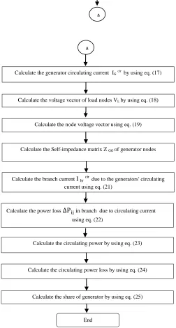
Fig.3: Flow chart of real power loss allocation method
V. TEST SYSTEM
A. 5-bus system
The simple 5 bus system with bus and line data is shown in table I and II. In the proposed method separating load losses and circulating current losses.
[image:5.612.304.578.176.715.2]A computer program has been written in MATLAB 7.2 to calculate load loss, circulating current loss, and circulating power between two generators.
Fig.4:5- Bus test system
Table I
BUS DATA FOR THE 5 BUS SYSTEM
Bus No
Bus Type
Generation Load
Voltage (pu) P
(MW) Q (MVAR)
P (MW)
Q (MVAR)
1 Slack --- --- 0 0 1.06
2 PV 40 0 0 0 1.045
3 PQ 0 0 20 15 1.0
4 PQ 0 0 50 30 1.0
5 PQ 0 0 60 40 1.0
Table II
LINE DATA FOR THE 5 BUS SYSTEM
Line
R(pu) X(pu)
From To
1 2 0.02 0.06
1 3 0.08 0.24
2 3 0.06 0.18
2 4 0.06 0.18
2 5 0.04 0.12
3 4 0.01 0.03
4 5 0.08 0.24
G 1
G 2
Load 1
Load 2
Load 3
1 3 4
5 2
A
A
Calculate the generator circulating current IGcir by using eq. (17)
Calculate the voltage vector of load nodes VL by using eq. (18)
Calculate the node voltage vector using eq. (19)
Calculate the Self-impedance matrix Z GG of generator nodes
Calculate the branch current I br cir
due to the generators' circulating current using eq. (21)
Calculate the power loss Δ in branch due to circulating current
using eq. (22)
Calculate the circulating power by using eq. (23)
Calculate the circulating power loss by using eq. (24)
Calculate the share of generator by using eq. (25)
International Journal of Emerging Technology and Advanced Engineering
Website: www.ijetae.com (ISSN 2250-2459,ISO 9001:2008 Certified Journal, Volume 3, Issue 5, May 2013)
237
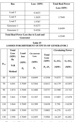
Table III
LOSS ALLOCATED BY EACH LOAD AND GENERATOR FOR 5 BUS SYSTEM
Bus Loss (MW) Total Real Power
Loss (MW)
Load 3 0.4633
3.7049
Load 4 1.2629
Load 5 1.9787
Generator 1 0.4273
0.8499
Generator 2 0.4226
Total Real Power Loss due to Load and
[image:6.612.41.298.161.580.2]Generator 4.5548
Table IV
LOSSES FOR DIFFERENT OUTPUTS OF GENERATOR 2
PG2
Total Loss (MW)
By
N-R
Method Load
loss
(MW)
PL
Cir.current Loss
(MW)
PC
Total Loss (MW)
PL+PC
Circulating Power
G1G2
(MW)
G1G2
(MW)
40 4.555 3.7049 0.8499 4.5548 74.875 -74.036
70 4.041 3.7049 0.3364 4.0413 44.179 -43.853
90 3.874 3.7049 0.1688 3.8737 23.900 -23.743
100 3.841 3.7049 0.1367 3.8416 13.803 -13.678
110 3.844 3.7049 0.1389 3.8438 3.758 -3.6230
120 3.880 3.7049 0.1753 3.8802 -6.270 6.435
130 3.950 3.7049 0.2455 3.9504 -16.247 16.482
The table III shows the loss allocated by each load and generator separately. This is the one advantages of this method to loss allocate individual load and generator. In table IV shows the different loss for different output of generator 2, at that time load keep constant. By analysis of table IV, it is shows that when PG2 is 40 MW, the load loss is 3.7049 MW and circulating current loss is 0.8499 MW and circulating power is 74.875 from generator G1 to G2. This two loss gives total system loss is 4.5548 MW.
The total loss obtain from this method is same as total loss obtain by N-R method, which is the proofs the accuracy of this method. PG2 is increase up to 130 MW, at that time circulating power is 16.482 MW circulate from bus 2 to 1. When PG2 is 100MW then minimum circulating current loss will be occurs is 0.1367MW. The variation of the circulating current loss and circulating power with changes the generation, but load loss is the constant. It is independent of the generator outputs, which approve the validity of this method.The small difference between the total loss calculated and loss due to circulating power is due to the difference in voltage magnitude. This difference causes a reactive power to flow in the system causing active power loss.
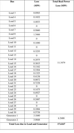
B. IEEE 30-BUS SYSTEM
[image:6.612.312.575.374.709.2]The IEEE 30-bus System is used to show the effectiveness of the method. Its diagram and the related parameters are given in [18]. The IEEE 30-bus System is consists of two generators and 4 synchronous condensers.
TABLE V
LOSSES FOR DIFFERENT OUTPUTS OF GENERATOR 2
PG2
Total Loss (MW)
By N-R Method
Load Loss (MW)
PL
Cir.Cu rrent Loss (MW)
PC
Total Loss (MW) PL+PC
Circulating Power
G1G2
(MW)
G2G1
(MW)
55 17.603 11.347 6.269 17.616 202.916 -196.621
57 17.488 11.347 6.157 17.504 200.789 -194.605
60 17.318 11.347 5.992 17.339 197.601 -191.582
62 17.207 11.347 5.883 17.230 195.477 -189.567
64 17.097 11.347 5.776 17.122 193.354 -187.556
66 16.988 11.347 5.671 17.016 191.233 -185.536
International Journal of Emerging Technology and Advanced Engineering
Website: www.ijetae.com (ISSN 2250-2459,ISO 9001:2008 Certified Journal, Volume 3, Issue 5, May 2013)
[image:7.612.43.295.169.621.2]238
Table VI
LOSS ALLOCATED BY EACH LOAD AND GENERATOR FOR IEEE 30-BUS SYSTEM
Bus Loss
(MW)
Total Real Power
Loss (MW)
Load 3 0.0503
11.3479
Load 4 0.1832
Load 5 4.4033
Load 6 0
Load 7 0.9860
Load 8 1.3466
Load 9 0
Load 10 0.1690
Load 11 0
Load 12 0.3255
Load 13 0
Load 14 0.2075
Load 15 0.3015
Load 16 0.1162
Load 17 0.3304
Load 18 0.1325
Load 19 0.4138
Load 20 0.0872
Load 21 0.7238
Load 22 0
Load 23 0.1475
Load 24 0.4927
Load 25 0
Load 26 0.2487
Load 27 0
Load 28 0
Load 29 0.1084
Load 30 0.5738
Generator 1 3.1840
6.2688
Generator 2 3.0848
Total Loss due to Load and Generator 17.6167
VI. CONCLUSION
This paper presents a new method for transmission loss allocation and develops programmed to calculate load loss, circulating current loss, and circulating power between two generators. The benefit of the algorithm is also used to allocate loss in between particular loads and generators.
This new method tested on 5 bus system and result compared with N-R method, after this method applied on IEEE 30 bus. The advantages of this methodology are finding the load losses and circulating current losses separately. This method is simple, more flexible, and Based on solve load flow and network parameter. This methodology provides better reliability and no negative loss allocation for generators or loads.
REFERENCES
[1] Zhaoxia Jing, Fushuan WenS, “Discussion on the proving of proportional sharing principle in electricity tracing method” IEEE Power Systems, pp.1-5, February 2005.
[2] A. J. Conejo, J. M. Arroyo, N. Alguacil and A. L. Guijarro “Transmission loss allocation: a comparison of different practical algorithms”. IEEE Transaction on Power Systems, vol.17. No 3,pp 571-576, August 2002.
[3] J. Bialek, "Tracing the flow of electricity," IEE Proceedings Generation, Transmission and Distribution, vol. 143, No 4, pp. 313-20, February 1996.
[4] J. Bialek, “Topological generation and load distribution factors for supplement charge allocation in transmission open access”, IEEE Trans.Power Syst. Vol. 12, No. 3, pp. 1185-1193, August 1997. [5] F. D. Galiana, M. Phelan, “Allocation of Transmission Losses to
Bilateral Contracts in a Competitive Environment”, IEEE Transactions on Power Systems, Vol 15. No. 1, pp. 143-150, February 2000.
[6] F. D. Galiana, A. J. Conejo and I. Kockar, “Incremental Transmission Loss Allocation Under Pool Dispatch”, IEEE Transactions on Power Systems, Vol. 17, No. 1, pp. 26-33, February 2002.
[7] A. J. Conejo, F. D. Galiana and I. Kockar, "Z-Bus Loss Allocation", IEEE Transactions on Power Systems, Vol. 16, No. 1, pp.105-110, February 2001.
[8] J. S. Daniel, R. S. Salgado, and M. R. Irving, “Transmission loss allocation through a modified Y-bus,” Proc. Inst. Elect. Eng.,Gen., Transm., Distrib., vol. 152, no. 2, pp. 208–214, Mar. 2005.
[9] A. Zobian and M. D. Ilic, “Unbundling of transmission and ancillary services. I. Technical issues,” IEEE Trans. Power Syst., vol. 12, no.2, pp. 539–546, May 1997.
[10] G. Huang and H. Zhang, “Transaction based power flow analysis for transmission utilization allocation,” in Proc. IEEE Power Eng. Soc. Summer Meeting, Jul. 15–19, 2001, vol. 2, pp. 1139–1145. [11] Q. Zhen-Yu et al., “A new concept of the separation of electrical
power flow,” Proc. CSEE, vol. 21, no. 1, pp. 77–79, Jan.2001, in Chinese.
[12] J. H. Teng, “Power flow and loss allocation for deregulated transmission systems,” Elect. Power Energy Syst., vol. 27, no. 4, pp. 327–333, May 2005.
[13] Q. F. Ding and A. Abur, “Transmission loss allocation in a multipletransaction framework,” IEEE Trans. Power Syst., vol. 19, no. 1, pp. 214–220, Feb. 2004.
International Journal of Emerging Technology and Advanced Engineering
Website: www.ijetae.com (ISSN 2250-2459,ISO 9001:2008 Certified Journal, Volume 3, Issue 5, May 2013)
239 [15] Alexandra von Meier, “Electric power systems a conceptual
introduction”, A john wiley & sons, inc., publication, 1th Edn, 2006.
[16] S. Abdelkader, “Characterization of transmission losses” IEEE Power Systems, Vol.26, No 1 pp.392-400, February 2011.
[17] S. Abdelkader, “Transmission loss allocation in a deregulated energy market”, Electric Power Syst. Restructuring, pp. 962–967, March 2006.
[18] Saadat H., “Power System Analysis”, 2nd Edition McGraw-Hill,