N A N O E X P R E S S
Open Access
Spiral Antenna-Coupled Microbridge
Structures for THz Application
Jun Gou
1, Tian Zhang
2, Jun Wang
1*and Yadong Jiang
1Abstract
Bolometer sensor is a good candidate for THz imaging due to its compact system, low cost, and wideband operation. Based on infrared microbolometer structures, two kinds of antenna-coupled microbridge structures are proposed with different spiral antennas: spiral antenna on support layer and spiral antenna with extended legs. Aiming at applications in detection and imaging, simulations are carried out mainly for optimized absorption at 2.52 THz, which is the radiation frequency of far-infrared CO2lasers. The effects of rotation angle, line width, and spacing of the spiral antenna on THz wave absorption of microbridge structures are discussed. Spiral antenna, with extended legs, is a good solution for high absorption rate at low absorption frequency and can be used as electrode lead simultaneously for simplified manufacturing process. A spiral antenna-coupled microbridge structure with an absorption rate of more than 75% at 2. 52 THz is achieved by optimizing the structure parameters. This research demonstrates the use of different spiral antennas for enhanced and tunable THz absorption of microbridge structures and provides an effective way to fabricate THz microbolometer detectors with great potential in the application of real-time THz imaging.
Keywords:THz, Spiral antenna, Microbolometer, Design, Absorption
Background
The unique spectral characteristics of terahertz (THz) radiation (0.3~10 THz), such as a good transparency of non-polar materials including cloths, envelopes and plastic packages, high reflection on metals, and very low risk for health concern, make it attractive for sensing and imaging applications including safety inspection for concealed ob-jects [1, 2], medical diagnosis, and non-destructive testing of materials [3]. THz imaging is currently conducted pri-marily through the use of semiconductor detectors, such as Schottky diodes [4] and field effect transistors [5], and ther-mal detectors such as superconducting hot spot bolometers [6] and room temperature microbolometers. Microbol-ometers produce images by detecting bending of microcan-tilever based on surface plasmon resonance [7–9], or resistance change of thermal sensitive film [10–12] caused by temperature change of the sensing element due to inci-dent radiation absorption. Compared to other detection schemes, microbolometer detectors have a broad wave-length response from infrared to millimeter wave band and,
unlike photon-based detector, can be operated at room temperature. Since infrared (IR) uncooled microbolometer, focal-plane array has been developed for years and a series of products are supplied by institutes including Raytheon [13, 14], BAE [15], and DRS [16]. The thermal conversion mechanism allows one to shift the microbolometer re-sponse to THz range and the mature infrared technology including manufacturing process, and readout procedures provide a good technical foundation. However, such IR de-tectors with traditional microbridge structures exhibit lim-ited sensitivity for THz detection due to poor absorption of THz radiation [17, 18]. Aimed at this problem, some im-provements have been made on microbridge structures and membrane materials. A double-layer structure is intro-duced in [19] to obtain high fill factor. A thin metamaterial film tuned to the illuminator frequency is integrated in [20]. Nanostructured metallic thin film absorber is inte-grated in [21] by a combined process of magnetron sputter-ing and reactive-ion etchsputter-ing (RIE) for enhanced THz absorption due to increased specific surface area.
In order to increase the absorbed power, another effect-ive method is to introduce an antenna-coupled structure. The antenna receives the electromagnetic wave and the received energy is directly coupled to the microbolometer * Correspondence:wjun@uestc.edu.cn
1State Key Laboratory of Electronic Thin Films and Integrated Devices, University of Electronic Science and Technology of China, Chengdu 610054, China
Full list of author information is available at the end of the article
for maximum energy collection [22–25]. Starting with in-frared microbolometer technology, highly sensitive un-cooled antenna-coupled microbolometer focal-plane arrays have been developed at CEA-Leti based on an in-novative use of antennas and an optimization of resonant cavity [26, 27]. The design of antenna-coupled microbol-ometer mainly aims at increasing its gain–bandwidth product and minimizing its thermal mass for fast frame rates [28]. However, the heating rate of an antenna de-creases with the increase of its gain–bandwidth product due to increased bulk volume. O. Markish and Y. Leviatan take into account both the thermal and electromagnetic aspects when designing the antenna and suggest that wire antennas such as dipole and bow tie antennas, albeit not necessarily best in terms of gain–bandwidth product, are preferable over planar antennas for a typical heating rate requirement [29]. Considering the structure characteris-tics of microbolometers, this paper proposed two kinds of novel antenna-coupled microbridge structures with differ-ent spiral antennas: spiral antenna on support layer and spiral antenna with extended legs. Aiming at applications in detection and imaging, simulations were carried out mainly for optimized absorption of 2.52 THz wave radi-ated by high-power far-infrared CO2gas laser. The influ-ences of different structure parameters of the spiral antenna on THz wave absorption were studied. A spiral antenna-coupled microbridge structure suitable for tera-hertz wave detection was obtained by optimizing the structure parameters.
Results and Discussion
Microbridge Structure with Spiral Antenna on Support Layer
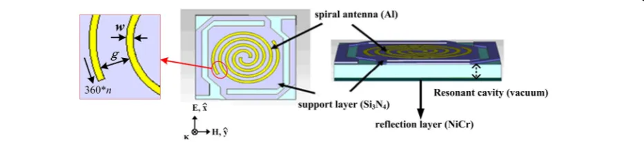
The 35-μm pitch pixel of THz microbolometer detector with a microbridge structure, shown in Fig. 1, was com-posed of diaphragm (sensitive area), cell contact, and two L-type legs which supported the diaphragm. This struc-ture had a long leg length and a large sensitive area. The diaphragm consisted of support layer, thermal sensitive layer (vanadium oxide), and THz absorption layer, with a reflection layer placed 2 μm away. The signal of the dia-phragm was transferred via the cell contact to readout
integrated circuit (ROIC) located under the reflection layer. Spiral antenna structure acting as the THz absorp-tion layer was integrated on the top of the support layer with a size of about 24 × 24μm. In our antenna-coupled microbridge structure, 0.1-μm nickel–chromium (NiCr) thin film acted as the reflection layer and 0.4-μm silicon nitride (Si3N4) film acted as the support layer. Spiral an-tenna structure was made of aluminum (Al) with a thick-ness of 0.1μm and an outside diameter of 20.8μm. The effects of structure parameters of spiral antenna on THz wave absorption of microbridge structure, including rota-tion angle (360*n), line width (w), and spacing (g) which are indicated in Fig. 1 with a partial enlarged drawing of the spiral antenna, were studied by changing different structure parameters.
Effect of Rotation Angle
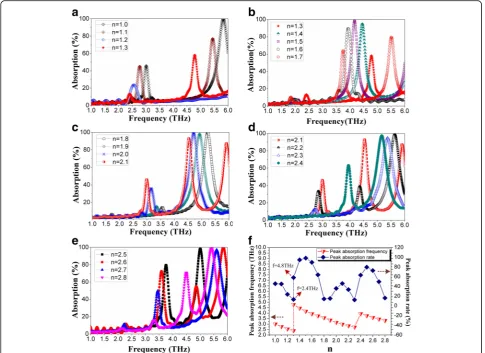
The effect of rotation angle of the spiral antenna was first studied by fixing the line width to 1μm and setting the ro-tation angle to 360*n(the rotation angle starting from the center of the spiral antenna, n changed in 1~2.8) in the simulation. The THz wave absorption curves of micro-bridge structures with different rotation angles of spiral antennas are shown in Fig. 2.
It can be seen from Fig. 2a that the peak absorption rate and the absorption frequency near 3 THz decrease with the increase of rotation angle whenn= 1.0~1.3. Figure 2b sug-gests that whenn= 1.3~1.7, there is a very weak absorption near 3 THz. The peak absorption frequency at higher fre-quency decreases with the increase of rotation angle. The peak absorption rate increases when n= 1.3~1.5 and then decreases when n= 1.5~1.7 due to increasing rotation angle. Figure 2c indicates that the peak absorption rate in-creases and the absorption frequency dein-creases near 3 THz with the increase of rotation angle when n= 1.8~2.1. Fig-ure 2d, e shows the THz wave absorption curves of micro-bridge structures with different rotation angles (360*n) when n= 2.1~2.4 and n= 2.5~2.8, respectively. It is clear that the effects of rotation angle on THz wave absorption when n= 2.1~2.3, n= 2.3~2.5, and n= 2.5~2.8 are similar to the effects whenn= 1~1.3,n= 1.3~1.5, and n= 1.5~1.8, respectively. This can also be concluded from Fig. 2f, which
[image:2.595.70.537.611.714.2]shows the variation of peak absorption rate and absorption frequency whennchanges in 1~2.8. It seems that the effect of rotation angle on THz wave absorption has a certain re-peatability betweenn= 1~2 andn= 2~3.
In addition to the repeatability, Fig. 2 also suggests that the absorption frequency keeps always decreasing with the increase of rotation angle. Whenn= 1.1 andn= 2.1, rela-tively high-peak absorption rate and low absorption fre-quency are obtained.
Effect of Line Width
THz wave absorptions of microbridge structures with dif-ferent line widths (w) of the spiral antennas were simu-lated when n= 1.1 (Fig. 3a–c) and n= 2.1(Fig. 3d), respectively. Figure 3a shows that the peak absorption rate and absorption frequency increase with the increase of line width in 0.3~1.3 μm. When the line width increases to 1.4~2.3 μm, the increase of peak absorption rate and absorption frequency slow down, as shown in Fig. 3b. When the line width changes in 2.4~2.8μm (Fig. 3c), the peak absorption rate and absorption frequency remain
essentially the same. Similar phenomenon can be observed in Fig. 3d when n= 2.1 andw= 0.3~1.7 μm, which indi-cates that the peak absorption rate and absorption fre-quency remain unchanged whenw is more than 1.3μm. This is conducive to the fabrication of spiral antenna-coupled microbridge structure for the slight deviation of line width in patterning will not lead to obvious change in THz wave absorption characteristics of the microbridge structure, which reduces the manufacturing difficulty and improves the process compatibility.
Compared to the spiral antenna with a rotation angle of 360*n (n= 2.1), the spiral antenna with a rotation angle of 360*n(n= 1.1) has an obvious advantage in that it provides higher peak absorption rate and lower ab-sorption frequency, besides, its simpler structure makes it easier to adjust the parameters of spiral antenna such as line width.
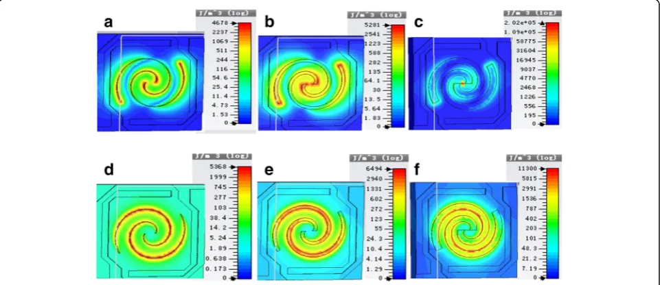
Figure 4 shows the energy density diagrams of electric field and magnetic field of spiral antenna-coupled micro-bridge structures when n= 1.1 with line widths of w= 0.3μm,w= 1.3μm, andw= 2.8μm, respectively.
Fig. 2THz wave absorption curves of microbridge structures with different rotation angles (360*n) of spiral antenna:an= 1.0~1.3;bn= 1.3~1.5;
[image:3.595.56.542.88.441.2]In the energy density diagrams of electric field and mag-netic field in Fig. 4, the change of color from blue to red in-dicates that the absorption rate of terahertz wave becomes larger. Energy of electric field and magnetic field absorbed by the antenna can be converted into heat energy. It can be seen from Fig. 4 that the absorption area of electric field en-ergy is mainly distributed in the center and both ends of
the spiral antenna, while the absorption area of magnetic field energy is mainly located in the position of antenna line. With the increase of line width, the absorption area of electric field energy moves toward the center and both ends and becomes more concentrated. The distribution of ab-sorption area of magnetic field energy becomes more uni-form due to the increase of line width.
Fig. 3THz wave absorption curves of microbridge structures with different rotation angles (360*n) and line widths (w) :an= 1.1,w= 0.3~1.3;b n= 1.1,w= 1.3~2.3;cn= 1.1,w= 2.3~2.8 ; anddn= 2.1,w= 0.3~1.5
Fig. 4Energy density diagrams of electric field and magnetic field of spiral antenna-coupled microbridge structures whenn= 1.1 with different line widths (w):aw= 0.3, electric field;bw= 1.3, electric field;cw= 2.8, electric field;dw= 0.3, magnetic field;ew= 1.3, magnetic field; andfw
[image:4.595.58.539.88.343.2] [image:4.595.58.539.485.693.2]Effect of Spacing
THz wave absorption curves of microbridge structures (n = 1.1, w= 2μm) with different spacing (spacing between adjacent lines,g= 0.65~2.5) are shown in Fig. 5. Figure 5 suggests that the peak absorption rate and absorption fre-quency increase with the increase of spacing from 0.65 to 2.5μm. The results in Fig. 5 show no linear variation of the peak absorption rate and absorption frequency with the increasing of spacing. As the spacing increases, the in-crease of peak absorption rate and absorption frequency becomes slower.
As we have discussed before, the increase of peak absorp-tion rate and absorpabsorp-tion frequency slows down with the in-crease of line width and remains unchanged when the line width is bigger than a certain value. Now, it becomes clear that, this effect is not only attributed to the change of line width, the increase of line width will lead to the decrease of spacing in the case of constant outside diameter of spiral antenna. The peak absorption rate and absorption fre-quency increase with the increase of line width, while it has opposite change trend with the increase of spacing.
The effects of different structure parameters of spiral antenna on THz wave absorption of microbridge struc-ture have been discussed by the simulation before. Some
interested results are obtained. However, the absorption rate and absorption frequency have not reached the ideal value for the target frequency of 2.52 THz, and it seems difficult to achieve due to the size of spiral antenna lim-ited by the size of the support layer.
Spiral Antenna with Extended Legs
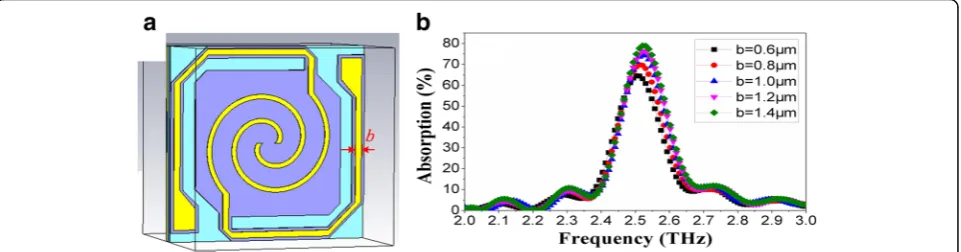
Aimed at the limitation of the size of the support layer, a novel spiral antenna-coupled microbridge structure was proposed by making full use of the structure characteris-tics of the microbolometer. As shown in Fig 6a, the spiral antenna is extended to the bridge legs to increase the ef-fective area of the antenna.
THz wave absorption curves of spiral antenna-coupled microbridge structures (n= 1.1,w= 1μm) with different leg widths (b= 0.6~1.4) are shown in Fig. 6b. Figure 6b indicates that the absorption frequency is decreased to near 2.52 THz and the peak absorption rate is improved obviously due to the contribution of the extended legs. The peak absorption rate and absorption frequency in-crease with the inin-crease of leg width.
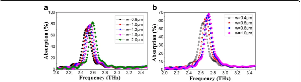
THz wave absorptions of microbridge structures with different line width (w) of the spiral antenna with a leg width of 1μm were simulated whenn= 1.1 (Fig. 7a) and
n= 2.1(Fig. 7b), respectively. Since the outside diameters of spiral antenna structures were limited by the size of the support layer (about 24 × 24μm) and spiral antenna with a greater rotation angle permits a smaller line width in the case of the same outside diameter (20.8 μm), the line widths (w) of the spiral antennas with different rotation angle (360*n) were set to 0.8~2.0 and 0.4~1.0μm whenn = 1.1 and n= 2.1, respectively. Figure 7 shows that the peak absorption rate and absorption frequency increase with the increase of line width both whenn= 1.1 andn= 2.1. It becomes clear that the extending of spiral antenna contributes to the decrease of absorption frequency. It can be seen that peak absorption of spiral antenna-coupled microbridge structure occurs at 2.52 THz when n= 1.1 with a line width of 1μm and a leg width of 1μm, and an absorption rate of more than 75% is achieved. Figure 7b
Fig. 5THz wave absorption curves of microbridge structures with different spacing (g)
[image:5.595.56.292.88.235.2] [image:5.595.59.540.587.713.2]suggests that the absorption frequency can hardly be opti-mized to near 2.52 THz when n= 2.1 for a line width smaller than 0.4μm will be required, which results in diffi-culty in manufacturing.
Figure 8 shows the energy density diagrams of elec-tric field and magnetic field of spiral antenna-coupled microbridge structures when n= 1.1 with a line width of 1 μm and a leg width of 1 μm. It can be seen that THz wave is absorbed by both spiral antenna and the legs, while spiral antenna on the support layer makes greater contribution, which is advantageous to temperature rise of the diaphragm with thermal sensi-tive film.
The design of novel spiral antenna with extended legs is a good solution for high absorption rate at low ab-sorption frequency of 2.52 THz. At the same time, the spiral antenna is extended to the positions of cell con-tacts through the bridge legs. This design makes it pos-sible to use the spiral antenna as electrode lead simultaneously to connect the thermal sensitive film to readout circuit, which is very beneficial to integration and process simplification. This provides an effective way which is easy to accomplish and compatible with the manufacturing process of THz microbolometer focal-plane array to enhance THz absorption and im-prove detection performance.
Conclusions
In this paper, we have presented the design and electromag-netic simulation of antenna-coupled bolometer that works in THz band. Starting with infrared microbolometer tech-nology, spiral antenna-coupled microbridge structures were developed in this paper. Novel spiral antenna with extended legs was first designed based on the structure characteris-tics of microbolometer. Results of the structure design and electromagnetic simulation were presented, concentrating on the spectral absorption. The influences of different structure parameters of the spiral antenna on THz wave ab-sorption were discussed. The extended legs of spiral an-tenna, which contributed to the increase of THz wave absorption rate and the decrease of absorption frequency, made it possible to use the spiral antenna as electrode lead simultaneously for process simplification. A spiral antenna-coupled microbridge structure with optimized absorption at 2.52 THz was obtained, aiming at applications in detec-tion and imaging. This research was only the first step in demonstrating the feasibility of antenna-coupled THz bol-ometer detectors by proposing novel spiral antenna-coupled microbridge structures and demonstrating its im-provements on THz absorption and manufacturing process. However, it established a foundation for fabrication of THz microbolometer and its applications in sensing and imaging which will be done in further work.
Fig. 7THz wave absorption curves of microbridge structures with a leg width of 1μm whenn= 1.1(a) andn= 2.1 (b) with different line widths (w)
[image:6.595.58.540.88.220.2] [image:6.595.57.539.579.702.2]Methods
[image:7.595.306.536.124.734.2]To explain the nature of the frequency tuning by spiral antennas, finite element simulations were car-ried out using commercial software Microwave Stu-dios by CST. We simulated a single unit cell of antenna-coupled microbridge structure as shown in Fig. 1. The Al regions were simulated as lossy metal with a conductivity of σAl= 3.56 × 10⁷S/m, and the reflection layer was modeled as lossy NiCr with
σNiCr= 1 × 10⁷S/m. The Si3N4 layer supporting the antenna was modeled as a dielectric with εSi3N4¼1 and σSi3N4 ¼0S=m , and the resonant cavity under-lying the diaphragm was modeled with εvacuum= 1 and σvacuum= 0S/m. In simulations, we used adaptive
mesh refinement to ensure an accurate numerical solution with a short simulation time. The final mesh typically contained about 93,000 hexahedrons, and the minimum edge length was about 0.15 μm. We investigated the S-parameters of transmission
~
S21
and reflection S~11
of a single unit cell with perfect electric (PE) and perfect magnetic (PM) boundary conditions along the ^x and ŷ directions, respectively. The absorptivity was calculated using the equation A= 1−|S21|2−|S11|2.
Abbreviations
IR:Infrared; NiCr: Nickel–chromium; PE: Perfect electric; PM: Perfect magnetic; RIE: Reactive-ion etching; ROIC: Readout integrated circuit; Si3N4: Silicon
nitride; THz: Terahertz
Acknowledgements
The authors acknowledge the assistance of the staff at the State Key Laboratory of Electronic Thin Films and Integrated Devices in the University of Electronic Science and Technology of China
Funding
This study was supported by the National Natural Science Foundation of China (NSFC) (No. 61501092), National Science Funds for Creative Research Groups of China (No. 61421002), Fundamental Research Funds for the Central Universities (No. ZYGX2015KYQD016), and Open Foundation of Key Laboratory of Photoelectric Detection and Sensor Integration Technology of the Ministry of Education (Grant No. KFJJ201502).
Authors’Contributions
JG and TZ performed the design, analyzed the data, and drafted the manuscript. JW and YJ guided the idea and the simulations and checked the figures. All authors read and approved the final manuscript.
Competing Interests
The authors declare that they have no competing interests.
Author details
1State Key Laboratory of Electronic Thin Films and Integrated Devices, University of Electronic Science and Technology of China, Chengdu 610054, China.2School of Optoelectronic Information, University of Electronic Science and Technology of China, Chengdu 610054, China.
Received: 17 November 2016 Accepted: 17 January 2017
References
1. Federici JF, Schulkin B, Huang F, Gary D, Barat R, Oliveira F, Zimdars D (2005) THz imaging and sensing for security applications—explosives, weapons and drugs. Semicond Sci Technol 20(7):S266–S280
2. Kawase K (2004) Terahertz imaging for drug detection and large-scale integrated circuit inspection. Opt Photonics News 15(10):34–39
3. Nguyen DT, Simoens F, Ouvrier-Buffet JL, Meilhan J, Coutaz JL (2012) Broadband THz uncooled antenna-coupled microbolometer array—electromagnetic design, simulations and measurements. IEEE Trans Terahertz Sci Technol 2(3):299–305 4. Crowe TW (1989) GaAs Schottky barrier mixer diodes for the frequency
range 1–10 THz. Int J Infrared and Millim Waves 10(7):765–777 5. Knap W, Deng Y, Rumyantsev S, Shur MS (2002) Resonant detection of
subterahertz and terahertz radiation by plasma waves in submicron field-effect transistors. Appl Phys Lett 81(24):4637–4639
6. Helisto P, Luukanen A, Gronberg L, Penttila JS, Seppa H, Sipola H, Dietlein CR, Crossman EN (2006) Antenna-coupled microbolometers for passive THz direct detection imaging arrays, Proceedings of the 1st European Microwave Integrated Circuits Conference., pp 35–38
7. Su B, Zhang C, Duan G (2010) A detection technology of THz based on surface plasmon resonance, Proc SPIE 7854: 78541H_1–78541H_9 8. Choi B, Dou X, Fang Y, Phillips BM, Jiang P (2016) Outstanding surface
plasmon resonance performance enabled by templated oxide gratings. Phys Chem Chem Phys 18(37):26078–26087
9. Fang Y, Phillips BM, Askar K, Choi B, Jiang P, Jiang B (2013) Scalable bottom-up fabrication of colloidal photonic crystals and periodic plasmonic nanostructures. J Mater Chem C 1(38):6031–6047
10. Lee AWM, Williams BS, Hu Q, Reno JL (2006) Real-time imaging using a 4.3-THz quantum cascade laser and a 320 × 240 microbolometer focal-plane array. IEEE Photon Technol Lett 18(13):1415–1417
11. Lee AWM, Hu Q (2005) Real-time, continuous-wave terahertz imaging by use of a microbolometer focal-plane array. Opt Lett 30(19):2563–2565 12. Behnken BN, Karunasiri G, Chamberlin DR, Robrish PR, Faist J (2008)
Real-time imaging using a 2.8 THz quantum cascade laser and uncooled infrared micrometer camera. Opt Lett 33(5):440–442
13. Kruse P, Dodson R, Anderson S, Kantor L, Knipfer M, McManus T, Wood A, Rezachek T (1998) Infrared imager employing a 160 × 120 pixel uncooled bolometer array. Proc SPIE 3436:572–577
14. Murphy DF, Ray M, Wyles R, Asbrock JF, Lum NA, Wyles J, Hewitt C, Kennedy A, Van Lue D, Anderson JS, Bradley D, Chin R, Kostrzewa T (2003) High sensitivity 25μm microbolometer FPAs. Proc of SPIE 4820:208–219 15. Backer BS, Butler NR, Kohin M, Gurnee MN, Whitwam JT, Breen T (2002)
Recent improvements and developments in uncooled systems at BAE SYSTEMS North America. Proc SPIE 4721:83–90
16. Li C, Skidmore GD, Howard C, Han CJ, Wood L, Peysha D, Williams E, Trujillo C, Emmett J, Robas G, Jardine D, Wan C-F, Clarke E (2007) Recent development of ultra small pixel uncooled focal plane arrays at DRS, Proc SPIE 6542: 65421Y_1–65421Y_12
17. Oda N, Yoneyama H, Sasaki T, Sano M, Kurashina S, Hosako I, Sekine N, Sudoh T, Irie T (2008) Detection of terahertz radiation from quantum cascade laser using vanadium oxide microbolometer focal plane arrays, Proc SPIE 6940: 69402Y_1–69402Y_12
18. Kearney B, Alves F, Grbovic D, Karunasiri G (2012) Tunable THz absorption using Al/SiOx planar periodic structures, Proc SPIE 8363: 836309_1–836309_6
19. Hosako I, Sekine N, Oda N, Sano M, Kurashina S, Miyoshi M, Sonoda K, Yoneyama H, Sasaki T (2011) A real-time terahertz imaging system consisting of terahertz quantum cascade laser and uncooled microbolometer array detector, Proc SPIE 8023: 80230A_1–80230A_6 20. Maier T, Bruckl H (2009) Wavelength-tunable microbolometers with
metamaterial absorbers. Opt Lett 34(19):3012–3014
21. Gou J, Wang J, Zheng X, Gu D, Yu H, Jiang Y (2015) Detection of terahertz radiation from 2.52 THz CO2 laser using a 320 × 240 vanadium oxide microbolometer focal plane array. RSC Advances 5:84252–84256 22. Wyss RA, Neto A, McGrath WR, Bumble B, LeDuc H (2000)
Submillimeter-wave spectral response of twin-slot antennas coupled to hot electron bolometers, Proc 11th Int Space Terahertz Technol Symp., pp 379–388 23. Morf T, Klein B, Despont M, Drechsler U, Kull L, Corcos D, Elad D, Kaminski
24. Singh R, Rockstuhl C, Menzel C, Meyrath TP, He M, Giessen H, Lederer F, Zhang W (2009) Spiral-type terahertz antennas and the manifestation of the Mushiake principle. Opt Express 17:9971–9980
25. Son LN, Tachiki T, Uchida T (2013) Fabrication and evaluation of thin-film spiral-antenna-coupled VOxmicrobolometer by metal–organic decomposition. Jpn J
Appl Phys 52:046601_1–046601_4
26. Meilhan J, Dupont B, Goudon V, Lasfargues G, Dera JL, Nguyen DT, Ouvrier-Buffet JL, Pocas S, Maillou T, Cathabard O, Barbieri S, Simoens F (2011) Active THz imaging and explosive detection with uncooled antenna-coupled microbolometer arrays, Proc SPIE 8023: 80230E_1–80230E_13 27 Oden J, Meilhan J, Lalanne-Dera J, Roux JF, Garet F, Coutaz JL, Simoens F
(2013) Imaging of broadband terahertz beams using an array of antenna-coupled microbolometers operating at room temperature. Opt Express 21(4):4817–4825
28 Cherednichenko S, Hammar A, Bevilacqua S, Drakinskiy V, Stake J, Kalabukhov A (2011) A room temperature bolometer for terahertz coherent and incoherent detection. IEEE Trans THz Sci Technol 1(2):395–402
29 Markish O, Leviatan Y (2016) Analysis and optimization of terahertz bolometer antennas. IEEE Trans Antennas Propag 64(8):3302–3309
Submit your manuscript to a
journal and benefi t from:
7Convenient online submission
7Rigorous peer review
7Immediate publication on acceptance
7Open access: articles freely available online 7High visibility within the fi eld
7Retaining the copyright to your article