© 2016, IRJET | Impact Factor value: 4.45 | ISO 9001:2008 Certified Journal | Page 2679
A MULTILEVEL INVERTER FOR PV SYSTEM USING ADAPTIVE MPPT
CONTROL WITH REDUCED HARMONICS
K.Princy
1, M.Shyamala Gowri
21
PG Student, Dept. of EEE, Erode Sengunthar Engineering college, Tamilnadu, India
2Assistant Professor, Dept. of EEE, Erode Sengunthar Engineering College, Tamilnadu, India
---***---Abstract -
Multilevel inverter technology has emergedrecently as a very important alternative in the area of high-power medium voltage energy control. This paper proposes a concept based on the combination of Maximum Power Point Tracking (MPPT) and Cascade H-bridge inverter. In existing system it requires separate dc source of each level, there is no voltage stability in output in open loop system .In open loop if input had fluctuation output voltage varies so ripple will high Increased output harmonic content. In proposed system by Implement closed loop fuzzy algorithm with interleaved converter so output voltage is very stable and ripple reduction. If input voltage had fluctuation also output voltage will constant. Fuzzy is new method in optimization technique so response time is very lower than other technique and also implementing speed control in induction motor. Additional advantage is, if one of the H-bridges fail, the inverter can still be operated at full load with reduced number of levels. The paper presents a PV fed five level Multi Level Inverter (MLI) wherein the Maximum Power Point Tracking (MPPT) is done using an Artificial Neural Network (ANN). PV panel modeling, ANN based MPPT algorithm, DC-DC Buck Boost Converter and the Five level MLI are simulated in MATLAB/SIMULINK.
Key Words: Cascaded H-bridge, Multilevel Inverter, 15-level inverter. Maximum Power Point Tracking (MPPT), Photovoltaic (PV),Pulse Width Modulation(PWM)
1.INTRODUCTION
The multilevel inverter was introduced as a solution to increase the converter operating voltage above the voltage limits of classical semiconductors. One of the significant advantages of multilevel configuration is the harmonic reduction in the output waveform without increasing switching frequency or decreasing the inverter power output. The output voltage waveform of a multilevel inverter is composed of the number of levels of voltages, typically obtained from capacitor voltage sources. The multilevel starts from a level of three and as the number of levels reach infinity, the output THD (Total Harmonic Distortion) approaches zero. The number of the achievable voltage levels, however, is limited by voltage unbalance problems, voltage clamping requirement, circuit layout, and packaging constraints. Multilevel inverters synthesizing a large number of levels have a lot of merits such as improved output
waveform, a smaller filter size, a lower EMI (Electro Magnetic Interference), and other advantages. The principle advantage of using multilevel inverters is the low harmonic distortion obtained due to the multiple voltage levels at the output and reduced stresses on the switching devices used. Numerous industrial application have begun to require higher power apparatus in recent years a multilevel power converters structure has been introduced as an alternative in high power and medium voltage situations. A multilevel converter not only achieves high power ratings, but also enables the use of renewable energy sources such as photovoltaic, wind and fuel cells can be easily interfaced to a multilevel converter system for a high power application. The concept of multilevel converter system has been introduced since 1975. The term multilevel began with the three level convertor. Subsequently, several multilevel converter topologies have been developed.
In recent days the research on multilevel inverters has been widely increasing due to its capability of high power medium voltage application. In low level inverters the harmonic content of output current can be reduced by increasing the switching frequency. But the switching frequency is restricted by switching loss in high power and high voltage applications. In such applications multilevel inverter has been used.
2.OPERATING PRINCIPLE
The multilevel inverter is an arrangement of a 3L-ANPC converter and an H-bridge connected as shown in fig.1 the two DC link capacitors C1 and C2 provides the midpoint required for for the 3L-ANPC converter.The converter has twenty four switching states ,the switching states generates seven different voltage levels 3VdC, 2VdC, VdC,0, VdC, -2VdC, - 3VdC.
The switching states are the combination of six switching states provided by the 3L-ANPC converter and the four switching states of the H-bridge submodule.
The voltage across the capacitor of the H-bridge submodule is affected when it is connected to the output terminal and one of the dc-link terminals, when
the output phase
voltage (VrO) is equal to Vdc and 3Vdc
.
© 2016, IRJET | Impact Factor value: 4.45 | ISO 9001:2008 Certified Journal | Page 2680 contents in the ouput load current and voltage wafeforms.
SVPWM also improves the total harmonic distortion (THD)
2.1 SPACE VECTOR PWM
The Space vector pwm method is an attractive alternative to the classic multilevel pulse width modulation techniques considering the following aspects, mainly, minimization of voltage and current total harmonic distortion (THD), extension of range of linear operation; and least number of commutations. To solve the problem of computational complexity in multilevel inverters due to the large number of space vectors and redundant switching states, a simple and general space vector PWM algorithm is proposed. Based on this algorithm, the location of the reference voltage vector can be easily determined and the calculation of dwell times becomes very simple. It is also mentioned that this method requires lower memory spaces there is no need of any look-up table.
[image:2.595.366.500.132.239.2]Figure 1.Voltage vectors of 3,5 and 7-level voltage
source
The typical seven-level multilevel inverter is shown in Fig. 3.1 , where a separate dc power supply is used for each Bridge. Its corresponding space voltage vector diagram is illustrated in Fig. , in which the vectors for the 3, 5, and 7- level inverters are also illustrated. For the 7-level inverter, there are 216 small triangles and the vertex of each triangle represents a space vector.
The hexagonal vectors can be divided into six major triangular sectors (I to VI). Only the first sector of the coordinate is used because the vectors located in the other sectors can be transformed to first sector by clockwise rotating by an angle of k*(pi/3) k = (1,2,3,4,5 for sector 2 to 6). As all the sectors are identical and Vref decomposed into m and n axis it is easy to obtain the m and n axis component of Vref as Vrm and Vrn as given next:
Vrm= (2*M *Vref / 3Vdc) sin (p/ 3- q) (1) Vrn= (2*M *Vref / 3Vdc) sin(q) (2)
Where θ is speed of rotating reference vector.
The proposed algorithm considers over-modulation case also. It is easy to judge whether SVPWM is in overmodulation
region or not, simply by checking the following inequality:if (Vrm + Vrn) > M, it becomes over-modulation.
[image:2.595.84.259.336.458.2]
Fig. 2 switching vectors
All possible switching vectors for a three-leg inverter using space vector modulation is shown. An example Vref is shown in the first sector. Vref_MAX is the maximum amplitude of Vref before non-linear overmodulation is reached.
More complicated SVM strategies for the unbalanced operation of four-leg three-phase inverters do exist. In these strategies the switching vectors define a 3D shape (a hexagonal prism in coordinates or adodecahedron in abc Three-Dimensional Space Vector Modulation in abc coordinates rather than a 2D hexagon
2.2 MAXIMUM POWER POINT ALGORITHM
Z
Fig.3 Centralized MPPT algorithm of multiple
local PV modules.
[image:2.595.309.559.396.668.2]© 2016, IRJET | Impact Factor value: 4.45 | ISO 9001:2008 Certified Journal | Page 2681 For example, one previous report has suggested an MPPT
sequence in which the next module’s reference begins tracking the MPP after the previous other module has completed its tracking routine . Therefore, if the PV-voltage settling time at a step of the reference update takes Ts, then the next module should wait for the number of MPP-tracking steps in multiple times of Ts, which makes the tracking speed very slow. On the other hand, the proposed controller distributes the updated references to each module in turn, without waiting for the settling time. For example, a module can update the PV reference during the settling response of the previous other module since the modules do not need to wait for the previous module’s MPP arrival. Therefore, this method can provide high-MPP tracking speeds, unlike the previous multimodal.MPPT method. Consequently, the MPPT efficiencyof the proposed is almost the same as that of the individual MPPT controller. This is because the PV transient response is quite slow compared to the DSP and communication speed.
3.DESCRIPTION
3.1 OVERVIEW
As the demand for the power increases, the dc source to the multilevel inverter is provided by the PV panel. The pv panel produces continuous ripple free input to the cascaded inverter. MPPT techniques are used in order to obtain maximum power. Also the produced power by the panel is improved using the boost converters connected with the pv panel. Irjet Template sample paragraph .Define abbreviations and acronyms the first time they are used in the text, even after they have been defined in the abstract. Abbreviations such as IEEE, SI, MKS, CGS, sc, dc, and rms do not have to be defined. Do not use abbreviations in the title or heads unless they are unavoidable.
Fig.4 Block diagram for developed
3.2 PV PANEL
A solar panel is a set of solar photovoltaic modules electrically connected and mounted on a supporting structure. A photovoltaic module is a packaged, connected assembly of solar cells. The solar module can be used as a component of a larger photovoltaic system to generate and supply electricity in commercial and residential applications. Each module is rated by its DC output power under standard test conditions (STC), and typically ranges from 100 to 320 watts.
The efficiency of a module determines the area of a module given the same rated output - an 8% efficient 230 watt module will have twice the area of a 16% efficient 230 watt module. A single solar module can produce only a limited amount of power; most installations contain multiple modules. A photovoltaic system typically includes a panel or an array of solar modules, an inverter, and sometimes abattery and or solar tracker and interconnection wiring.
3.3 BOOST CONVERTER
DC-DC converters can be used as switching mode regulators to convert an unregulated dc voltage to a regulated dc output voltage. The regulation is normally achieved by PWM at a fixed frequency and the switching device is generally BJT, MOSFET or IGBT. The minimum oscillator frequency should be about 100 times longer than the transistor switching time to maximize efficiency. This limitation is due to the switching loss in the transistor. The transistor switching loss increases with the switching frequency and thereby, the efficiency decreases. The core loss of the inductors limits the high frequency operation. Control voltage Vc is obtained by comparing the output voltage with its desired value. Then the output voltage can be compared with its desired value to obtain the contol voltage Vcr. The PWM control signal for the dc converter is generated by comparing Vcr with a sawtooth voltage Vr.[8]. There are four topologies for the switching regulators: buck converter, boost converter, buck-boost converter, cứk converter. However the boost converter is used in this project for improving the voltage gain of power obtained from the panel.
3.4 MULTILEVEL INVERTER
© 2016, IRJET | Impact Factor value: 4.45 | ISO 9001:2008 Certified Journal | Page 2682 Types of multilevel Inverters:
Mostly there are three kinds of multilevel inverter. 1.Diode clamped inverter
2.Flying capacitor inverter 3.Cascaded multilevel inverter.
CASCADED MULTILEVEL INVERTER
Cascaded multilevel inverter is also called as Multicell Inverter. The cascaded inverter is made up from series connected single phase full bridge inverters .Each H-bridge has its own isolated DC source. Each separated DC sources is connected to H-bridge inverter and can produce voltages of 0, +Vdc and -Vdc, where Vdc is the voltage of its DC bus. Each inverter generates quasi-squared voltage waveforms with various duty cycles. To synthesize a multilevel waveform, the ac outputs of each different level H-bridge cells are connected in series. The synthesized voltage waveform is, therefore, the sum of the inverter outputs i.e. v = v1+v2+....+vm. The number of output phase voltage levels in a cascade multilevel inverter is then 2s+1, where s is the number of isolated dc sources in a cascaded multilevel inverter. The staircase output voltage waveform of 2s+1 levels inverter.
For real power conversions from ac to dc and then dc to ac, the cascaded inverters need separate dc sources. The structure of separate dc sources is well suited for various renewable energy sources such as fuel cell, photovoltaic, and biomass. Connecting dc sources between two converters in aback to back fashion is not possible because a short circuit can be introduced when two back to back converters are not switching synchronously. The number of possible output voltage levels is more than twice the number of dc sources (m=2s+1). The series of H-bridge makes for modularized layout and packaging. This will enable the manufacturing process to be done more quickly and cheaply.
[image:4.595.41.258.549.749.2]Fig 5 Single phase cascaded m+1 level inverter
Table 1: Cascaded five level inverter voltage and
corresponding switching states.
3.5 CIRCUIT DESCRIPTION
It has a dc link voltage of 80V. The flying capacitors and DC link capacitors are designed with values1000 and 3300 micro farads respectively. The multilevel converter based on the cascaded interconnection of a 3L-ANPC converter and individual H-bridges for each phase.the output of the inverter is around 90V and is given as an input to the asynchronous machine. The value of the inverter current and voltages are measured. The performance of the motor such as speed, torque and the rotor currents are noted.
A solar panel is a set of solar photovoltaic modules electrically connected and mounted on a supporting structure. A photovoltaic module is a packaged, connected assembly of solar cells. A Solar Cell is a device that converts light into electric current using the photoelectric-effect. The photovoltaic panel is connected with six boost converters. The boost converter helps to improve the voltage gain of the energy observed by the pv panel.
© 2016, IRJET | Impact Factor value: 4.45 | ISO 9001:2008 Certified Journal | Page 2683
Fig.6: Circuit diagram for developed system
4.SIMULATION RESULTS
The proposed system was simulated using Simulink of mat lab Toolbox. Different tests were carried out, considering the inverter operations.
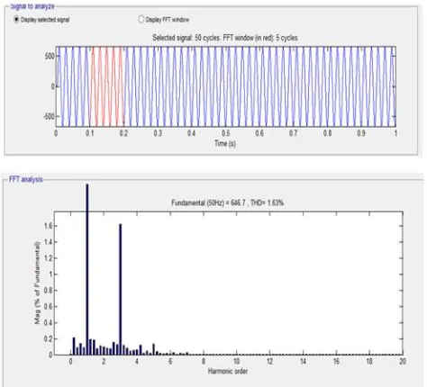
[image:5.595.51.231.117.330.2]4.1HARMONIC ELIMINATION WITH FFT ANALYSIS:
Fig.7 Harmonic elimination of FFT analysis
In this part there have been done some simulations in order to compare the different balancing strategies. In all the simulations the amplitude has been 1000 amps for all of the phase currents. In the switching frequency was set to be
1000 Hz, while in this report it will be 1050 Hz. The order of harmonics is eliminated by MPPT controller. The name of fast Fourier transform analysis can useful to show the variation of eliminating harmonic order in inverter circuit.
[image:5.595.318.552.194.447.2]4.2 LOAD VOLTAGE & CURRENT:
Fig.8 output current and load voltage
The PV system consisting of the dc injection in the primary side voltage. That process can connect with load voltage and the inverter side connects with the output. With the help of MPPT controller the output efficiency is high.
4.3 OUTPUT WAVWFORM OF VOLTAGE AND
CURRENT
[image:5.595.44.281.475.690.2]
© 2016, IRJET | Impact Factor value: 4.45 | ISO 9001:2008 Certified Journal | Page 2684 The waveform consist of voltage and current,here fifteen
level output is showen sine wave is formed and it will reduce the harmonics in the output side.
5.CONCLUSION
The space vector technique method has been studied. This method has the advantage of improving the total harmonic distortion over other PWM methods. Also this technique features easy implementation and more importantly, minimum harmonic content in the inverter output voltage and current of the Induction Motor Load.
The simulation of the multilevel converter circuits is completed. The seven level inverter uses the cascaded interconnection of a 3L-ANPC converter and individual H-bridges for each phase with SVPWM is proposed. The simulation with multilevel converter with induction motor has been done and the output is verified.
REFERENCES
[1] S. R. Pulikanti, G. S. Konstantinou, and V. G. Agelidis, “Hybrid Seven-Level Cascaded Active Neutral-Point-Clamped-Based Multilevel Converter Under SHE-PWM ,” IEEE ,Trans. Ind. Electron., vol. 60, no. 11, Oct. 2013. [2] S. Kouro, M. Malinowski, K. Gopakumar, J. Pou, L. G. Franquelo, B.Wu, J. Rodriguez, M. A. Perez, and J. I. Leon, “Recent advances and industr ial applications of multilevel converters,” IEEE Trans. Ind. Electron., vol. 57, no. 8, pp. 2553–2580, Aug. 2010.
[3]M. Veenstra and A. Rufer, “Control of a hybrid a symmetric multilevel inverter for competitive medium-voltage industrial drives,” IEEE Trans. Ind. Appl., vol. 41, no. 2, pp. 655–664, Mar./Apr. 2005.
[4]T. B. Soeiro and J. W. Kolar, “The new high effi ciency hybrid neutralpoint- clamped converter,”IEEE Trans. Ind. Electron., vol. 60, no. 5, pp. 1919–1935, May 2013.
[5]Z. Du, B. Ozpineci, L. M. Tolbert, and J. N. Chiasson, “DC–AC cascaded H-bridge multilevel boost inverter with no inductors for electric/hybrid electric vehicle applications,” IEEE Trans. Ind. Appl., vol. 45, no. 3, pp. 963–970, May/Jun. 2009.