© 2016, IRJET | Impact Factor value: 4.45 | ISO 9001:2008 Certified Journal
| Page 1423
Design and Shape Optimization of Excavator Bucket
Sujit Lomate
1, Siddaram Biradar
2, Ketan Dhumal
3Amol Waychal
41
Sujit Lomate, Dept. Design Engineering DPCOE pune ,Maharashtra ,India
2
Professor Siddaram Biradar,Dept.Design Engineering DPCOE Pune, Maharashtra India
3Professor Ketan Dhumal Dept.Design Engineering DPCOE Pune ,
4
Professor Amol Wayachal Dept.Design Engineering Siddhant college of engineering
---***---Abstract -
Rapidly growing rate of industry of earthmoving machines is assured through the high performance construction machineries with complex mechanism and automation of construction activity.An excavator is a typical hydraulic heavy-duty human operated machine used in general versatile construction operations, such as digging, ground levelling, carrying loads, dumping loads and straight traction.In this design of bucket is critical task in context of digging force developed through actuators during the digging operation. This paper focuses on the evaluation method of bucket capacity and digging forces required to dig the terrain for light duty and heavy duty construction work. This method provides the prediction of digging forces and can be applied for autonomous operation of excavation task. The evaluated digging forces can be used as boundary condition and loading conditions to carry out Finite Element Analysis of the Excavator mechanism for strength and stress analysis. An analytical approach provided for static force analysis of mini hydraulic excavator attachment. The objective of this paper is to design an excavator bucket to get smooth flow of material and to get effective digging forces.
Key Words: Excavator, optimization, bucket volume calculation, stress analysis.
1. INTRODUCTION
Applications for excavator in India include use as a utility machine at large construction sites (roads and dams for example) and urban infrastructure projects as well as the loading of hoppers and trucks, trenching, the cleaning of canals and ditches, general excavation, solid waste management and even demolition and mining work. An excavator is an engineering vehicle consisting of a bucket with cabin for the operator and tracked system for movement and engine is used for power generation. Hydraulic system is used for operation of the machine while digging or moving the material. Excavation is of
prime importance in mining, earth removal and general earthworks. Hydraulic cylinders apply forces to boom, arm and the bucket to actuate the mechanism. Depending on the mechanism position, working pressure and diameter of the hydraulic cylinders, the amount of excavation force changes. In practice, boom cylinders are used for adjusting the bucket position not for digging. They may be used for lifting purpose. While arm and bucket cylinder is used for excavation. Thus, calculation of digging force must be carried out separately when arm or bucket cylinder is the active cylinder [2]. The maximum digging forces are the digging forces that can be exerted at the outermost cutting point. These forces are calculated by applying working circuit pressure to the cylinder(s) providing the digging force without exceeding holding circuit pressure in any other.As the use of excavator in day to day life is increasing for many purposes but the applicable site is not inspected properly due urgency of work by the owner or the contractor due to which improper handling of it leads to damage of the ground engaging tool i.e. bucket. The bucket of the excavator is main contacting part of it which comes in contact with the soil and rocks while doing excavation at various sites. So in this case sometimes the bucket gets damage due to some improper handling by the operators, which leads to the damage .Here I calculate the stresses in bucket by analytically and Finite analysis approach and then compares their results. Here needs to modify bucket shape for smooth flow of material and to improve machine performance.
2.LITERATURE REVIEW
© 2016, IRJET | Impact Factor value: 4.45 | ISO 9001:2008 Certified Journal
| Page 1424
Design and Analysis of an Excavator Bucket. Manisha P.Tupkaret al .(2) The objective of this paper is to design an excavator bucket by using CREO-parametric 2.0 software. Model is exported through IGES file format for meshing in analysis software Boundary conditions and the forces are applied at the tip of teeth of excavator bucket. Static analysis is done in ANSYS 13.0 analysis software. In this paper the stresses developed at the tip of excavator bucket teeth are calculated. Percentage error between stress Analytical result and stress ANSYS result are calculated.
Catalogs JCB India ltd (3) Analysis methods ,loading conditions, attachment dimensions ,material standards, cylinder pressure, boom arm and link dimensions and all other standard.
3. PROBLEM FORMULATION
In the era of globalization and tough competition, the use of machines is increasing for the earth moving works considerable attention has been focused on designing of the earth moving equipment’s. Thus, it is very much necessary for the designers to provide not only a equipment of maximum reliability but also of minimum weight and cost, keeping design safe under all loading conditions [2]. Although excavation is ubiquitous in the construction industry, most day-to-day operations proceed on technology that is decades old— technology that has not kept pace with other industries. A recent trend towards greater automation of excavation machines reflects a larger movement in the construction industry to improve efficiency. Currently, human operators require ten to fifteen years of experience before they can be considered experts. Their work is often dirty, strenuous and repetitive [5]. Autonomous excavation has attracted interest because of the potential for increased productivity and lower labour costs. This research concerns the problem of automating a hydraulic excavator for mass excavation, where tons of earth are excavated and loaded into trucks. This application is commonly found in many constructions and mining scenarios. In such applications, fast operational speed of these machines is desired, because it directly translates to increased productivity.
4. METHODOLOGY-
Chart -1 Flow chart
5. BUCKET DESIGN
© 2016, IRJET | Impact Factor value: 4.45 | ISO 9001:2008 Certified Journal
| Page 1425
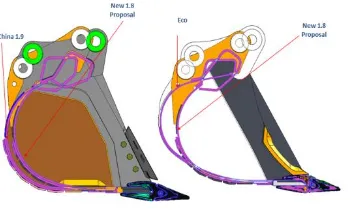
Fig. 1 Bucket shape optimization5.1. Bucket capacity calculations-
Bucket capacity is a measure of the maximum volume of the material that can be accommodated inside the bucket of the backhoe excavator. Bucket capacity can be either measured in struck capacity or heaped capacity. Globally two standards used to determine the heaped capacity, are: (i) SAE J296: “Mini excavator and backhoe bucket volumetric rating”, an American standard (ii) CECE (Committee of European Construction Equipment) section VI, a European standard [2]. The struck capacity directly measured from the 3D model of the backhoe bucket excavator for our case as shown in Fig.1 by following the SAE J296 standards [2]. As can be seen from the left side of the Fig. 1, P Area is the area bounded by struck plane (blue line) and side protector (red curve),
Struck volume, Vs-The struck volume is calculated as follows.
When the ratio X/Y less than or equal to12, the strike surface is used. This provides a reduction of the struck volume so as to
take the indentation into account. Then
Top volume, Vt- The Y indentation shall not be taken into consideration for the calculation. The W4 dimension shall be included for the calculation.The top volume is calculated as follows (see Figure 11).
Grab-type bucket -Struck volume, Vs-The struck volume is calculated as follows
Top volume,Vt- If the operating mechanism of the grab-type bucket is included in the top volume (Vt), the top volume shall be decreased by the volume of the mechanism (Vm)
Expression of volumetric rating -Volumetric rating of hoe- or grab-type bucket-The sum resulting from the volume of the bucket and of the top is calculated as follows: Vr=Vs+Vt
The volumetric rating shall be expressed in cubic meters or in liters and published as a rated capacity in Accordance with this International Standard.
[image:3.595.72.247.103.209.2].
© 2016, IRJET | Impact Factor value: 4.45 | ISO 9001:2008 Certified Journal
| Page 1426
Table -1: Bucket volume calculationsBy using equations bucket capacity for the proposed excavator bucket model comes out to be 1.8029 m3
5.2. Wall cut depth-
[image:4.595.345.520.138.305.2]5.2.1 Calculation of wall cut depth at tooth
centre-(New Bucket)
Fig. 3 Bucket wall cut depth from tooth point
[image:4.595.321.546.364.416.2]5.2.2 Calculation of wall cut depth at toe plate
with vertical reference (New Bucket)-
Fig. 4 Bucket wall cut depth from toe plate
Table -2: Bucket wall cut depth comparison
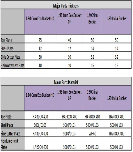
5.3 Material selection-
[image:4.595.323.547.483.739.2] [image:4.595.76.246.580.737.2]© 2016, IRJET | Impact Factor value: 4.45 | ISO 9001:2008 Certified Journal
| Page 1427
5.4. Digging forces
Bucket penetration into a material is achieved by the bucket curling force (FB) and arm crowd force (FS). The rating of these digging forces is set by SAE J1179 standard “Hydraulic Excavator and bucket : Digging Forces” [6].These rated digging forces are the forces that can be exerted at the outermost cutting point (that is the tip of the bucket teeth). These forces can be calculated by applying working relief hydraulic pressure to the cylinders providing the digging force.
Fig. 5 Forces on bucket
Fig. 6 shows the measurement of bucket curling force FB,arm crowd force FS, the other terms in the figure dA, dB, dC, dD, dD1, dE, and shows the distances as shown in Fig. 2. According to SAE J1179: Maximum radial tooth force due to bucket cylinder (bucket curling force) FB is the digging force generated by the bucket cylinder and tangent to the arc of radius dD
Where DB is the end diameter of the bucket cylinder in(mm) and the working pressure is p in MPa or N/mm2 and other distances are in mm and remains constant. Equation (4) determines the value of the bucket curl or breakout force in N. Now let us determine the maximum radial tooth force due to arm cylinder FS. Maximum tooth force due to arm cylinder is the digging force generated by the arm cylinder and tangent to arc of radius dF.
Where, dF is the sum of bucket tip radius (dD) and the arm link length in mm, and DA is the end diameter of the arm cylinder in mm. When the assembly of proposed 3D model is placed in the maximum breakout force
The calculated breakout Force (Fb) =261.2KN and
Calculated Arm Crowd force (Fs) =248.2KN
.
[image:5.595.75.249.256.417.2]5.5. Comparison of excavator models
Table -4: shows the compares on of physical dimensions, bucket specifications and forces of the designed excavator with the standard excavators
.
Table -05 Comparison of bucket parameters
6. FINITE ELEMENT ANALYSIS OF AN EXCAVATOR
BUCKET
6.1 FEA procedure in ANSYS
While analyzing the whole excavator attachment modeled in three dimensions in ANSYS the following procedure is used.
1. Export the model / assembly
2. Specify materials
3. Add constraints:
[image:5.595.308.553.300.561.2]© 2016, IRJET | Impact Factor value: 4.45 | ISO 9001:2008 Certified Journal
| Page 1428
5. Specify contact conditions:6. Meshing:
6.2 Load Cases & deformations
-
Load 1/3 offset Case
[image:6.595.310.544.250.351.2]Fig. 6 Bucket deformation at 1/3 load
Fig. 7 Von mises stress analysis of bucket at 1/3 load
Fig. 12 Von misses stress analysis of bucket at 1/3 load
Fig. 8 Bucket deformation at full load
[image:6.595.31.258.319.428.2]Fig. 9 Von mises stress analysis at full load
Fig. 10 Von misses stress analysis of bucket at full load
[image:6.595.310.532.451.529.2]7. COMPARISON OF CURRENT BUCKET AND
PROPOSED BUCKET-
Table 5-Bucket comparison
8. CONCLUSION
1.
The Project basically focused on an Analysis and Optimization of Excavator Bucket .The analysis of chassis model was done in ANSYS 15.0 Workbench. The results were supported with an experimental validation for verifying the actual distortion and FEA results. Following are concluding remarks based on the analysis performed on bucket model & Bucket validation at ARAI.2.
Model of Bucket is analysed under 4 different loading conditions to find out the bucket distortion, and bucket distortion is compared with regular bucket. It is observed that the stresses in 1.8 cum design when analyzed for 1/3 offset and for full offset are lesser than 1.9 cum Current production bucketVon-mises Stresses is done at 200 MPa.
Actuator force applied is 209.2 KN
Ram details Differs Total Deformation
of 22 mm
[image:6.595.36.225.472.551.2]© 2016, IRJET | Impact Factor value: 4.45 | ISO 9001:2008 Certified Journal
| Page 1429
3.
In bucket validation we observed that Bucket strength& life is more as compared with previous bucket.
REFERENCES
1] Bhaveshkumar P. PATEL1, Jagdish M. PRAJAPATI, evaluation of bucket capacity, digging force calculations and static force analysis of mini hydraulic backhoe excavator
[2] Manisha P. Tupkar, 2Prof. S. R. Zaveri Design and Analysis of an Excavator Bucket International Journal of Scientific Research Engineering & Technology (IJSRET), ISSN 2278 – 0882 Volume 4, Issue 3, March 2015,
[3]Catalogs JCB India ltd.
[4]MEHTA GAURAV K, Design & Development of an Excavator attachment, M. Tech. thesis, Institute of Technology, Nirma University of Science and Technology, Ahmedabad-382 481, May 2008, pp 1.
[5]OFF-HIGHWAY RESEARC H, Equipment Analysis: India Backhoe Loaders, March 2008, pp 2.
[6]PATRICK SEA N ROWE, Adaptive Motion Planning for Autonomous Mass Excavation, Ph. D. Thesis, The
[7]Robotics institute of Carnegie Mellon, Pittsburg pensyl vania15213 ,January 1999 ppi
[8] SAE INTERNATIONALS, SAE J1179: Hydraulic, Excavator and Backhoe Digging Forces, 400 Common wealth Drive, Warrendale, PA, 1990, pp 1
[9] Bhaveshkumar P. Patel and Dr. J.M.Prajapati,”A ReviewOn Kinematics Of Hydraulic Excavator’s Backhoe Attachment”, International Journal of Engg.Science and Technology (IJEST) Vol.No.3.IssueNo.3.March 2011
10) Modeling and Static Analysis of Backhoe Excavator Bucket(Mr.Swapnil S. Nishane 1, Dr. S.C. Kongre 2, Prof. K.A. Pakhare) (5)International Journal of Research in Advent Technology, Vol.4, No.3, March 2016 E-ISSN: 2321-9637 Available online at www.ijrat.org
11) static analysis of mini hydraulic backhoe excavator attachment using fea approach issn 2278 – 0149
www.ijmerr.com ,vol. 1, no. 3, october 2012 © 2012
ijmerr. all rights reserved bhaveshkumar p patel1* and j m prajapati2
AUTHOR PROFILE:
Mr. Sujit A. Lomate received the bachelor of Engineering from RIT, Islampur in 2013. He is now pursuing M.E. in Design Engineering from Dhole Patil College of Engg. Pune.
Prof. Siddaram Biradar is allied with Dhole Patil College of Engineering Pune, department of mechanical engineering as Assistant Professor. He had completed his M.E in Design engineering from SPPU Pune and working as assistant professor in Dhole Patil College of Engineering Pune. Since 4.5 years.
Prof. Ketan K Dhumal allied with Dhole Patil College Of Engineering Pune, department of mechanical engineering as Assistant Professor. He had completed his ME (Design) fromFr. C. Rodrigues Institute of Technology, vashi, Mumbai University in 2013. The author is associated with teaching from 4.5 years. His area of Interest are Casting Design and Simulation ,Analysis of mechanisms, Vibration Measurement. Author presented one international paper on casting design and simulations.