© 2016, IRJET ISO 9001:2008 Certified Journal Page 1053
Study for improving the performance of the Step-Back Building with
Bracings
R. Prasath
1, A. Joshua Daniel
21
M. Tech, Department of Civil Engineering, SRM University, Tamil Nadu, India.
2Assistant Professor, Department of Civil Engineering, SRM University, Tamil Nadu, India
.
---***---Abstract –
The study involves with improving theperformance of the step-back building with bracing by performing Response Spectrum analysis. The step-back building are more vulnerable to seismic force as they have various irregularities such as mass irregularity, stiffness irregularity and vertical geometric irregularity. Bracing is a lateral load resisting elements the can be used in structures to increase its stability. The variations in parameters such as Axial Load, Shear Force, Bending moment and Torsional force with and without bracings are compared in this study.
Key Words: Step-back building, Bracings, Response spectrum
analysis, Irregularity, Axial Load, Shear force, Bending moment, Torsional Force.
1. INTRODUCTION
In Hilly areas due to scarcity of flat land, majority of the buildings is constructed on the slopes with irregular structural configuration having foundations at different levels. Such buildings poses structural and constructional problems. Singh Y, et.al [1] studied the Behaviour of Buildings located on slopes. They was observed that these buildings have significantly different dynamic characteristics than buildings on flat ground. The storey immediately above the road level, in case of step-back buildings, are particularly vulnerable to earthquake action.
There are 3 main configuration of buildings build on hill slopes are Set-back building, Step-back building, Set-back back building. The study mainly concentrates on Step-Back building as they are more vulnerable to seismic force than other configurations.
Stepping back of building towards hill slope results in unequal column heights which causes severe stiffness irregularity. These buildings when subjected to lateral loads in cross-slope direction there is significant torsional coupling due to varying lateral stiffness on uphill and downhill side frames. The torsional behaviour of these buildings is much more complex than that of buildings on flat ground due to shifting in centre of stiffness and centre of mass [2]. The shorter columns on uphill side of a storey attracts the shear,
which is usually much higher than their capacity and may result in shear failure.
These Step-back building are analyzed for seismic forces with Bracings at favorable location and the results are compared.
2. MODELING
The modelling and Analysis is done using Structural Analysis and Package (SAP2000) Software.
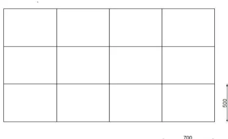
The dimension of the building were taken as 15m x 28m. The plan and elevation of building adopted is shown in Fig -1, Fig -2.
The G+5 Building is modelled and analysed to compare its stability with and without Bracing at different location. Whereas the loading pattern and specification of the materials remain same.
[image:1.595.315.549.484.626.2]© 2016, IRJET ISO 9001:2008 Certified Journal Page 1054
Fig -2: Elevation View (All units are in Centimetre)
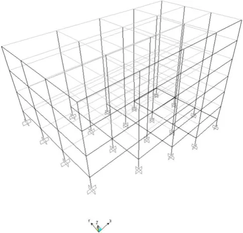
Fig -3: 3-D View of Control structure
2.2 ASSUMPTIONS
The special moment resisting frame building is assumed to be built on medium soil site which falls under seismic zone IV. The importance factor of 1 is been considered. The Step-Back building is built on a slope terrain of 24 degree, with a floor to floor Height of 3.1 meter. M20 Grade of concrete and Fe415 Grade steel are considered.
The loading parameters for dead and live loads, based on IS 875 (part 1):1987 and IS 875(part2):1987. The loading considered in the analysis are as follows.
Live load (floor) = 3 KN/m2
Live load (roof) = 1.5 KN/m2
Floor finish = 1 KN/m2
Roof finish = 1.5 KN/m2
Brick masonry = 20 KN/m3
The boundary condition is Fixed, Slab are modelled as thin shell element with the thickness of 200 mm, beam and column are modelled as frame elements. The dead load and live load are imposed on the slab. The earthquake loads is calculated as per IS 1893:2002.
The load combinations that are considered for the analysis are taken from IS1893:2002 to arrive at the worst combination.
2.3
BRACINGS
[image:2.595.40.282.310.542.2]Steel bracing is a structural Element that is used for resisting earthquake loads. They are economical, easy to erect, occupies less space and has flexibility to design to meet required strength and stiffness. The location of Bracings were selected on the basis of trial and error method. X type Bracings were used.
Table -1: Assumed Angle Section
Section Dimension (mm) Area (mm2)
Equal Angle ISA 150 X 150 X 18 5079
Unequal Angle ISA 200 X 150 X 15 5025
[image:2.595.316.550.380.624.2]2.4
BRACING LOCATIONS`
© 2016, IRJET ISO 9001:2008 Certified Journal Page 1055
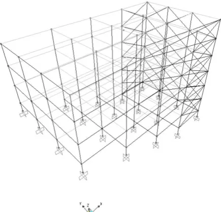
Fig -5: Case 2 (Bracings are provided along X-direction)
Fig -6: Case 3 (Bracings are provided along both X and Y-direction)
3. RESULTS AND DISCUSSIONS
3.1 ANALYSIS OF CONTROL STRUCTURE
Weight of the Building = 28752.73KN
Base Shear correction
Vb*/Vb in X-dir = 1.9895
Vb*/Vb in Y-dir = 2.4873
Base Reaction in X-dir = 1725.95 KN
Base Reaction in Y-dir = 1725.16 KN
Fundamental Time Period = 0.87878 Sec
After the analysis of control building a total of 8 columns failed to pass the check. 4 Columns of Frame A and
2 Edge columns of frame B and C failed for load combination 0.9DL – 1.5 EQy. These columns Failed Due to Shear Stress, Torsion and Bending Moment and are highlighted in the fig.3.
Fig -7: Location ofFailed Columns
3.2 Comparison
[image:3.595.310.522.159.334.2]The Analysis results of actual structure and braced structure are compared in terms of axial load, Shear force, bending moment and Torsional force at column level of the building. The maximum and minimum variations for the above forces are also indicated and the appropriate location of Bracing for stability of the structure is determined.
Table -2: Variation of Axial Load for Failed columns
Col
umn structure Control (KN)
Equal angle (%
Inc/Dec) Unequal angle (% Inc/Dec)
Case Case
1 2 3 1 2 3
A 757.19 -4 4 -2 -4 4 -2
B 843.01 0.1 2 0.1 0.1 2 0.1
C 843.01 0.1 2 0.1 0.1 2 0.1
D 757.19 -4 4 -2 -4 4 -2
E 1283.95 -1 2 1 -1 2 1
F 1283.95 -1 2 1 -1 2 1
G 1585.47 8 0.1 9 8 0.1 9
H 1585.47 8 0.1 9 8 0.1 9
Remark 9% Decrease 4% Increase 9% Decrease, 4% Increase
[image:3.595.40.258.367.575.2]© 2016, IRJET ISO 9001:2008 Certified Journal Page 1056
Table -3: Variation ofBending along X direction for Failed Columns
Col
umn structure Control (KNm)
Equal angle (%
Inc/Dec) Unequal angle (% Inc/Dec)
Case Case
1 2 3 1 2 3
A 285.11 -17 12 -17 -17 12 -17
B 162.99 -14 5 -20 -14 5 -20
C 162.99 -14 5 -20 -14 5 -20
D 285.11 -17 12 -17 -17 12 -17
E 98.79 53 2 52 53 2 52
F 98.78 53 2 52 53 2 52
G 166.38 47 8 51 47 8 51
H 166.38 47 8 51 47 8 51
Remark 53% Decrease, 20% Increase 53% Decrease, 20% Increase
The bending moment along X direction of column E, F, G, h decrease by 47 to 53 percentage when bracings are provided as in case 1 and case 3. But bending moment of column A, B, C, D increased. When bracings are provide as in case 2 all failed column showed a decrease of 2 to 12 percentage in bending moment.
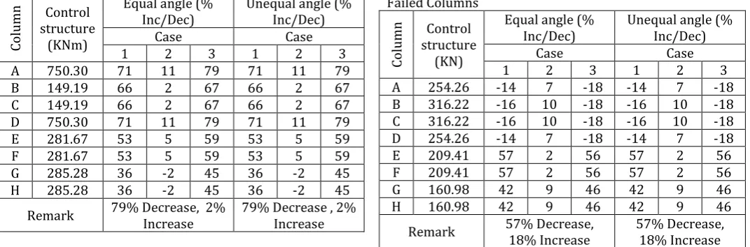
Table -4: Variation ofBending along Y direction for Failed Columns
Col
umn structure Control (KNm)
Equal angle (%
Inc/Dec) Unequal angle (% Inc/Dec)
Case Case
1 2 3 1 2 3
A 750.30 71 11 79 71 11 79
B 149.19 66 2 67 66 2 67
C 149.19 66 2 67 66 2 67
D 750.30 71 11 79 71 11 79
E 281.67 53 5 59 53 5 59
F 281.67 53 5 59 53 5 59
G 285.28 36 -2 45 36 -2 45
H 285.28 36 -2 45 36 -2 45
Remark 79% Decrease, 2% Increase 79% Decrease , 2% Increase
The bending in Y direction showed a considerable decrease of about 36 to 79 percentage on all failed columns when bracings are provided as in case 1 and case3. The decrease is more than that of the X direction. The reason for this variation of bending moment in X and Y direction is due to the slope of terrain which is along X direction. In case 2 the decrease of bending moment is less compared to case 1 and case 3.
Table -5: Variation of Shear Force along X direction for Failed Columns
Col
umn structure Control (KN)
Equal angle (%
Inc/Dec) Unequal angle (% Inc/Dec)
Case Case
1 2 3 1 2 3
A 742.67 71 6 75 71 6 75
B 266.61 70 7 75 70 7 75
C 266.61 70 7 75 70 7 75
D 742.67 71 6 75 71 6 75
E 515.34 59 6 65 59 6 65
F 515.34 59 6 65 59 6 65
G 286.44 33 -0.1 44 33 -0.1 44
H 286.44 33 -0.1 44 33 -0.1 44
Remark 75% Decrease, 0.1% Increase 75% Decrease, 0.1% Increase
The main reason for column failure in step-back building is due to shear force and bracings are provided to carry shear force from column [2]. Thus providing bracing as in case 3 the shear force along X direction on all failed column decreased by 44 to 75 percentage. Whereas there is not much change in shear force along X direction when bracings are provided as in case 2.
Table -6: Variation of Shear Force along Y direction for Failed Columns
Col
umn structure Control (KN)
Equal angle (%
Inc/Dec) Unequal angle (% Inc/Dec)
Case Case
1 2 3 1 2 3
A 254.26 -14 7 -18 -14 7 -18
B 316.22 -16 10 -18 -16 10 -18
C 316.22 -16 10 -18 -16 10 -18
D 254.26 -14 7 -18 -14 7 -18
E 209.41 57 2 56 57 2 56
F 209.41 57 2 56 57 2 56
G 160.98 42 9 46 42 9 46
H 160.98 42 9 46 42 9 46
Remark 57% Decrease, 18% Increase 57% Decrease, 18% Increase
[image:4.595.27.568.114.294.2] [image:4.595.32.568.415.592.2]© 2016, IRJET ISO 9001:2008 Certified Journal Page 1057
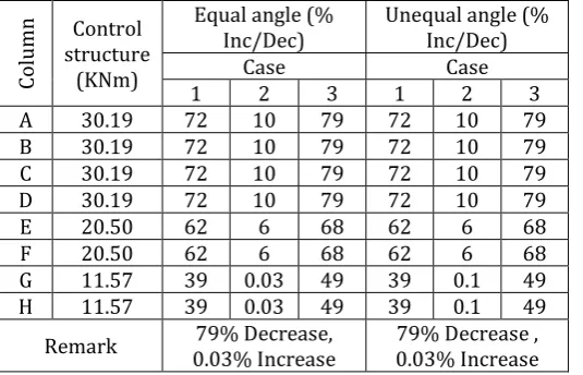
Table -7: Variation ofTorsion for Failed Columns
Col
umn structure Control (KNm)
Equal angle (%
Inc/Dec) Unequal angle (% Inc/Dec)
Case Case
1 2 3 1 2 3
A 30.19 72 10 79 72 10 79
B 30.19 72 10 79 72 10 79
C 30.19 72 10 79 72 10 79
D 30.19 72 10 79 72 10 79
E 20.50 62 6 68 62 6 68
F 20.50 62 6 68 62 6 68
G 11.57 39 0.03 49 39 0.1 49
H 11.57 39 0.03 49 39 0.1 49
Remark 0.03% Increase 79% Decrease, 0.03% Increase 79% Decrease ,
The slope of terrain is along X direction thus providing bracings along Y direction as in case 1 showed a decrease of 39 to 72 percentage of Torsional force in all failed columns.
4. CONCLUSIONS
Including bracing in step-back building showed improvement in the stability on step-back building. The shear force on all failed column decreased considerably by 44 to 75 percentage when the bracings are provided as in case 3. The Angle section both Equal and Unequal showed same percentage variation of forces and bracing can be used as lateral load resisting element along both the direction of the building.
REFERENCES
[1] Singh Y. and Phani Gade (2011), ‘Seismic Behavior of buildings located on slopes- Sikkim Earthquake’, 15 WCEE.
[2] Birajdar B.G. and Nalawade S.S. (2004), ‘Seismic analysis of buildings resting on sloping ground’, 13th World conference on Earthquake engineering, pp. 1472.
[3] Damodarasamy S.R., and kavitha S. (2013), ‘Basic of Structural Dynamics and Aseismic design’, PHI Learning Private Limited, Delhi.
[4] IS: 875 (Part 1) 1987, ‘Code of practice for Dead loads on buildings and structures’, Bureau of Indian Standard, New Delhi.
[5] IS: 875 (Part 2) 1987, ‘Code of practice for Live loads on buildings and structures’, Bureau of Indian Standard, New Delhi.
[6] IS: 1893 (Part 1) 2002, ‘Code of Criteria for earthquake resistant Design of structures’, Bureau of Indian Standard, New Delhi.
[7] Ravi Kumar C.M., Babu Narayan K.S., Sujith B.V., Venkat Reddy D.(2012), ‘Effect of Irregular
Configurations on Seismic Vulnerability of RC Building’, Architecture Research DOI: 10.5923. [8] SAP2000, ‘Integrated software for structural
analysis and design’, computers and structures Inc, Berkeley, CA, USA.