© 2016, IRJET | Impact Factor value: 4.45 | ISO 9001:2008 Certified Journal
| Page 694
Performance Investigation of Inverter fed 7-Phase Induction Motor
Drive
G.RENUKA DEVI
Department of Electrical & Electronics Engineering,
Manakula Vinayagar Institute of Technology, Puducherry-605107,India Email: renukadeviayyappan@gmail.com
---***---Abstract -
This paper presents the PerformanceInvestigations of 7-Phase Inverter fed Induction Motor Drive. Compared to three-phase drive multi-phase induction motor drive possess several advantages, reduced current per phase, torque ripple frequency is high and amplitude of torque ripple is low, resulting lower operating noise and mechanical vibration. The total power rating of multi-phase motors in the same frame can be increased significantly without overloading a single phase and better fault tolerant capability. The 7th harmonic fed 7-phase drive is proposed in this paper. The performance of the 7 -phase VSI is studied with the varying modulation index. The VSI fed multi-phase drive is analyzed for different load conditions. The simulation results are presented for different modulation indices and compare the performance of the drives are presented.
Key Words: 7th harmonic injection, multi-phase drive,
pulse width modulation, switching technique, voltage source inverter.
1. INTRODUCTION
Multi-phase machine drives are fast increasing in recent years, due to their several inherent benefits such as lower torque pulsation, reduction in harmonic currents, and reduced current per phase without the need to increase the phase voltage, greater reliability, fault tolerant feature and increased power in the same frame as compared to three phase machine. They are mostly used in high power applications, such as ship propulsion, electric aircraft, and electric/hybrid electric vehicles etc. Multi-phase motors require multi-phase voltage source inverter (VSI) for their input supply. An inverter topology uses two switches connected in series as one inverter pole. The number of inverter poles depends on number of phases. For example, a three-phase inverter will have three inverter poles whereas a five-phase inverter will have five inverter poles. The switching pattern of the three phase inverter should be modified according to the number of phases. For three phase inverters, the sinusoidal pulse width modulation (SPWM) method, space vector pulse width modulation (SVPWM), harmonic injection method and offset injection method are extensively discussed in literature [1-22].The SPWM and SVPWM techniques are extended for multi-phase VSI [1-16].
The SPWM schemes are more flexible and easy to implement. However the output waveforms contain more harmonics resulting in reduced fundamental component and efficiency. To achieve the better output voltage, the several space vector pulse width modulation (SVPWM) techniques are discussed, such as conventional SVPWM, space vector disposition SVPWM, discontinuous SVPWM and multi-dimensional SVPWM [4-17]. The complexity involved in the SVPWM technique is more for higher number of phases. The inverter output voltage space vectors changes to 2n states, since there are 2n different switching configurations. Hence the SVPWM has complicated controlling algorithm for sector identification, look up table, angle information and voltage space vector amplitude measurements. Therefore a simple and efficient switching technique is needed for multi-phase voltage source inverter which would overcome the complexity involved with higher number of phases. In this paper to investigate the performance of the 7-phase VSI with the improved PWM techniques namely harmonic injection method, which is commonly used for three phase VSIs can be used for multi-phase VSIs. In the harmonic injection method the linear modulation range is extended by adding the mth harmonic component with respective phase of the reference phase voltages and the fundamental output voltage is increases without moving into the over-modulation region [18-22].
The main contribution of this paper is to detail study of harmonic injection PWM technique for multi-phase voltage source inverter. The performance of the inverter is investigated with these switching technique and the results are presented for 7-phases. Based on the inverter fed simulation results the multi-phase drive is analyzed in terms of current/phase, output power and torque frequency.
2.
POWER CIRCUIT OF MULTI-PHASE VSI
The power circuit of 7-phase VSI is shown in Fig.1. The circuit consists of 7 half-bridges, which are mutually displaced by 2π/7 degrees to generate the 7-phase voltage waves. The input dc supply is obtained from a single phase or 3-phase utility power supply through a diode-bridge rectifier. The voltages Va, Vb, Vc, Vd, Ve, Vf,Vg are the inverter
© 2016, IRJET | Impact Factor value: 4.45 | ISO 9001:2008 Certified Journal
| Page 695
[image:2.595.314.563.63.295.2]other pole to create the required 7-phase output voltages. The load phase voltages and inverter pole voltages is as given in the following relations (1)
Fig - 1: Power circuit of 7-phase VSI
1 1 ( ) 1 1 ( ) 1 1 ( ) 1 1 ( ) 1 1 ( ) 1 1 ( ) 1
aN a b c d e f g
bN b a c d e f g
c N c a b d e f g
dN d a b c e f g
e N e a b c d f g
fN f a b c d f g
g N
n
V V V V V V V V
n n
n
V V V V V V V V
n n
n
V V V V V V V V
n n
n
V V V V V V V V
n n
n
V V V V V V V V
n n
n
V V V V V V V V
n n n V n
Vg 1(Va Vb Vc Vd Ve Vf)
n
(1)
The 7th harmonic injection method with simulation results of 7th harmonic injection fed drives are discussed detail in the following sections.
3.
SINUSOIDAL PWM WITH 7th HARMONIC
INJECTION
To eliminate the 3rd harmonic component in the output of the three phase voltage source inverter, the 3rd harmonic is injected to the sinusoidal reference voltages [1]. This would increase the maximum fundamental output voltage without moving into the over-modulation region. By analogy, the linear modulation range can be extended by injecting the 7th harmonic component for 7-phase VSI.
Fig - 2: Block diagram of sinusoidal PWM with nthharmonic
injection
The 7th-harmonic injection reduces the peak of the
7-leg reference voltages and hence the modulation index can be moved beyond the value of 1 without entering into over-modulation region. The block diagram of sinusoidal PWM with 7th harmonic injection of a 7-phase VSI is shown in Fig.2. In the 7-phase VSI (Varef, Vbref, Vcref, Vdref,Veref,Vfref,Vgref) are
reference phase voltages displaced by α=(2π/7) degrees. The reference sinusoidal signals are added with 7th harmonic
component to obtain a non sinusoidal modulating signal. The carrier based modulating signal is compared with the relational operator. The intersections between the modulating signals and the carrier signals give the opening and closing time of inverter switches. The best possible 7th
-harmonic injection for the 7-phase VSIs is achieved using (2).
7 ( 7 )
7 ( 7 )
7 ( 7 )
7 ( 7 )
7 ( 7 )
(
[ cos cos 7 ]
[ cos( ) cos 7 ]
[ cos( 2 ) cos 7 ]
[ cos( 3 ) cos 7 ]
[ cos( 4 ) cos 7 ]
t h
t h
t h
t h
t h
aref har dc
bref har dc
cref har dc
dref har dc
eref har dc
f ref
v V M wt M wt
v V M wt M wt
v V M wt M wt
v V M wt M wt
v V M wt M wt
v 7 7 ) 7 ( 7 )
[ cos( 5 ) cos 7 ]
[ cos( 6 ) cos 7 ]
t h
t h
dc har
gref har dc
V M wt M wt
v V M wt M wt
(2)
where M – Modulation index 0M1
M7 – Modulation index of the 7th harmonic component.
The 7th harmonic component has no effect on the value of the
reference waveform expression when wt[2k1] / 2 n,
since cos [ [2n k1] / 2 ] n 0 for all k. where k=0 to n Hence
M7 can be chosen to make the peak magnitude of the
reference waveform defined in (2) occur where the nth
[image:2.595.48.272.170.460.2]© 2016, IRJET | Impact Factor value: 4.45 | ISO 9001:2008 Certified Journal
| Page 696
in turn, assure the maximum possible value for the fundamental component. The reference voltages
v
a ref( 7thhar)reaches maximum when
( 7 )
7
sin 7 sin 7 0
h a ref t har
dc dc
dv
MV wt M V wt
dwt
(3)
where
wt
/ 2
n
From (3)7
sin( / 2n)
M M
n
(4)
Under these conditions, the maximum possible non sinusoidal modulating signal is given by (5)
( 7 )
sin( / 2 )
cos cos
th
aref har dc dc dc
n
v MV wt M V nwt V
n
(5)
From equation (5) M is 1
cos( / 2 )
M
n
(6)
4.
SIMULATION RESULTS
The 7-phase inverter is simulated with the above said switching scheme and the results are observed. The input DC is set to 1 volt, switching frequency of the VSI is chosen as 5 kHz and the fundamental frequency is set to 50 Hz. The 7-phase induction motor parameters are shown in Appendix. The 7 -phase VSI is simulated with the pulses obtained by harmonic injection technique. Figs. 3 and 4 show the results for five-phase VSI. Fig. 3(a) shows the fundamental, 7th harmonic component waveform and the resultant modulating signal for a modulation index of 1. It is seen that the peak value of the modulating signal is less than 1. It will reach ±1, when the modulation index
M
1/ cos( / 2 )
n
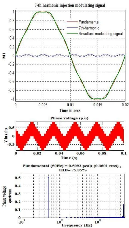
,according to expression (4). Also this would increase the maximum fundamental output voltage without moving into the over-modulation region. The output phase voltage and its spectrum are shown in Fig.3(b). It is seen that the output fundamental rms value is 0.3544 p.u. (0.5013 p.u. peak) and THD is 76.78%.The simulation is repeated for the maximum modulation index of 1.0257 and the results are shown in Fig.4 (a) and Fig.4(b). It is observed that the output fundamental rms value is 0.3601p.u. (0.5092 p.u. peak) and THD is 75.05%. It is seen that the maximum fundamental output voltage is increased by 2.57% for the maximum modulation index. Table 1 shows the comparison of fundamental voltage and THD for 7-phase VSI. It is seen increasing modulation index fundamental voltage is increasing THD is decreasing. The harmonic injection fed 5-phase drive is shown in Fig.5 in that case DC voltage is set to
730 Volts. The corresponding transient response of the drive is shown in Fig.6. From the simulation results when increasing phase numbers reduced current/phase, increased power in the same frame and increasing torque frequency are observed.
(a)
[image:3.595.310.547.175.720.2](b)
© 2016, IRJET | Impact Factor value: 4.45 | ISO 9001:2008 Certified Journal
| Page 697
Fig - 4: 7th harmonic injection with MI-1.0257 (a) Reference signal, 7th harmonic component and modulation signal (b) Phase voltage and its spectrum
TABLE-1:FUNDAMENTAL VOLTAGE (PU) AND THD FOR 7-PHASE VSI
MI
7-phase VSI
Fundamental voltage(Volts)
THD(%)
0.2 0.0964 269.04
0.4 0.2805 173.56
0.6 0.2978 128.89
0.85 0.3981 99.31
1 0.5013 76.78
[image:4.595.314.549.103.405.2]1.0257 0.5092 75.05
Fig - 5: Simulation results for 7-phase machine with 5 Nm load condition
Fig - 6: Transient response of 7-phase induction motor drive
5.
CONCLUSIONS
[image:4.595.310.553.450.622.2] [image:4.595.29.288.556.735.2]© 2016, IRJET | Impact Factor value: 4.45 | ISO 9001:2008 Certified Journal
| Page 698
power in the same frame and increasing torque frequency are observed. Further the harmonic injection method eliminates the need for complex control algorithm and its simple calculation makes it easy to implement in digital platform and admirable selection for high power applications.
APPENDIX
PARAMETERS OF THE 7-PHASE INDUCTION MOTOR
PARAMETERS VALUES
Power 1 hp
Voltage 220 V
Phase 7-phase
Frequency 50 Hz
No. of poles 4
Stator resistance (Rs) 10 ohm
Rotor resistance (Rr) 6.3 ohm
Stator inductance (Ls) 0.04 mH
Rotor inductance (Lr) 0.04 mH
Mutual inductance (Lm)
1.47 mH
Inertia (J) 0.03 kg.m^2
Friction (F) 0.0015N.m.s
REFERENCES
[1] G.D.Holmes, T.A.Lipo, “Pulse Width Modulation for Power
Converters - Principles and Practice,” IEEE Press Series on Power Engineering, John Wiley and Sons, Piscataway, NJ, USA, 2003.
[2] Bimal K.Boss Modern power electronics and ac drives,
Prentice Hall ,2002.
[3] G.Renukadevi and K.Rajambal, “Novel Carrier-Based
PWM technique for n-Phase VSI,” International Journal of Energy Technologies and Policy, 2011, pp. 1-9.
[4] Zhou K and Wang D, “Relationship between Space
vector modulation and Three-phase carrier based PWM - A comprehensive analysis”, IEEE Trans. Ind. Electron.,2002,49,(1),pp 186-196.
[5] J. S. Kim and S. K. Sul, “A novel voltage modulation
technique of the space vector PWM,” in Conf. Rec. IPEC’95, Yokohama, Japan, 1995, pp. 742–747.
[6] Kelly, J.W., Strangas, E.G., and Miller, J.M.: ‘Multi-phase
inverter analyses. Proc. IEEE Int. Electric Machines and Drives Conf. IEMDC, Cambridge, 2001, pp. 147–155.
[7] A.Iqbal, E.Levi, “Space vector modulation scheme for a
five-phase voltage source inverter,” Proc. European Power Electronics (EPE) Conf., Dresden, Germany,2005, CD-ROM paper no. 0006.pdf.
[8] A.Iqbal, E.Levi, “Space vector PWM techniques for
sinusoidal output voltage generation with a five-phase voltage source inverter,” Electric Power Components and Systems,2006, vol. 34 no. 2.
[9] D.Casadei, G.Serra, A.Tani, L.Zarri, “Multi-phase inverter
modulation strategies based on duty-cycle space vector approach,” Proc. Ship Propulsion and Railway Traction Systems Conf. Bologna, Italy, 2005, pp. 222-229.
[10] J.W.Kelly, E.G.Strangas, J.M.Miller, “Multi-phase space
vector pulse width modulation,” IEEE Trans. on Energy Conversion, vol. 18, no. 2,2003, pp. 259-264.
[11] Iqbal and S. Moinuddin, “Space vector model of a
five-phase voltage source inverter,” in Proc. IEEE Int. Conf. Ind. Technol. ICIT,2006, Mumbai, India, Dec.15–17, pp. 488–493, Paper IF 002909.
[12] G.Grandi, G. Serra, A. Tani, “Space vector modulation of
a seven-phase voltage source inverter,” in Proc. of Symposium on Power Electronics, Electrical Drives, Automation & Motion SPEEDAM, 2006, pp. S8-6 - S8-13.
[13] D.Casadei, F. Milanesi, G. Serra, A. Tani, L. Zarri, “Space
Vector Modulation Based on a Multidimensional Approach for Multiphase Inverters with an Odd Number of Phases,” Power ElectronicsSpecialists Conference(PESC), pp. 1351-1357, 2008.
[14] Ruhe Shi, H. A. Toliyat, “Vector Control of Five-phase
Synchronous Reluctance Motor with Space Pulse Width Modulation for Minimum Switching Losses,” 36th Industry Applications Conference AnnualMeeting (IAS),
vol. 3, pp. 2097-2103, 30 Sept.- 4 Oct. 2001.
[15] Fei Yu, Xiaofeng Zhang, Huaishu Li, Zhihao Ye, “The
space vector PWM control research of a multi-phase permanent magnet synchronous motor for electrical propulsion,” International Conference of Electrical Machines and Systems (ICEMS), vol. 2, pp. 604-607, Nov.2003.
[16] Hyung-Min Ryu, Jang-Hwan Kim, Seung-Ki Sul, “Analysis
of Multi-Phase Space Vector Pulse Width Modulation Based on Multiple d-q Spaces Concept,” The 4th International Power Electronics and Motion Control Conference (IPEMC 2004), vol. 3, pp. 1618-1624, 2004.
[17] S.Xue, X. Wen, Z. Feng, “A novel multi-dimensional
SVPWM strategy of multiphase motor drives,” Proc. Power Electronics and Motion Control Conf. EPE-PEMC,
pp. 931-935, 2006.
[18] G.Renukadevi and K.Rajambal, “Generalized Model of
Multi-Phase Induction Motor Drive using Matlab/Simulink,” International IEEE PES Conference Innovative Smart Grid Technologies,Kerala-India,2011.
[19] E.Levi, “Multiphase Electric Machines for Variable Speed
Applications,” IEEE Transactions on Industrial Electronics, vol. 55, no. 5, pp. 1893-1909, MAY 2008.
[20] G.Renukadevi and K.Rajambal, “Field Programmable
Gate Array Implementation of Space-Vector Pulse-Width Modulation Technique for Five-Phase Voltage Source Inverter,” IET Power Electronics, ISSN 1755-4535, pp.376-389.
[21] G.Renukadevi and K.Rajambal, “Comparison of Different
© 2016, IRJET | Impact Factor value: 4.45 | ISO 9001:2008 Certified Journal
| Page 699
[22] G.Renukadevi and K.Rajambal, “Performance
Investigation of Multi-Phase VSI with Simple PWM Switching Techniques,” International journal of Engineering,Vol. 26, No. 1,pp.451-458, March-2013.