AUTOMATED WIRE LENGTH MEASUREMENT AND CUTTING
SYSTEM
Dr. Madhukar S. Chavan1*, Mohini D. Shinde2, Asmita M. Thorat3, Suraj H. Shinde4
1,2,3,4
Electronics and Telecom. Engg., P. V. P. I. T. Budhgaon, Sangli, Maharashtra, India *corresponding author: Dr. Madhukar S. Chavan
ABSTRACT
In this paper we proposed the system for automated wire length measurement and cutting system. Wire cutting system includes length measurement of the wire that uses number of revolutions of DC motor shaft. After length measurement of wire, cutting unit cuts the wire as per user specifications. The proposed system significantly deals with accuracy of wire length measurement and cutting. The system is fully automatic. The proposed system “Wire cutting and Measurement System” is fully automatic and can be operated by non-technical person. In industrial applications it saves time, material and manpower. An experimental result shows that the proposed system outperforms the accurate function which independent of type and category of the wire. System prototype can be changed with few changes in software and hardware for different wire categories and their coatings.
Keywords: Microcontroller, Embedded C Programming, Cutting Unit, DC Motors.
1. Introduction
In 21st century the electronics technology has raised at its glory. Comparing the initial technology and present technology there is vast development in field of electronics. In Industrial, 9electronics sector and household there is inherent need of electric wires. The types of wires vary from single strand wire to the optical fiber cables. The required wire may be in different size and different length. As per industrial demand, we have developed the system which automatically measures the length of the wire and cuts it as per specified length. This system can be easily handled by the subordinates and the unskilled persons in industry. The main components of the system are: Micro-controller, DC motors and cutting unit. Microcontroller is acting as a brain of our system [1]. In the proposed system rotating shaft of fiber DC motor is used for estimation of the length [2]. Subsequently the system uses softwares like Proteus, Keil µ vision, Flash Magic for microcontroller programming etc.
GE-International Journal of Engineering Research
Vol. 5, Issue 3, March 2017 Impact Factor- 5.613 ISSN(O): 2321-1717, ISSN(P): 2394-420X
2. Block Diagram of the System
Fig.1 Block diagram of automatic wire cutting machine
The Microcontroller is brain of system that handles all input and output devices. We can interface the LCD display, input keypad and other required peripherals to the microcontroller. The system uses 16x2 alphanumeric Liquid Crystal Display (LCD) that displays the input given by user. The cutting tool is operated by relay switching through microcontroller. The process provides great accuracy with sufficient speed. The system
provides user friendly data input through keyboard. The selection of input will be processed by microcontroller and displayed on LCD display for confirmation of inputs.
3. Hardware Components
a. Microcontroller
b. 16×2 LCD Modules
A liquid crystal display (LCD) is a flat panel display that uses the light modulating properties of liquid crystals (LCs). LCD Modules can present textual information to user. The 2x16 character LCD interface card supports both modes 4-bit and 8-bit interface and also facility to adjust contrast through trim pot. In 4-bit interface 7 lines needed to create 4-bit interface; 4 data bits (D0 – D3), three control lines, address bit (RS), read/write bit (R/W) and control signal (E). 16×2 LCD module is a very common type of LCD module that is used in 8051 based embedded systems. It consists of 16 rows and 2 columns of 5×7 or 5×8 LCD dot matrices. It is available in a 16 pin package with back light, contrast adjustment function and each dot matrix has 5×8 dot resolution.
c. Key Pad
The 4x4 matrix keypad has eight input/output ports. As per user requirement input is given through keypad i.e no. of pieces required and length for one piece of wire in meters. The status of each key can be determined by the process called scanning. In normal case all the column pins are pulled up (high state) by external or internal pull up resistors. Matrix Keypad is made by arranging push button switches in row and columns.
d. Motor Drives
L293D is a dual H-Bridge motor drive. With one IC, we can interface two DC motors which can be controlled in both clockwise and counter clockwise directions. L293D has output current of 600mA and peak output current of 1.2A per channel. Moreover for protection of circuit from back EMF, output diodes are included within the IC.
Table 1: Truth Table for DC Motor
A B Description
0 0 Motor stops or break
0 1 Motor run anti-clockwise
1 0 Motor run clockwise
1 1 Motor stops or breaks
For above truth table enable has set to 1. Motor power supply voltage is 12volt. Three pins are needed for interfacing a DC motor (A, B, Enable). To enable output completely, connect Enable to VCC and only 2 pins needed from controller to make the motor work.
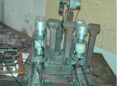
4. Practical Automated Wire Cutting System
Fig.4 Automated Wire Cutting System
[image:4.595.99.497.295.589.2]4. Software Design
a. Keil µ Vision: Keil Software provides software development tools for 8051 based microcontrollers. With the Keil tools, that can generate embedded applications for virtually every 8051 derivative. Keil Software development tools for the ARM microcontroller family supports professional applications engineer as well as new learners. The industry-standard Keil C compilers, macro assemblers, debuggers, real-time kernels, and single-board computers support all ARM-compatible derivatives. µ Vision is an IDE (Integrated Development Environment) that helps to write, compile, and debug embedded programs. It encapsulates the project manager, a make facility, tool configuration, editor etc.
b. Flash Magic: NXP Semiconductors has produced a range of Microcontrollers that feature
both on-chip Flash memory and the ability to be reprogrammed using In-System Programming technology. Flash Magic is Windows software from the Embedded Systems Academy that allows easy access to all the ISP features provided by the devices. These features include:
Erasing the Flash memory (individual blocks or the whole device)
Programming the Flash memory
Modifying the Boot Vector and Status Byte
Reading Flash memory
Performing a blank check on a section of Flash memory
Reading the signature bytes
Reading and writing the security bits
Direct load of a new baud rate (high speed communications) Sending commands to place device in Boot loader mode.
5. System Flow chart
Fig. 5 system flowchart
7. Experimental Results
Table 2: Practical length of the wire
[image:7.595.95.502.258.641.2]
Fig.6 Ideal Performance of the system
Sr. No. Input
(meters)
Output (meters) Error
(cms)
Ideal Practical
1 1 1 1.008 0.8
2 2 2 1.007 0.7
3 3 3 3.007 0.7
4 4 4 4.006 0.6
The input length specified by the customer and the ideal expected length to be cut is shown in the Fig.6.
Fig.7 Practical Performance of the system
The combined performance is shown in the Fig.8. From figure it is seen that the practical (actual) performance of the system is close to the ideal performance. The small amount of error is only due to mechanical design limitations. The appropriate compensation eliminates the errors.
8. Conclusion
The proposed system is fully automatic and can be operated by non-technical person. In industrial applications it saves time, material and manpower. An experimental result shows that the proposed system outperforms the accurate function which is independent of type and category of the wire. System prototype can be changed with few changes in software and hardware for different wire categories, wire sizes and their coatings.
References
1. Priyanka D. Patil1, Dr. Madhukar S. Chavan, ARM Controller based Restaurant Automation System using Zigbee Technology, International Journal of Advanced Research in Electrical, Electronics and Instrumentation Engineering ( IJAREEIE) ISSN: 2278-8875, Volume. 6, Issue 2,February 2017.
2. Rushikesh Gadale, Mahendra Pisal, Sanchit Tayade, S.V. Kulkarni, PLC Based Automatic Cutting Machine, International Journal of Engineering and Technical Research (IJETR) ISSN: 2321-0869, Volume-3, Issue-3, March 2015.
3. A.Patil,S.Nikumbh,S.Kumar,S.Saraf, Automated Wire Cutting and Crimping Machine With Wire Color Detection System Using Image Processing and Data Sequencing, International Journal of Advances in Science Engineering and Technology, ISSN: 2321-9009 Volume- 2, Issue-2, April-2014.
4. Karnopp, Dean C., Donald L. Margolis, Ronald C. Rosenberg, System Dynamics,
Modeling and Simulation of Mechatronic Systems, 4th Edition, Wiley, 2006.
5. Zhou H, Wu G. The programming based on embedded real time operating system, Beijing: Beihang University press, 2006.
6. Wiring Harness Assembly Detection System Based on Image Processing Technology,
Gumingshi School of Electrical Engineering and Automation Shanghai University Shanghai, China, 2005.