IMPll-B ARPANET INTERFACE
GENERAL DESCRIPTION:
Roy Hugenberger 13 February 1979
The IMPll-B is a microprocessor controlled interface which
provides a full duplex serial connection between a PDPll Computer System and the Interface Message Processor (IMP) of the Advanced Research Project Agency Network (ARPANET). The IMP is the
communications processor that interfaces the Host Computer to the ARPANET. The IMPll-B ARPANET INTERFACE allows the PDPll user, with the addition of appropriate software, to communicate with other Host machines on the ARPANET. The IMPll-B will support both the local (~30 ft.) distant (~2000 ft.) host operation of ARPANET IMP interface.
FEATURES:
*
Compact design - 2-Hex size SPC modules plus a rack mounted indicator and cable connection panel.*
Microprocessor based (KMCll).*
Full duplex operation.*
16 bit UNIBUS NPR transfers.*
Indicator Panel.*
Switch selectable for either the IMP's local or distant interface.*
Static and dynamic diagnostic software and ARPANET test program.OPERATION:
.. The IMPll-B logic consists of two modules, a KMCll-A
microprocesso~ module and a line termination module. To
initialize the IMPll-B, the PDPll operating software loads the Digital supplied firmware code into the KMCll. Once this
firmware is loaded and started, the IMPll-B is operational. A user program issues a command to the IMPll-B by loading the command in the pertinent KMCll Control and Status registers
(CSR's). The firmware in the KMCll then interprets the command and performs the specified action. Similarly, the IMPll-B issues a status to the user program by setting the status bits in the pertinent CSR's and interrupting the user program.
Message data buffers which the KMCll fetches are setup thru the use of input and output buffer descriptor lists residing in PDPll memory. The IMPll-B then proceeds to fill or empty the data
IMPll-B ARPANET INTERFACE
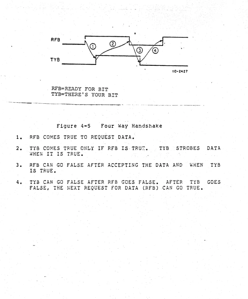
-2-The IMPll-B transmits and receives full duplex serial data from the IMP processor according to the "Report Number 1822" Four Way
Handshake. Serial bit data is assembled into 8 bit bytes in the
line termination module, and bytes are packed into 16 bit words
for transfer to and from PDPll memory. An important feature is
the IMP1I-B's ability to handle non-octet sized data buffers, and then passed as a 16 bit word from the KMCll to the PDPl1.
SPECIFICATIONS:
Mechanical:
Logic Mounting Space:
Panel Mounting Space:
Electrical:
Input Power: (Both Modules)
Cabling:
Environmental:
Operating Temperature:
Humidity:
Operational:
Transfer Mode:
2 adjacent Hex SPC slots in a
DDll-B,C,or D. When mounting in a
DDII-B or C, the Line Unit module
can reside in slot 1,2,3,or 4. The
KMCll module must be mounted in slots 2 or 3 only.
Cabinet Space 5 1/4" high x 19" wide. Cable access clearance must be made available to the rear of the panel.
+5 VDC @ 6 Amps -15 VDC @ .2 Amp +15 veD @ .1 Amp
A 10 foot cable between logic and the indicator/cable termination panel is supplied as well as all internal
cables. The local and distance IMP
Host Cable connectors for the IMPIl-B
cable end are supplied. The Customer
shall provide connectors for the Arpanet IMP side and assemble the desired length cable.
+10 to 40 degrees celsius
10 to 90%
IMP11-B ARPANET INTERFACE
-3-Unibus Load: 1 Bus load
Signaling: Bit asynchronous complies with
specification in the Bolt, Beranek, and Newman "Report Number 1822", Four Way Handshake, local or distant interface.
Data Rate: 330K bits/sec nominal, full duplex with
25 foot cable. Rate decreases as longer cable distance between IMPI1-B and IMP are implemented.
WHO CAN JOIN ARPANET?
ARPANET is a network of computer systems administered by the Advanced Resear< Government Department of Defense.
U.s. government agencies may request membership in ARPANET by
applying to: Director, Defense Communications Agency, 8th and S.
Courthouse road, Arlington, VA 22204. Non-US government
activites may also apply provided they are sponsored by a U.s. government activity.
INFORMATION AVAILABILITY:
Further information may be obtained from your nearest Digital Sales Office.
,'.
7 6 5 4 3
3
OJANtity • 'I.fU""tOW
, CIl8\.E. !CBS 1/0
_""u 'l.ta.lI"
...
_
....
.,.,~.
ItMlta.lllf' GUM'"
.
..r-
=
tLIII qlll'llf\ t::l
.
:,
.•.
~1
..
~I
f
~
!
f
~··:"""'t-:· :·.k~-::t·~;·~·:·j·h·;:;"~","'_'~"~"" ____ ~~'~;·i·~ft~·1a~'!ll1 A}
1-..:$x:. .. -....
-.-~-.-9.:
.. :::.:...--...
;;;;~::-:.:::.G:--+--I,~;INTENANCE
PLUGIII'''. St<"",';;O"HfI, "too.
bOr.QT!.C ... U ... \i hUT HIGHI" ~ ....
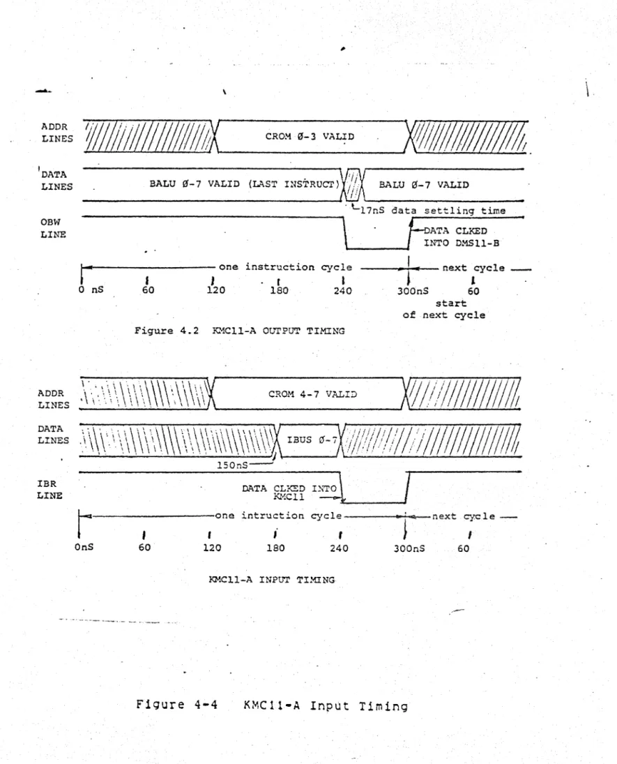
IMP DATA FORMAT
1 (1 - 32) 32
IMP11-B BYTES (8 BITS)
8 7 15
BYTE 1 BYTE 2 BYTE 3 BYTE 4
PDPl1 WORD 1 PDP11 WORD 2
STARTING BIT LAST BIT
7 G 5 4 3 2 1
TX BUF ~ Rl~
TX BUF 1 Rll
ENA
TX ERR TX CLR
LAST
BIT CLR STATUS
Rl2
Rl3 Rl4
RlS
HOST RX CLR ROY. STATUS RlG
GEl'
IMP Rl7
hURD
LINE UNIT DATA IN REGISTER
7 G 5 4 3 2 1 ~
Rll
ENA
r.rx
ERR TX CLRIAST
BIT CLR STATUS
Rl2
IMP RFN BUFFER
NOT IMPll EMPI'Y
. ROY 'RTT
-
Rl3RX BUF ~ Rl4
RX BUF 1 RlS _
HOST R.,,{
crn
lROY. STATUSI RlG
J;Mp· iENDOF DATA
LINE MSG. AVAIL. Rl7
SDL. -il
~~EA. AbA.
:H- (
(sF I)
seT
!lOR.
f7.1
C-wc..l
0
I
SMrus!\)t=,C;1t
~O(t-z..
leaF&.)
C)'T ft.Olt 171'1.tlcz.
0
, 'STATuST6O't
-l
(adel ;W~)BOFFER. I ....
"
SEt-o
S61..
2
-1---..,
S&c..i-~---~ S6L'
.... ....
"-.... ....
&DlJ\Dt:
S~L. t&.,
---
-Sbl. i\Dt.:
BOL.1l2.
B\lFF£R.
a,
wc:.,
g~'tI(
#2-wc.a.
51>1-
(SVFF££
D~pro~
L-)ST)
mamaomo
Technical Bulletin
Page 1 of 1
Product: DC349-AA Number: 4 Date: 04-0CT-1984
Author: Dave Stanley
Description: This bulletin pertains only to designs incorporating the Data Set
Change Register. Disregard if not using the Data Set Change Register.
1. Change in AC Specification Section
DL<7:0>
Set-up of valid DL<7:0> to the falling (leading) edge of DSI and DS2. tDSU (min)
=
OnsAll other AC parameters remain unaffected.
2. Addition to Data Set Change Summary Register description
To insure proper operation of the Data Set Change Summary Register, it is specified in the data sheet that programs should read and save a copy of its contents. The copy should then be written back to clear the bits that were se:. What the data sheet does not specify is that the write-back should follow the
read without intervening reads or writes to other registers in the chip. It i~
recommended that system interrupts be disabled before reading and writing the Data Set Change Summary Register so that the write-back can be guaranteed to follow the read without being interrupted.
d
d
d
d
d
d
d
•
•
t
I
I
9
I
a
•
•
t
I
I
9
I
a
•
•
t
I
I
9
I
a
•
•
t
I
I
9
I
a
•
•
t
I
I
9
I
a
•
•
t
I
I
9
I
a
•
•
t
I
I
9
I
a
IMPll-B
PDPll ARPANET INTERFACE
~r
,~1t'1tU1V
ropy
I~N'Y
r!nDu
digital
NOTEBOOK SECTION
OPTION N UM BER
2M-C078A-OO
DRAWING SET NUMBER
PROGRAM NUMBER
YM-Z078A STATIC YM-Z078B DYNAMIC
DOCUMENT NUMBER REVISION
YM-C078C-OO
DATE
-SEPTEMBER 1978
IMP11-B
PDP11 ARPANET INTERFACE
~"*,~rnpv
~"'b\l
~D·
0 0
Computer Special Systems
Copyright © 19i8 by Digital Equipment Corporation
The material in this manual is for. information3.1
purposes and is subject to change without notice.
Digital Equipment Corporationassulnes no
respon-sibility for any mors which may appel! in this
manual.
. Printed in U.s.A.
The following are trademarks of Digital Equipmenl
Corporation. Maynard. Massachusetts:
DEC DECCOMM DECsystem-l0 DECSY$TE.\{·:O
DEC:ape DECUS DIGITAL
~SSBUS
PDP
RSTS
ITPESET-8 TYPESET·It
TABLE OF CONTENTS 1 1.1 1.2 1.3 1.4
INTRODUCTION • • • • • • •
General Description • • • • •
.~
.
• • • •
• • •
•
•
•Operation . . . . Specifications • • • • Physical DescriPtion •
• • • • • • • • •
· '.
• • • • • • • • • • ••
•2 I~SlALLATION • • • • • • • • • • • • • • •
2.1 2.1.1 2.1. 2 2.1. 3 2.1.4 2.1.5 2.1.6 2.2 2.2.1 2.2.2 2.2.3 2.2.4 2.2.5 2.3 2.4 2.4.1 2.4.2 2.4.3 2.5
Site Considerations • • • • • • • Module Mounting Space • • • • • Panel Mounting Space • • • • • • Power For the Modules • • • • • Adequate Cooling • • • • • • • • NPR Jumper • • • • • • • • • • • Adequate Bus Loading • • • • • • Interconnections • • • • • • • • •
M8204 to M8240 • • • • • • • • •
M8240 to Indicator/Cable Panel •
Initial Power Up Check . . . IMP to IMPI1-B Connection • • • IMPI1-B Maintenance Plug • • • • Grounding • • • • • .. • • • • • • S«itch Setting . . . .
K~CI1-A Address Switches . . . .. KMCII-A Vector SwitChes • • • • Line Unit Driver/Receiver Select field Checkout Procedure • • • • •
• • • • • • • • • • • • • • • • • • • • • • • • • • • • • • • •
·
..
• • 3 3.1 3.2OPERATION AND PROGRAMMING • • • • • • • • •
3.2.1 3.3 3.3.1 3.3.1.1 3.3.1.2 3.3.1.3 3.3 .. 1.3.1 3.3.1.3.2 3.3.1.3.3 3.3.1.4 3.3.1.5 3.3.1.6 3.3.1.7 3.3.2 3.3.2.1 3.3.2.2 3.3.2.3 3.3.3 3.3.4 3.3.4.1 3.3.4.2 3.3.5 3.3.6 Controls/switches Indicator Panel
Indicators • • • •
• • • • • • • • • • • • • • • • • • • • System Operation • • • • • • • •
Com~and Structure • • • • • • INITIALIZATION Command • • LINE I~Ilialization Command CONTROL Ih Command • • • • •
SET/RESET HOS! READY • • • CLEAR READY LINE ERROR • •
REQUEST STATUS • • • • • •
BUfFER DESCRIPTOR IN Command BUfFER OUT Co:r,:i,and • • • • • BUffER DESCRIPTOR OUT Command CONTROL OUT Command • • • • Data Transfer Operat1ons • • •
Initialization Sequence • • Line Initialization Seauence Receive/Transmit Sequence •
• e. •
• • • • • • • • • • • • • • • • • • • • • • • • • • • • • • • • • • • • • • • • • • • • • • • • • • • • • • • • • Command Structure • • • • •
CSF Control • • • • • • • • Input Control Protocol • • Output Control Protocol • Buffer Descriptor List Entry
• • • •
• • • •
• • • •
Format Input Commands • • • • • • • • • • •
3.3.6.1 .. 3.3.6.2 3.3.6.3 3.3.6 • .4 3.3.6.4.1 3.3.6.4.2 3.3.6.4.3 3.3.6.5 3.3.7 3.3.7.1 3.3.7.2 3.3.7.3 '3.3.7.4 3.3.7.4.1' 3.3.7.4.2 3.3.7.4.3 3.3.8 3.3.8.1 3.3.8.2 3.3.8.3 3.3.9
INITIALIZATION Command • • • • • • • • • • • • • • Issuing Input Co~mands ~ • • • • • • • ~ • • • • • LINE INITlallzat·ion Command: . . . . CONTRdLIN Co6~and • • • • • • • • • • • • • • • •
SET/RESET HOST READY COMMAND • • • • • • • • • • STATUS REQUEST Command .~. • • • • • • • • • • • CLEAR READY LI~E ERBOR COffimand • • • • • • • • • BUFFER DESCRIPTOR IN Comffiand • • • • • • • • • • • Output Commands • • • • • • • • • • • • • • • • • •
Issuing an Output Command • • • • • • • • • • • • BUfFER OUTCoffiffiand • • • • • • • • • • • • • • • • BUFFER DESCRIPTOR OUT Command • • • • • • • • • • CONTROL OUT Co~mand • • • • • • • • • • • • • • •
RETUBNED STATUS • • • • • • • • • • • • • • • • IMP STATE TRANSITION • • • • • • • • • • • • • • LINE OVERFLOW DETECTED Command • • • • • • • • •
Dat~ Transfer Error Termination procedures • • • • • IMP NOT READY Termination • • • • • • • • • • • • NON-EXISTENT MEMORY Termination • • • • • • • • • Additional Information • • • • • • • • • • • • • • Loopback Mode • • • • • • • • • • • • • • • • • • •
4 4.1 4.1.1 4.2 4.2.1 4.3 4.4
THEORY,Of OPERATION • • • • • • • • • • • • • • • • • • • • General functional Description • • • • • • • • • • • • Indicator Panel • • • • • • • • • • • • • • • • • • KMCI1-A Micro Processor/NPR Handler • • • • • • • • • Line Unit Control Registers . . . • Line Unit M8240 • • • • • • • • • • • • • • • • • ' • • M8240 Driver And Receiver Logic • • • • • • • • • • •
5 5.1 5.2 5.3 A B
MAINTENANCE • • • • • • • • • • • • • • • • • • • • Maintenance Philosophy • • • • • • • • • • • • • Maintenance Plug • • • • • • • • • • • • • • • • Diagnostic Software • • • • • • • • • ~ • • • • SHIPPING LIST • • • • • • • • • • • • • • • • • • • • H'PI1-A CABLI~G • • • • • • • • • • •
•
• • • • • • •• • • • • • • • • • • • • • • • • •
C SAMPLE IMP 11-8 fIR!l.i'tARE LOAD ROUTIl~E • • • • • • • • • • •
Figures
1- 1
2- 2 . 3- 1 3- 2 3- 3 3- 4 3- 5 3- 6 3- 7 3- 8 3- 9 3-10 3-11 3-12 3-13 3-14·
I~PI1-B BloCK Diagram • • • • • • • • • • • • • • • •
. .
.
. . .
.
.
.
.
. .
.
.
.
~.
.
.
.
.
.
.
.
.
..
. .
IMPII-S Unibus Register Address For~at • • • • • Input Control Register - BSELO • • • • • • • • • Output Control Register - BSEL2 • • • • • • • • Buffer Descriptor List Entry Format • • • • • • System Initialization (BSEL1) • • • • • • • • • LINE INlT Command • • • • • • • • • • • • • • • SET/RESET HOST READY Command • • • • • • • • • • STATUS REQUEST Command • • • • • • • • • • • • • CLEAR READY LINE ERROR Command • • • • • • • • • BUfFER DESCRIPTOR IN Command Format • • • • • • BUFfER OUT Command • • • • • • • • • • • • • • • BUfFER DESCRIPTOR OUT Command • • • • • • • • ~
RETURNED STATUS Command • • • • • • • • • • • • IMP STATE TRANSITION Co~mand • • • • • • • • • •
."
.
.
CHAPTER 1
INTRODUCTION
1.1 GENERAL DESCRIPTION
TheIMPI1-B Interface, a second generation IMPI1-A interface,
:pro-vtiides a direct serial connection bet'.,;een a PDP11 computer
syst"e'rtj"'and t~e Interface l·~essage Processor (H.sP) used to conne,ct
Host computers to the Advanced Research Projects Agency (ARPA)
. network. This UNIBUS op~ion allows the user (with addition of
appropriate software) to communicate via the ARPA network with
other Host systems. The option has provisions for connecting to
the IMP's Local or Distant Host Interface.
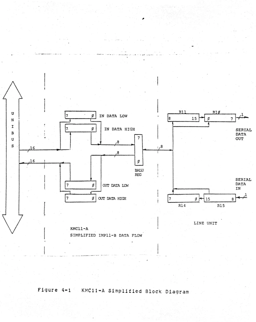
The IMPll-S is a microprocessor (KMC11-A) based seilal line unit
interface comprised of two hex modules (M8204 and M8240). The
t~o modules can be mounted in any t~o adjacent hex SPC slots
(example: middle two slots in a four slot DDI1-E) and are
connected by a short flat cable. The M8240 1s a line termination
unit module which contains the driver/receivers and shift
registers that connect to the IMP Host Interface. The M3204 is a
KMCI1-A microprocessor ~hich controls the M8240 and UNIBUS DMA
transfers. See figure 1-1.
<~.
~UNIB_US
- , )J_
PDPll CPU SYSTEM
rr--__
~__ _
-
-
-
-.,-,
I
I M8204
I lJ PROCESSOR
I
M8240 LINE UNIT
I
!.:f! ... ~
I
I I]>DII..:5 _ _ _ _ _ _ _ _ _ _
J
Figure 1-1
IMPII-B 810ckDiagram
r - - - ,
I LOCAL
I OR
"
DISTANT.
rHOST
I INTERFACE
I Il·lP
Page 1-2
1.2 OPERATlON
The IMPI1-H is controlled by a KMCIJ-A microprocessor. To initialize the unit, the PDP11 operating software must load the KMCII-A ~lth a set of suppliedfirm~are (microcode). Once this firmware is loaded and started, the KMCI1-A/M8240 line unit is operational.
The KMC11-A microprocessor executes from a lK writeable control store (firmware store) and lK byte data store. It controls both full duplex DMA UNIBUS transfers and a full duplex 8 bit data port to the M8240 line unit. The KMCI1-A moves data between the M8240 line unit and PDP!1 memory according to the word count (14 . bits) and bus address (18 bits - 128K range) set up· by the 4 user accessible KMCI1-A UNIBUS registers. Error handling and command information is also passed thru these registers. DMA block t ran s fer s can b e l 6 K (16 bit it' 0 r d s ) Ion g , h 6 ~; eV'~t
,
i t i s recommended that block transfers be limited to the "maximum IMP message length (8096 bits). 'Hlese blocks may be chained; up toB transmit and 8 receive bufter addresses may be stored by the KMCI1-A.
The M8240 line unit drives and receives full duplex data from the Host Interface. Data is received serially from the IMP processor according to the 1822 Report Four way Handshake and assembled into a 16 bit register. The 16 bit data Aord is presented to the KMCII-A data port as t~o eight bit bytes. Line status from the Host Interface 1s also passed to the KMC11-A via this data port. Data transmitted to the Host Interface 1s passed as two eight bit bytes to the M8240. The t~o bytes are serialized one at a time and transmitted to the Host Interface according to the 1822
Report Defined Four wa~ Handshake.
1.3 SPECIFICATIONS* a •. Mechanical
Mounting Space Prerequisite
Dimensions M8204 1>18240 Weight
b. Electrical Input Power
T~o adjacent hex SPC slots in an H960-DH expander bOX or BA11-K box
8.5 x 17.0 inches (HEX) 8.5 x 17.0 inches (HEX)
10 IbS. (Approx.)
+5VDC~5%
-15VDC.-t5%
+15VDC~5%
4.0 Amp 0.1 Amp 0.1 Amp
·
,M8240 +5VDC5%
-15VOC5\ +15VDC.t.5%
4.0 Amp
0.1
Amp0.'1 Amp
Power supplied by regulated system unit power supplies. Logic
c. Operational Transfer Mode UNIBUS "Load Data Rate**
Sl:Jnaling
TTL levels, .t.6VDC levels
full Duplex, NPR COMA)
One (KMCI1-A-ONE, M8240-None)
~o,OOO bits/sec nominal, full duplex (Dependent on IMP Host Interface)
Bit asynchronous - 1822 Report Four way Handshake
Page 1-3
Cabling Cable.terminator supplied Customer must supply - IMP Host Cable.
1.4 PHYSICAL DESCRIPTION
The IMP-B nardware as supplied consists of the following: 1. M8204 (KMCI1-A microprocessor)
2. M8240 (IMP Line Terminator Unit} 3. BCOBR-Ol (~8204 to M8240 Cable) 4. Inticator/Connector Cable
5. IMP - Host Cable Terminator
b. Interconnect Cable (M8240 to panel Cable)
TheIMPI1-B software as supplied will consists of the following: 1. M8204 Firmware
2. IMPI1-B Diagnostic
3. IMPI1-B (Host to IMP) Test Softwar~
j **Oata rate is ba.sedonlocal, interface (25 ,foot
rates will decrease over 19nger caoles wh~n
interface because. of cable delays.
CHAPTER 2 INSTALLATION
2.1 SITE CONSIDERATIONS
The IMPl1-& consists of two hex height modules, an indicator/cable panel, and four 1nterconnecting cables. The POP11 system must supply the following:
1. Mounting space for tw6 hex heiqht modules with UNIBUS access for the KMCI1-A module.
2. Mo~nting space for a 5 1/4 inch by 19 inch panel. Provision must be made to allow access to tne rear of the panel for cable insertion.
3~ Po~er for the modules.
4. Adequate cooling for the modules.
5." NOR jumper must be removed from" the slot that the KMC11-A resides. (Remove CAl to CB1)
6. Adequate Bus loading.
2.1.1 Module Mounting" Space
Page 2-2 2.1.2 Panel Module Space
The indicator/cable panel 1s a 5 1/4 by ~9 inch unit and can be mounted to tne rails of the standard H9bO cabinet. It should be mounted 1n tne same caoinet as the hex modules and close enough to tt',em so that the
a
foot BC06R-08cables can connect the panel to the Lioe Unit module (118240). Also, keep In mind that the indicators should be easily viewed by the operator~ Adequate space snould be provided behind the panel to allow the connect of the Line Unit caoles and the IMP cable.2.1.3 Power For The Modules (See Section 1.3)
The KMCII-A (MB204) derives its power from the SPC slot (~S, -15, and ground)..
The Line Unit (M8204) derives its power from the SPC slot (DD11-B, DOll-OF, or equivalent). It requires +SV, -15, and ground. The +SV is taken from pin A2 of ~ach slot (A, B, C, 0, E, f) anj the ground is brought on to the ~odUle from pin C2 of each slot (A, S, C, 0, E, f). The ~lSV is brought in only on pin B2 in slot C. If there is no -15V on pin C52, then -15V must be jumpered to this pin. Generally pin C82 is reserved for -15V. The -15V is used to provide po~er to the Line Unit·s distant logic.
NOTE
4
I. M8204 uP
2. M824Q LINE UNrr
3. BCOSR CAa.E
4. PANEL
.5. PANEL BEZEl.
6. 015T CABLE
7. DEVICE CABLE (TERM. SUP. 0t'lY)
7
6
2.1.4 Adequate Cooling
Generally adequate c~o11ng 1s provided in a POPIICPU box or in an expander box. Ensure that tnere is nothing blocKing the flow of air across the two modules. Consult you PDPll installation manual.
2.1.5 NPR Jumpter
The NPR Non Processar Request jumper (CAl to (81) must be removed
~hen the KMCI1-A 1s installed. The KMCll-A has logic that
arbitrates the NPR's on the UNIBUS.
2.1.6 Adequate Bus Loading
There must be room to add two UNIBUS loads onto the UNIBUS.
2.2 INTERCONNECTIONS 2.2.1 M8204 To M8240
The KMC11-A (M8204) is connected to the Line Unit (M8240) with a 1 foot BC08S-01, 40 pin flat cable. J4 of the M8240, located next to the handle approximately 3 1/2 inches from the bottom of the module, is connected to Jl of the M8204 module, Which has the S3me placement. The 8C08S-01 should ce folded over from one module to the other. See figure 2-2. This cable is used to line the KMCII-A to tne Line Unit.
Page 2-5
2.2.2 M8240 To Indicator/cable Panel
There are three cables used to connect the M8240 Line Unit module to the indicator/cable panel. Two of the cables, BC06R-08#s, are used to connect the IMP output connector to the driver/receivers
on the MB240 Line Unit Module. The third flat cable is used to
connect tne M8240 indicator drivers to the indicator panel. This cable also supplies the po~er to the panel.
2.2.3 Initial Po~er Up ChecK
Make sure there are no direct shorts of the power pins to ground.
If there are, remove the modules M8204 and isolate and remove the Shorting condition.
2.2.4 IMP To IMPII-B Connection
The IMP (Information Message Processor) is connected to the IMPII-B's indicator/cable panel with a customer supplied cable. There are two different cables; one supports the IMP's local interface (30 ft. max) and the other supports the IMP's distant interface (2000 f t . max.). Both cables plug into the same connector on tne IM?11-B although different pins are used. See Table 2-1 for cable pin out.
NOTE
Do not connect the IMP cable to the IMP11-B until the IMPII-B has been checked out with its maintenance plug.
2.2.5 IMPII-B Maintenance Plug
The maintenance plug for the IMPII-B is used to loop signals to the IMP back Into the IMPll-B. This allows the diagnostics to test out the IMPll-6 logic without an IMP connected.
2.3 GkOUNDING
Page 2-b
2.4 SwITCH SETTING
There are a number of s~ltches to set, in order 'to run the
IMPII-S.
2.4.1 KMCI1-A Address Switches
Ihe device address or UNIBUS address of the IMPll-S is d€termined by setting tne KMC11-A to the desired UNIBUS address. The possicle range of addresses that the KMCII-A can be aet to 15
760000 to 777770. However, the address should be limited to the
,floating address space 760010 to 764000 or the IMP-llA addresses
(772410 to 772430). Switches 1-10, located on Ell3 on the MS204,
1s used to set the address. The switches correspond to the
follo~ing address bits:
10
12
9
11
8
10
7 9
6
8
5
7
4
6
3 5
2 4
1
3 Address Bits
The s.itch in the off (open) pqsition produces a logical O'on the UNIbUS.
2.4.2 KMCI1-A Vector Switches
The base Vector address of the IMP11-B Is determined by setting the KMCII-A's Vector address swltch~s. The possible range of addresses is 000 to 770. However, these addresses should be limited to the floating Vector address range (300 to 770). The addresses 500 - 534 are reserved. The DIP S~ITCH located in E76 is used'to select the vector address. The s'~itches correspond to
the follo~ing address bits:
6 5 4 3
7 6 5
2
4
1
3
Switch #'5
Vector Address Bit
An off switch (open) corresponds to a logical 0 on the UNIBUS.
2.4.3 Line Unit Driver/Receiver Select
Page 2-7 2.5 FIELD CHECKOUT PROCEDURE
#
The filed checkout procedure requires the testing of the IMPII-B with the two dlagnostics (static and dynamic) and maintenance plug. follow the procedure below:
1 • Mount the modules and outlined 1n Section CBl is removed from resides.
panel in the available space as
2.1~ Make sure that jumper CAl to the SPC slot that. the KMCI1-A 2. Ensure that the power is supplied to the pins as
described in Section 2.1.3.
3. Install the caoling to the Indicator Panel and Line Unit module.
4. Set UP the KMC11-A to the desired address (address the
system software expects the IMPI1-B to have). If this information is not available, set up the KMC11-A for an address of 160110 (8) and a vector of 300. See KMCI1-A maintenance manual for the address set up.
5. Power up the system and run the following KMCI1-A stand alone di2gnostics:
MAINDEC-I1-DZKCA MAINDEC-I1-DZKCC MAINDEC-11-DZKCD
6. Having successfully run these three diagnostics, connect the KMCI1-A to tne line unit via the 8C08S-01 cable and install the maintenance plug to the indicator/caDle panel. Run the IMPI1-B static diagnostic error free. 7. Having run the static diagnostics error free, run the
dynamic diagnostic error free. Run the diagnostic in the local and distant modes by Switching S1.
CHAPTER 3
OPERATION AND PROGRAMMING
3.1 CONTROLS/SwITCHES
~
There are three sets of switcnes to set up for operation of the IMP11-B.
1. Device Address 2. vector Address
3. Line Unit Local/Distant Select
The Device Address is selected oy setting up tne switches in· DIP E113 on the M8204 KMC11-A module. The address range should De kept to the floating address space 760010 to 764000. See Section 2.4.1 for set uP.
The Vector Address is selected by setting up tne s~itChes on the DIP E76 on the M8204 module. The vector range should be limited to th~ floating vector space l300 to 770, excluding 500 to 534). See Section 2.4.2 for set up.
The Local/Distant select s~itCh is used to enable the driver/receiver logic to support local or distant operations. The IMP unit will nave eitner a local or distant Host intertace and the Line Unit must be set up to match this interface. S~itCh
S1 on the M8240 module selects local or distant mode operation. See Section 2.4.3 for switch settings.
3.2 INDICATOR PANEL
The LED indicator panel is used to·indicate the major status of
the IMP11-~ logic. It is useful in that it Cdn inaicate activity
Page 3-2
3.2.1 Indicators INDIChTOR
II~P LINE ERR
HOST RDY
. HtP RDY KMCll RUN TX BUFFER EMPTY TX RFN IMPII BIT TX TY
H1Pll B11
TX LAST
Ii~Pll BIT
RX DATA AVAIL
RX RFr~
IIO\P BIT RX1Y.
HtPl1 BIT
RX LAST'
H~P BIT
FUNCTION
Th1s indicator reflects the state of the IMP LINE ERR
FLop.
~hen this lightIs on, it records that the IMP ready line has be dropped.
This indicator indicates that the IMPll-S is one line, and that the IMPIl-S relay is energized.
This indicator is used to show that the IMP is on line.
This bit is used to indicate that the KMCll-A micro code is running.
This indicator sho~s that the Line Unit is able to accept a 16 Dit word
from the KMCI1-A.
This in~icator shows the state of the IMP's Eeady Eor ~ext ait line.
This indicator sho~s the state of the HlP 11~p f.;S:.\~he r es ,iour 5i t
line. . .
This indicator reflects the IMPI1-B's
~ast Bit line. This line is true
once during a 16 bit word and riot during every
Ib
bit word.This indicator indicates that the line unit has assembled a 16 bit word from
the IMP and 1s ready tor the KMCII-A to read.
This indicator indicates that the IMPII-S is ready to accept a bit tram the IMP. This indicator shows the state ~f the IMPII-S's There's Your Sit line.
3.3 3iSl~~ UP~kAII0N
Oper~ticn ot tne 1~Pl1-ri rricroP[oar~m is inlti~ted dnd directed
oy d dsel-prOdJcec ~rOGrd;r reSi()jll~ in tne :TIdin CPU ITlerr,oI'Y space.
Communlc~tion ~etAeen tne user pro~ram and the J~P11-B is
~rOVloe? cv a set at to~r cOGtrol ana siatus reqisters lCSR'sl,
~nic~ dre inteJrbl to tne K~C-ll mIcroprocessor. Tnese tour
16-cit reJlsters dIe. usee tor co~trbl input, status output, and
data i;,;"ljt df,'] outPJt. n)e tir;r.ware ~itflin the Ki'1C-l1
~iclocrocessor is SJ~~lic~ dnu supported bV Dle. No otller
v€r&ion 01 tne tirJ.Aare is supported.
·Ine t,o lo~ 'Dv~es in tne tirstt'o reqisters in this aroup nave a
fixed tor~~t a~a serve dS the co~wdnd heaaer tor tne secona two
re~isters. lGe secon~ t~o reqLsters form ~ t~o-~ord data port
Lor tne exChanoe of uni'.jue control/status co;nmanas between tile
1 ;..!? 11 -t.~ a il C) t.
r.
e use r pre:,; r a iT' • The con ten t. sot ttl e d a t d P 0 r t a r especliiej C'l dG iaentitication field in the command header.
Otner SL€citlC fields in tne t~o-~ord command header cpntrol
intelru~t efiaLlin~ ana set UP data transfers netween the main CPU
and tr.e F(f'11-3. 'fne seconct Dyc.e oitne first word is used to
cont3.ir. a sDeci3i co::;:.,aDC1 is.5uea OV the user proqram for i;;1cle",entlO'J ~.icroprocessor Stilrt., halt and initialization. Detailej descriotlons of eacn tlela in these four words are
presented In Sections 3.3.3 - 3.3.7.
;:, Jser :';'fi.n!O,f i5SJt2S:3 Co,f;i'dnO to tne I'-~Pll-b bY starin!] tf'e
CO';;;3t·:1 1"1 (,f,:; celtl.nent lS~·s. Tr~e La;11-i3 tnen intelPrets the
c 07 ::' :3 i i i " ; , 0 "' e r 1. 0 r :li s t L e s ~ e cit 1 e .1 act 1 0 n s • .3 j rd L:n 1 y , t t'l e
l·ltlJ"'~· iSSUe5 d cO:::~;6nci to t;;e user proora;r, tv storinq tne
CO,;'!.:),;,;; iii ti,e certlner,t CSi":;. d'1Q ilotifyinq trl€ user oroora'"!,
trl<:it ~ co,;~::~ano is 3v~ilar.d.e tor ret.rieval dnd e,xecJtion.
Mes~~~e d~t3 receivea or traDs~ittea cy tne 1~Pl1-t is Nritten
1 n t o o r rea (j frO;f, ~J s € r pr a :.:r a ": ass i ;.:j n eat; u f t e r s i Ii fl, din C H)
iFE""or .;. 11'.e l·c;'ll-d accesses tnese butfers tr;Iouot, l';on Processor
keou~sts (\~~J to a U~l~US aadres5. Au~lbUS B.ODzess is deflne0 as b n 1., - LIt 6 J ere 5 :;. 0 t t n {: ii, air:. C i-' lJ [t; e r;, 0 r Y 10 cat i en i. h i c n nus
oeer. leser--it.O for use LV an ;.Pf\ oe .... ice.
3.3.1 CC-:";i"i3na Structure
1 h e tc net Ion sot the s e ''; p n 1;\1~' 1 1 - b con r: roll s tat U SId a t a c 0 l' m3 n d s
are .:: esc r 1 t: t:? d i Ii t n e sec t ion s t! i d t f 0 11 0;, •
3.3.1.1 Ld1I,~.LIZ:.T1t..;:~ CG"r~;I;dna - lLe purpose ot tne sl:)qle bvte
l:ilIl:'iJ.l':"t'ilu,iCv~"l;:lijnd is to C1E-1r iill conalti.on S0nsltlVf: loqic 1n tr.t~··.C-l1 ,[dCrOUr cce:,sor aliO to iJlace tne prOCEssor III r.ne
Hu:. st,::ste. 1tlis CO,TI!TdflO (,'ust ce Issued ov tne user pt'Oqrdnl once
3.3.1.~ J.d.,.j;. L.tri~lizoticn Co;;:rr:and - 'Ihis comrr,ano
Is
used tolnitj~llze tne lineln eIther tne receive or transnlt direction.
A SEC5f3te CCffim~rc ffiust be issued for each direction. Tois
CO~i~ati ~ust De iss~eo oetore dnv ouffer Descriptor Lists ~ill be acceLte0 ov tne 1~PL1-c. It can also serve to reset the given
d 1 r e c t 1 C r;:; n Ii t 1 'Ii e a <.J r 1 Cl q ex E cut ion.
3 • 3 • l • 3 C ,J:: h, 0 L 1 ;'.. C () tun and - In e s eo COin man d S 03 r e i s sue d b v ' t n e
use r c r I) =4 r ci ~,; to for t e co ri t r 0 1 act ion by t n e 1 t:j P 1 1 -tj •
3.j.l.3.1 s~r/R~SEI HUSI k~ADl - Inis command is used to set or clear t~e nUSI k~ADf control OiE in the IMPI1-B. Tnis oit must DE set in oreef tor data transters to occur. Ine HOSI READ~ oit mav ce J,St,~ to siGnal tel€' otner sYstem trlat tne llwlrl1-b is readY
to btart 05t5 transfer. Ihe clearinq and resettinq of tnis bit
~ill be jetectea OY tne 1M? in tne node.
3.3.1.3.2 Ci .. E""R i'<Ei'.Di iJIIiE t:F?u~
-sets'.€:lE'Ier tne L·;P (loes not re3dy.
~EADY LINE ERROr is latched
It cat! only t'e reset by tr~e
USE r c r 0 :; r .:: :; • 1 I' e l: L t:,;";, l-~_ A D t L i ' t., I:: t<,k a K C ow rn d n G e l e drs t [; e
Rl::':'j,'l LL,t, t.1(i-·u/" ecr.lrol c i t if u',e 1:·~P IWi FEAul cOI!uitiqn i;i'ls
yOLe ="",'~'. j l l e 1,!;r:-il-O ;\iil nor. [(:5tart :ldta transfers as lonq
as tr,E ~i:..-".ji Ll·',t, r:.,Ki'U!"' elL is SEt.
3 • .:1.1. ~ • .)
r:,:.,,;:n:.:sr
SlA1J-S - ltilS co;r,r;\2md causes tnE l'>it-'ll-ci topass ~~c~ tGe current st~te of tDe co~munication control lines to the ~&er ~rCJr3~.
3.3.1.i b(JfttK Ct::,;:iCldPTU!( It. C00',rraoo - Ine user OfOqram issues tOis :c;,trol COlTiHdiid to ene 1:t:l1-B to assi'.n a ne':; nutfer
Oe5cric:cr .l.lst to tt:€:: desl'.:;r.'3Ceo oireetion (receive or
traj~s·:iLJ. /-. 3UfFt.~ l·t.6C1-nt:l~)~ Ii, con;rr,,:lncl points to and oetines onli CGe ~ser oetln~d l i s t , ~na t~is commana must ce reoeated tor
e~cn 11SL Udssea to tne i~Pll-b. IDe user p[oqraIT can assiqn a
il',ad rJ or (>\0 lists lil edcn dlrE:ction. The CO!l.fl,afio contdlns tne
startlna llSt adores~, expresseo as an 18 oit Unibus adaress.
3 • 3. 1 • S t: J f f
c.
~ 0<': 1 C OU: a r; d '"' I [; E l:W 1 1 - B iss u e s tr d s con t r 0 1CO::r::lr:.:: to tne iJser ~r,·}.~r,,;;·,~r:en Ulf:: cutterassi,qr.€'c to a receive
o~ercHion .J.S terrllndte,j~ l,cnerdllv. d receiVE outtE"I is ter,:,lrdte,,;snen tne Ju1fer is (Jll (bvte count: zero). Hle
con,,:, a n::! cur; t din s tr 1 e 1 3 -t;. i t IJ th S 1 cal d d d r t: s sot ttl e en try i n t ti e
Sutfer LiescrlPtor t l s t . H : e reason for t-errninat.lon is expresseq
as ~ si~nea oct~l Duncer -12B - .12/. Neqative values represent
fail~re to t~r~inate tne &utfer successfully.
J . j . i . c oLr~E~ D~SCM1~rLk aUI Co~mand - Tne IMPll-b issues this
C 0 [" t r ;; 1 C (I .~ .. -:- :3 n:J t o t r, C (j S e r pro 0 r a iT, Ii t j e naB u f fer C esc rip tor Lis t
assl'J;ie:; to Eitner receive or transmit is terr:inated. Tne
co:::r,=,'id COi,L61flS trie 16-oit onvsicdl startino clueress of the
BUIter ~e5cr1rtor Llst. )ne reasen for termination is expressed
a 5 -:. 5 i .;., EJ 0 C t 'J 1 n ~ (" C e r - 1 L.~ .. t 1 i. 7 • Ii e q d t i v e val \.i e 5 r e 1=' res e n t f all u r e to t e :,', ina t e t L e ~ u t: t e r e esc r 1 P tor List S u C c e 5 stu 11 ~' •
3 .. 3.t.7 ((j;id}L LlLil CO~'ir:and" ine L1Pll-b issues cne of tnese
CO:;·:T.:Hl.:iS to tne TaH, Cf-'j .H,eo i t eetects a transirit or receive
error, or cn re~uest cv tne C?U.
3.3.2 cata transfer Uperatlons
For trJe !-;-.lrooses ot tnis svste,fi overvie,\,
reCel'ie ,)03.ca COT:1,":!fl'J seGuences descrioeo
~ener~l 3~C 3re ~eant to serve 55 oaCk~round t:rtS~~".l?tl(';,.:i in tr:E: ClloLter.s tL::lt tOllo'.'. •
the transmit and
in lnis section are
for the aetajled
.3 • j • L • 1 ! ( 1 :. Lj 11 7 a t i 0 :. ~~. e u u e r; c e - Aft e r t L e 1 "T 1 1 -t: :r i c r 0 r; r () (H d [n
i s 1 (i:; :) E:.] , t : i e r 1 r s t::i ;: tIC r: t:3 ~ (7.' ; ; r; 'y' t fl e use r pro q r a l, 1 S t 0 iss J e ar, 1.1. i ;. .... ;~iL"'ILj, co:,~~;.::; I"lien ~'El forms a A,~TLP CtU'i~ on c':e {" C-li"lcr:)CrOCESscr eli,,; (ndce::, c;e crocessor in tne pun stdte.
i\ i ttl t 'i i S :5 C tic nco .1'~: 1 e t "" t r. e l',~· 11 -t:' i s rea 0 v to ace e ~ t the
t lIst ;: {) :. >'t!, :J f r C.f t n E:: ;.; S e r •
3.3.t'.i iJi;;c lrYiti:l1L:3.tio;'1 "f-lUenCe - Hie user iss J t: ;) t, e L .i. : ; t I f, 1 l e o ' ;; d n <J tor e 3 C [) a 1 I' e c t ion I r. e C C~~ r :HL.l t:: n a c 1 e s t n c. 1 i j, e
recettion.
tor SUDSeQUent
rr u s t to r'e activateo.
t.rans:lisslon or
1.3.L.3 ~ecelvef[rarIS~lt Seauence - Gnce the user proqra~ has
inlLi,}iiz.t;:G tne lH;e tnro\.l;:jt! Lldt. ltdJ comrnanas, UH:: l'd?-llt,-) 1S
r e? I) \ to::., f' r t 01.[1 a I' e c € i \; e () r t r a r S iI' i t a a tao Per d t 1 0 n •
4n 3Ct~il r0ceotlon or tr6ns 15510n is initidted {ner toe user
p r o:.aj :- 1 S ~ '.J e s a ti u F r t k D I:. S (: r H I U t\ 1;< c 0 rr rr. and. ,\ ti e n ;'i but t. e r 1 S
as;;, 1 ..; ;; EJ , it. i 5.1 e s L,; : id t t;',1 tor t: 1. t fi e r reception or t ran S in iss ion •
trarlsfeT t€rrrEI-3tion C)' lS5Uin'l 3 bUfFl:.,R Gul command. The
1;1!- - 1 I i: t e r " ina t e s a n 0 r ,." 1 0 ~ t a t ran s t e r 0 per a t ion for 0 n e 0 f
t~o I~]~O~~: tne G~tfer aeSlo~ated bY tne last butfer Descriptor
Lis t e ;, t r V 0 a 5 De (:> n t 1 11 e cj () r d n b n 0-0 t - )\, e S 5 doe 5 e a U e n c e h q S [) e e n
oetEcte~. It a r~ce~tio~ error i5 aetec~ea, tne l~P-llH infor~s
t~ie u,s-2r Groor:l'T at tne {'rror oy iSSuinQ d blJfri:.F< UUl command
co:.t,:;irdLJ tnf: CO:H:: oesl'~r":1t.lna tne error cOfloition.
ILe 1 ~~l1-c intor::s tfie ... ser proqrarr. of a normal completion of r;:otr. tr,~r;s.rlt ::If;.:! Ieeei'';€: t)utter Descriptor Lists tv issunq a i5 !...-t f 1:.? \. r ,) C I' H i CJ ~ U 1.1 1 COr': .;, a r, <1 • J f c e r t a i n 1 i r: e € I r 0 r s are
\.Jettctc), t.ilE' l;.'Fll-i; returns tetE aftecteej butter DescriPtor ListS :.:.; i;55",in'l burt-Sf! LH:SCid PH)~l. UUT COlon1anc.s containinq tIle
C;) 0 e :J e ,5 i ;:;; Jd t I n ~ t r, e err 0 r c () fl1 i t 1 0 n •
3.3.3 CG~~a~Q Structure
~s ~r~vlo~slv sno,o, tne IMP-l1ri 1S an NPR device residinq on a
i'L:?-.i 1 : .. J31t:l;,'). CC!1fc·;rlicatlorl oet ... een the mail'" CPU-resiaent user
prYH6' ~{r;;J tlie l':l:~-llb 1S accor;'Dlisrlea tnrou<:jc, a set of four 1 c -;: 1 t u: I 1 G U ~ Con tr 0 1 all <l .':i {; -3 t ;] S r e q is t e r s ( C SF: • S ) • '( r, e e i q r, t
Oy te sec:,;; r 1511"1-.1 tnese fau r r E-(~ i ster s are ass lODed t ne to 11 001,' inq
3 ' G res s '" S F' t r. e 1/ U Cd J.€ t 10 d 1:. i n~ ad", res s s ~ ace: 7 b X x xC,
j v ..; ." ; ;, i ,=. f ~, A L f j t) !. x; x 3, i t X A). ~ f 7 (' X X X ~. lox x X (). a !l a 7 Q X X x 7 ,~ 1 t n
t (j E: '" i J - , :J;..J :i (; ,:; r ~: 5 5 esC) e i r; '-I t Ii f: f 0 J r e \/ e n -I. u ;" t ere ci 10 C "3 t i 0 f' S •
I n , .J1 t 1);, .:'!11. tour i ) ' loUiS C.:3)--· s are u0tn (ytE: <l!",:] ,'<oro
2:': Q n, ';3 ::;;,: l. E: • .'Ii t :-•. 1 iJ t :d= COL C e (; t () t f.1 a a t i fi 0 U 'd t< USa (J eH E: S ::; e ::; I
J. Co t. f' 1 S . .: A > .i. :1 '1 :i t 0 r 'j r, ":l r rat 1 'y e , t ri e lj - n y t;. e a jar e sse s
jesl~~ite~ hS~L~ tnrCJch bS~L7 ana the 4-~ora aocresses,
SiL~. 3'L~, and ~~Lo. Inc Gyte ane tull-~oru tor~ats tur
ale
St.:;Ll',
U',e
1 ;." ~ 1 j ... C L j . l c ~ vee, r~' ' 5, Las e ~1 0 n ·c r-~ e s e 0 e s i q n (3 t ion s, are s u :~li;-;; a r i zed
in t 1 : ; j r e j - 1. 1 t. e s e::, j j r 2 S 5 ref ere n c e S,d S des i j n alE (1 i fl r 1 q u r e
j - 1 , " I ! t: (.', e G d 5 1 S f 0 [ i.. 0J' d J:H e 5 5 1 a e n r i t 1 cat i c n in t r, e
to 11 Co .'.1 ;,:; Get d 11 t:' (J C esc r 1 [.. t ion s o t t LeI r: P 11 - b con if. d nos.
oS 1 :--c c c;: f: 1· ~' 1 1 -;-) 1 S ::: oj S 1 C d 1 1 ~ 2 n ll .. D (j t -0 u t P II tOE V 1 C e, 1 t i u 1i 0 ,.: 5
t r,d t ( ;', e CO ;c; -3:i . .J set t 0 r t r, 1 S (l e v J. c e c d n be cat e q 0 r i z e (1 d S i fi P 11 t COf':;-',ji::iS or::: out~.ut CO:-:-::-::HJ..:;S • • :.'" opcosea to recf::5.vea al,d
tI6nSilr..tf·C o3ta, in;;",t COT,i'aLas are COln;(ldnas issued to tne
i·',::. I l-r-: Cv tr,e ~',,:dn Cfiu, (.;uU)ut CO,,;.:aDOS are Ulose isso€a to tr;e
rr~aH. C~,j L:y tne l't-'il-h. Ii'.e strdcture one) tor;nat of t.ne HiPll-b .i n ~ -J t ::l T~J .) J t::.~ d t. co 1; iT :-Hl C S : H .fi' d € S C r i [; e din Sec t ion S 2. 4 ana '2 • :,
f 1 f-lU r e j-1 li·'~ll-t Unious t<.eqister Address r orrnat
15 8 7
BSELI BSEL~ SEL~
,-BSEL3 BSEL2 SEL2
BSEL5 BSEL4 SEL4
.
BSEL7 BSEL6 SEL6
3.).~ CSri Control
foe i~?ll-H is the co~truller of the CS~·s and the fDP-li user
orc~r3~ 1S only to read or Hrite into toe cata ~ort ~~en
oerTitte~ Cy tne I~?11-b. A protocol must be adherea to oy [De
'user oro~rarr: i t i t is to suCCessfJllv iSSue Cor[,rnancs ar:cJ receive
CO[(,:Tdl:·JS t r Oi11 the 1 ine un! t . bSiLO is tne i DC U t cent r 01
reqister. b:)t:L2 15 tDe Odt~t;t control reqister. [ne tONO
transrer directions nave been split into different reo1sters to
a vel Ci rae e C 0 Ii ,) i t ion s a ;-, d S lj b seq u e n t d a t a l 0 S S • H 0 " eve r t n ere i s
still a ~OSSlbilit~ at the interrupt ena~le bit oeino clearec or reset ::1 J r 1 n ~ C e r t din I fl. i c r as e con ON in do." s •
3.3.~.1 lnput Control ?rctocol
-FIlJre 3-~ Input Control Re~ister - bSEL0
7 6 - 5 4 3 2
,
-I I
ROYI lEI RQ~ UNUSED I/O CO~~L;?:-1D TYPE
I/U
RDil
l~i
OQ - liUfrE~, ~~~(~lPTU~ iN
vi - CGhi;;:uL Ii.
1 1 - L it. i:.. 1 i d I
Directlon of oata tr6nster - reQuired only on
B0fh:,tt lJESCF,If'HiK iii ano i..l;.E. 1;.11 commanos
tv = tI.aLS'i.lt 1 = receive)
~eq~est Input ~lt ~Jst oe set o¥ the user
proqrdn tL reG~est control of tne 5 data port
o 'y t e s ( c S Lt . .! 3 - t<:l :,1.. 7 ) . ; u r t.. : Cor t r 0 1 i 5 not
act~cillY ltdnteJ u~til HDil IS set cv the
~J /' p 1 1 - [, •
lIllS elt -:ust ce clear eo after aSr~L3-2SEL7
::ire 10.:l,,€rj to trlG·:Jer tne 1;';i-il-6 to acce()t
toe co:;;;,a:-.:.)
~nen set GY the 1~?11·~1 indicates
pr aOrciTe f,3S control of 3S£i..3-oSEL7
the user
lnp~t InterIuct ~nacle - ~hen set oy the user
~rOqrd~ ldt tGe sa~e ti~e ~Ol 15 setl, will
Cd us e [r;e L'P Il-b to oene r ate ,an inte Ir uot
vectorl~; at Ax0 ~nEn i t sets ~GYl
itl€? tOltl;,jt uf tr'lE lr-:~,;Jt Cc~';tr'ol ~·-E:;:;ister is ~i· .. ·t:·n 1~; Fi:Jure
3-L. In U[Jer to ~dSS a CO~~3~~ to tC,E i ~ll-c tnE user i) - l o t c n E; 1 !; 1."; iJ t
L,1id:., l , d ! c:or.'iar~cs,
3150 0€ soecitiea.
i,Jn(J[tc'o.
(o~tlol rEJister.
ir; 6its
l' or tf,~ ;::vF r i:.~. 1 i. ano
tra~5ferrea ffiGst
1-\ t [n 1. S (lO i ,. t t r 1 e USE: r "". <.: s t 5 e t t t. e ;:: e ,::; u € s t: 1;- ;:: 0 t e l t ( cit S
- h'vl 1) t. 0 r E:' c. II est COL t r 0 l o t t r. '= 5 :: c t. a ,:; crt C y t € S, b::' t:. L 3 - 7 •
l t; e I '.~ P 1 1 - d I. i 11 res L c r:·~ t c t I, e S E ': t L,,,; 0 t t~ \.: 1 L.·y '3 sse r t 1 r -l hIlL 1 I { L 1 C n '.:J 1 V t 5 eel, t r (. 1 e f t [" e ,:; a t d ;::. crt. 5 t c t i) e J s e r
i:n O::,J r d~' • iJ n t 1 1 1<;~ 1 I is SEt t I :e': 5 E r C~ ;H' 0 t "r 1 t e l r. t c tr. e
J~ t a /:.; 0 r t. s ... i t flO 'It t r e ~. ({ 5 ::; i L i l. l t·: etc 0 r r IJ C t 1 (; 7, • r [; e lj s e r
h~s tAO dlternatlves 6tter settlno ~~l, eltrer cc~tinuallY
o r f., ~' rio) i C d 1 1 i r. e 5 tiL":: t G r ;. i.; 1 1 ;;, e t :::; r set t i r: J 1 n ~; u t
lnterruct i::o<;ltde (it_I) .. It.:, h , i . If Interr'.J;::it c;:.::.::::le IS set
t n e 1 l'l F 1 1 -b .,\ 111 0) e r. Era ted n 1 n t e r Z J L· t vee tor 1 n;.; a t .\ j.. v "n e n
I t sets POll.
On detEction 01 k011 t~e user crOGr~~ s~cul~ ~rite .all
releVd~( Intol~atlon i~tG the ~dtd corts. Care ~ust ce
t3ken to cled[ all 0n~s~c oytrs as these corts are not
c 1 e Cl I e (J () Y t f) e 1.< i' 11 -r::: d [ 1 S i: J 1 i 0 115 reS u 1 t s "c" 0 cell r •
',il e n t Lee o;n:T d n d 15 C C:; ;., 1 e t e t Leu s e r pre G r a:t C i e drs I--0 1 I
tne input control reGister or any data port until the
I~~ll-~ aroes ~Uil •
.. f:en r<uiI lS :jro~ced tI,e inc-llt cycle is con,clete and. tne
... se::! caD inltlcite anotner lCOUC command.
3.3.4.~ ~i~ll:C;jt Control iIrotocol -rioure 3-j
7 6
RDYO rEO
1/0
Uutcut Contrel keqister - bSELi
5 4
.,
-' 2I
RQO UNUSED .I/O
l
00 - BL~FER D~SCRIPTUR
our
v 1 - Cui'ilfOL eu r
10 - bvff Eh OuT
1 fA
I
CO !v1.11Jl.ND TYPE
,
Direction ot transter, if applicable
II
=
trans~it; 0=
receive)oS e t b V t n e L\ P 1 1 -c t 0 ina i cat e i t n d s i s sue Q
an o~tc~t command in the CSR's.fnis cit
must oe clearec bV tne user proqram to
i~dicate it is aone ~ith tne CSR intormatlon.
Gutcut Interruot Enaele -. if ceen set oy the user oroqram,
~JiU cy the l~?ll-b will
interiu~t ~ectorin~ at AX~
this oit has tDe settina ot qenerate an
f r, e tOr:r..H 0 t t:-. e Gut c .... teo n t r c 1 R e cis t e r is a i ve n in f i q u r e
3-3. ~nen t~e l~Pll-b issues an out~ut co~mano i t hill set
tne CC~~dna ty~e in ti~s 0-1 of BS2L2. elt 2 retlects tne
cirection of j d t a transfer if reouirea by the command. kDtD
loit 7) ~ill ~e set co~c~rrentlY. If output interruot
endcle is set, t~e 1~P-115 ~ill oenerate an interruct
vectorin~ a~ AA~.
en
aEt~ction Ot ;0iO tne user orooram can take ~ndtevercictlon 15 reQGlrea out xust inaicate the completion of tne
3.3.~ butter Descriptor List ~ntrY format
All Duffer intormation 15 passed to tne lMPll-~ In the form of butter DescrlPtor Lists. tach list consists of an ocen-enaej seri~s of entries dS ~efine~
In
fiGure 3-~.i' i Q U r e 3 - .. ti U f fer 0 esc riD tor LIs t En try f 0 fiTi at
lS
I I I
BtrFFE..'=t ADDRESS
SA SA
N+2 !r;.ECM 17 16
t
j
-.N+4 WORD COUNT
.
I
•I
! !,
,,
! •I
,
STATUS ! UJ ON I TR:o .... 'IS11!': ) ! !I
. ·N+6
,J
6U~~~~ AUu~ESS dies 0-15 of the 18-cit physical aadress
of toe start ot Duffer
'd2
fj~lb, brll7 bits Ib-17 of the 18-cit ~hysical aaoress of the start of butter
Lo~ical end of messaqe occurs at the end
of tnis DJffer (yes
=
1; no=
0).
l.-the lenqtn of toe bufter in 16-bit Nords (odd byte is rounded U,:J to tlle next full .... ord)
STAI'uS
cleared D\I'
Termination status of transfer (s~oula be user ~roara~ cetore cassinq on list to tne
VALliE
1 Buffer word count reached zero
'.J
2 -4 -5
Receive EOM aetected REAuY LI~E ERROR
Non-existent memorY location
lneldst entry in tne Butfer DescriPtor List must oe
follo~eo oy tne I1st terminator ~nicn Is a ~ord containinq a
-1- in EHt
o.
3.3.6 Input Commands
As previously descriced, the I~P-1IB executes four for~s of inDut commands, ~hicn are listed belo~ in the qeneral order of user proqram issuance:
1. LdTIALZATION
2. LIN~ INITIALIZATION
3. CONTROL IN
4. BUffER DESCRIPTOR IN
AS a aeneral rule for inout commands. the user orocram must
execute tne PD?-11 instruction 81SB to store oatain BSELO
and 8SEL2. a MOV to store data in SEL4 and SELb, and a MOVS to store data in BSEL3, BSEL4, BSEL6, and 8SEL7.
rhe format and field descriPtions for each co~mand ~re
detailed in the following paraarachs. Some tvpical examoles
0·£ PDP-11 instructions and instruction secuences are included to demonstrate the user-proaram commana-1S5uina process. rhese examples are oresented for explanation onlv and do not implY a sinaLe metnoa of implementation.
3.3.6.1 INITIALIZATION Command
-Fioure 3-5 System InitializationCBSEL1)
---'-~~-,
15
-
14
8f
,
I f IRUN MCLR ..
I I I t t
HUN ~hen set, RUN allo~s the KMC clock to run and
therefore execute tne firm~are.
i-1ASTER CLE..t'H- - "hen set, In1 t 1 ali zes botn (tie
1'\ • .1C and line unit ana stops ti'H~RNCC lock
l~lllALl~ATlON is the tlrst command issued tiy a user Droaram
dt· start.up tiwe, to initlalize ttle t-::-lC-llrnicrcr;rocessor ana
pldce the unit 1n the run state. The tormat of tne
l!JIl"lALIL.hI'lON CO;M:,.:iflO is silo· ... nin rlQUrc 3-5.
Initializin:.;J ttle K"lC-11 microcrocessor tv tt.e user proaraf!'.
is t10ne 10 t. ... o steps. F1l"st the ~laster CIEe:r tit is set
iolloNed ov settln~ of t~e ~un bit. Atter settina the ~un
Dit. tne user pro~r~m ITU&t ~~it tor l~S oefore ac~essinQ aGe
of tt'le CO!iI'nana ne~ucr s b~t.,LO or b5£Li. Ite recomrr,endec
metnod tor settin~ the ~aster Clear and ~un bits, and at tne ScH:e ti,1:e lrr.olen,entll:Q tile reqUired aelay is to write a
non-zero value into b~tL2 dnd walt fo~ the I~F-llb to clear
toe eyte oefore proceedina. for exa~cle:
hOy'
I'lUVt.\
t·\U";
A: 1518
b\j~
13k
#40000,SSLU
;,377.H51.L2 r; 100000, Sf_Lv SSr.;L2
;.
JS~T MASTER CLEAf bIT
: •• RI IE r.(L~-Zi:.RO \i f:.LUr.; Ilj ESEL2
; Sl::I RU; .. bl1
;CLEARE0 fE..T?
; 1',0
;tES, PROCEED 10
e
~liice Ule Haster (ledr cit is not self-cle6rin'J, a
move insteaa of a oit set lnstructio~ is reqUired to
clear tfie n:aster clear c i t dno set the t'un t i t .
IhesE.: dctlons set tr't: f.lth cit ~locino tr;e Hif-l1-b in tne
ocerdtion31 state. At tOiS point, the user ~roaram can
t; e q 1 n set tin·'J UP t 1"1 e 1,·1 r 11 ... b tor Sue 5 e c I..l e n t o p e r i:l t. ion 5 •
S f< L U H 1 t s ri t
r.
r cue n 1 3 are (j e s i ,J;"l d t e G fl· a i Ii tE:n an c e cit s •Til e 5 e b 1 t 5 a leu s
eo
t v loa D l[hl, IT; a HI ten a r, c e a L d a i a 'J nos t 1 Croutll,es aoo hdve ne ettect on nor:nal HPll-t! c:::eration.
j.3.o.~ Issuinq Incut Cow~ands - All input cc~mands otoer
th30 lklTlALlZr.; are lssuea by a user prc~ram in t~o
s~ccesslve steps. In qen~rdl, the first stec involves a
r e 'J U est tor per 'TI iss 10 n t 0 iss i.l e an i n put co:r m 3 n dan d a
response bv toe IMFll-h tnat it is reaav to accept toe
CO·\1f1,dno. Altnouqn tne 0ro'HduminQ se(Juences tor tt.E' first
steD dre (l€ScrlCE''l tOI tnE' Ll .• t. 11,i£ co:rfT:ar.o, tr;ev also
Jl,jolv to the CL\ltd.iL IN dna buFfER DESCRlf-1Cf.' l:~ COHirnands.
Ine seauence for tne second step lnvolves comclet1nQ the
con;man:J bY lOdoinq hSe.L.>. ::;r~L4, and SE.Lb .'/lith tne aata
aitterent tor each co~nand.
,',itrl U,e E:xc€ction ot tne first LIfH:': IN!!' conliTana issued at
Sl~rt0L ti~e, tne ~5er DIOGram must cneck that the HOYI bit
n ':i 5 DE' e" c 1 e "H e 0 0 r lor t 0 1 S sui n q t r. e n ext i n put COif: fl: d n d
( i II C LLll;"'i ::; t n e sec 0 n O d II 0 5 U os e que n t L I '" t. LH Teo m· man 0 s ) ..
[ '1 e L , j 11 -:; c 1 E:d r s 1< f) i I t o 5 i '-l n a 1 to a t tile 1 a 5 t 1 n P II t
COc,>::tl;C lSSUC"O IdS Leer! corr:Cdeteo. \',oen clearinq PCn:l, the
l'~li-~ ~lso cle~rs all ot~er Olts in bSELO exce~t the lEI
Olt. ~n instr~ction sequence to test toe HD)l bit can taKe
t roe t C r .~.
: r [; i l S 11 L LS E T
;CL~AR~D-lSSuE COMMAND
Si~ce the 1~211-b does not cleaI bSt.L3, SEL4, or
~t:Lc. tne Jser irust er~sure tnat tnese reoisters are cledreo cv executlDo aPDro~riate clear instructions
crIor to iSSJIL.J a COl:r~no or bv issuin':;j Ule cOinT-and
"itt. "iiJ'" or i;;Witt. inst.ructions.
" 1 t;1 t r.!::' :. ~; 1 1 (0 i t e l E ::. reI), t r. E i fl i tid 1 t aSK t o e e per fer ;" e Q
t· 'j tr e J S E: r i s t c set tr e C 0 fV!l a n a i rJ €; t; t i t V t j e 1 (J (i n (r; i s
E " "':- ,. ie, :: St. L ; j to 1 t s \.,' ·3 i' Cl 1 = 1) , t n e f-iJ 1 (. 1 t , a r: Cl 1 : r; e c: € S ;; ·5 [ V tr, e H I G i t . ., 1 t n t n e i-< (J r L 1 t S E: t , ( (-I e l; 5 e r ;::: r ::; ~ r d ';' r; r .. S t t L e L "a i t f Co r t :. e 1 ,-, F 1 1 - b t 0 S E: t f-' [:). .i. •
~.::\ t.i15 ;:,re:cej.iIE 1:;; cro~:1Td:ped aeDefl05 or, 1,r.eU:er tr.e s t ;;., t e - l, r ( r j e 1 ~. 1. t: i t e ;-1 ;~ t; 1 e s i f, t err UP t. s. I n e 1 ate rev
oet~E:en lne ~ser ~r0Jra~ SEttl~Q tne POI oit 6na tDe 1~Pl1-~
reS~O,j:i:;.ri~i ';.)1 SE:ttlr-] rDtl can ranGe troi~ a rciniin,;:; ot L lJS
t C : i :L .. l',;j Tot ) ::. S .- .'.T E: n u 51 fl:./ t f. e 11:..1 D i t , t n e \; s e r La s
t~reE dltern~tlves:
1. ~et tne l~l cit to en~ole interrupts. As a conseuup~ce,
U:t;' 1·211-2 lr.terructs tne ,fain CPu Anen i t sets tf;e
I'
, i 1 1 0 U:. • 1 ;, e -~. l-C'" - 11 ins t rue t ion i it,,, 1 er. e !l tin Q U-l i salternative Cdn ~dve tne form
iuvB :113,tS~L0 ;S~l BOI. lSI, A~D INIT fA CU~~
,\ n e Ii i r. t err u u t t: d t fl e use r pro (1£ d;;1 Cd n pro c e e a d ire c t 1 y to lead S~EL3. S~L4. and SELo ~itn tne app[ooriate data.
2. Lt.'2iVe t;~2 I d oit clearE';] ana cheCK tn€ state of Ule
~~Jl ~it c; settinq a tlmer ana
(eltor~i~u 3 CGntln~ows test 1000. t L .::, t s e ~w e 1\ C e r· ":! s e G \) n :3 t i iH:; r i 5,
r.,1erfOrrT'ln(J d test or
A ;P~iI S[l, LOAD CUM~A~O
bPI
bP b ; hey 1 1.1,,)1 ,SET, f\t;SET T ltf,l:,P AND
;ktS0~E PRIUR TASK AT H. ~HEN TIMER
;GOlS Lff R~lNT~k AT C.
It a oit test loop 1S r~quired, the seauence tor~ is
1:.: 15fb bSi:.LC)
bi'L t. ;I-!Lnl :.01 SLT, BkANCii 10 1:, A~W 'lEST
: AGA 1:'1
;~Uil SEI, GU 10 D AND LOAD CUMMA~O
.3 • l) 51 n:.:l t his :3 1 t ern a. t i ve, ttl e use r pro q r d m c 1 ear S 1 E I ( it
SEt ov tne prior co~~ana), sets ~Ol, and tnen performs
t!. e . t!;) use k. e e ::;. 1 n ::; ass OC 1 ate a 'I. i t n iss u i n q t [1 e cur r e n t
cO"·ITand. hltr; tLe flO'JsekeeDino done, tn€ user proqrarr, C[;t2CKS huil. i t rl;d is set, tne user praGIan. completes toe co~~an~ iSSUInQ orocess. If not set, the user
prcora~ sets lEI ana reSJm~s a prior taSK ~nile awaitinq
~n interr0Pt on RD~l set.
l~e dOV3nC3~e of thIS alternative is tnat
UVErn€:ij is sutst3T!tiall\/ reduced since
~S0allV SEts ~~il hltnlD a few micr~5econds
~Ser ~ro~r~ sets ~01.rne form of the ;:, e:.. ~; e :: C e i: 0 r t n i sa;", ~ r v a c n I S
:::. 1 L ::'; • 1 t};J , to. S t~ L u :CLE~\h IF~l
interrur,t tht: HlPll-B
atter the
il"'str Jetion
/ L,i ,10 :; ~ 3 , t-0 E L,U ;SLl kGl A~D CO ~A~J Ie 00 nOUSE:KeePlna
t,;01 t:
1 7) ere 1 s a l . - .1 i ere ~ e con ,j ~~ i n dOli ri u r 1 n a .. r J 1 C n tne 1/~11-c c~n Clear ISl. 10 auara a~alnst
1 r.d ':: v e r ten t e l e (; r i DJ t I, ellS e r pro a r a l[; SOU 1 d "'t a K e
sure aUIln~ n005eKetpin~ that ILl 15 actually set.
fSIb t<St.LO
c:·: 1 1"\
~l.so ;; 100, ESU,u
0115 :dUU,i;,siLv
:1t.:ST t,D'tI
;CO~~Lt.TE C~~NAND
;SET lEI
;,lA!';,f;, SUFI: H.. 1 IS f41..i1 CLt:AFED
:11 15 CLlAHED - Rt:S~l
;kSSU~E PkIUP I~,sK
: DE U:S t r llC t ion s e", uence to C on:pl e t e tt)e i nou t cOlliff'cH'ld loa os
se~uence 1s
CLRB
CLR
CLR
I:HCB
BS£L3 Sr.:L4 SI:.Lo
;.040,8S£LO
:NO INFO REOUIREDIN LINE l~IT
:CLEAR ROl
l.3.b.3 LIN~INITialization Command - Fioure 3-6 illustrates the format tor tne LiNE I~IT command, which clears out all Buffer Descriotor List oointer. in the indica teo direction. NO notification of aborted bufters or
lists Is sent cack to the user Droaram. The command also saves tne starting IMP state (Readv I Not Ready). One LINE
INII command must be issued tor each direction to be activated.
Fioure 3-6 LINE INrT Command
--~-'-"'--'---' .. ----.--.~ .. ---_. -.
...---7 @
15
·-·r-' _ _ ~ _ _ "~_"~'_~~""'.""""""~' ._~~.
1/0 Direction to be initialized
( 0
=
transmit 1=
receive)3.3.b.4 tONr~OL IN Command - These commands are usee tor non-cuffer related functions.
for each CONTROL IN command. the low order bits at ~SEL7 are reserved for the suotunction field. The valid values are
001 Set/Reset Nost Readv 010 Status Request
100 Clear Ready Line Error