ROBUST MODEL FOR DOA ESTIMATION AND
INTERFERENCE CANCELLATION IN MULTI-SIGNALS
ENVIRONMENT
1,2
OMAR KHALDOON A., 1MD. MIJANUR RAHMAN, 2R. BADLISHAH AHMAD,
2
ZAID G. ALI, 2L. A. HASSNAWI
1School of Computer and Communication Engineering, University Malaysia Perlis, 02600 Arau,
Perlis - Malaysia
2
Ministry of Science and Technology, 00964,Baghdad, Iraq E-mail: [email protected] , [email protected]
ABSTRACT
Beamforming algorithms are a digital signal processing algorithm which combined with uniform array in the smart antenna technology. Minimum Variance Distortionless Response (MVDR) is one of these algorithms which produce optimal adaptive complex weight for array’s elements. The overall radiation beam pattern is generated according to this weight for minimizing the radiation power and maintains the main beam in the desired direction with unity gain. The resolution of this method for estimating the signal DOA depends on steering vector, a small mismatch in this vector leads to degradation on MVDR performance.
This paper presents a new model for enhancing the resolution of MVDR to estimate signal’s direction based on single Uniform Linear Array (ULA) with two reference elements. DOA covariance matrix is extracted according to these two references’ matrices. Therefore, steering vector is constructed in actual mode with all impinging signals information. The null constraint is added to the proposed MVDR for producing robust weight vector that concern to the interference signals such as the concern to the desired signals.
Keywords: Beamforming, DOA, MVDR, Smart antenna, Signal estimation, ULA, Null steering
1. INTRODUCTION
Smart antenna is considered a promising technology in radar, microphone and wireless systems [1],[2]. Based on the adaptive beamforming algorithm the smart antenna becomes able to classify the impinging signals on the array’s elements. The output radiation pattern constructed according to the weight vector which produced adaptively by the beamforming algorithm. The resolution of DOA estimation is an important issue in smart antenna technology, where its represents the response of the beamformer to the signal environments.
MVDR beamforming algorithm is proposed to estimate multi-signals instead of one signal in the conventional beamforming [3], [4]. MVDR optimization problem is mainly depends on the plane waves estimating to generate the accurate adaptive weight vector. Therefore, the array’s elements are weighted individually to direct its own beam in the desired direction, due to the physical
meaning of destructive and constructive properties of the signals combination the beam pattern is constructed. A small mismatch in the signal estimation leads to errors in the MVDR beamformer behavior [5]. Then the output radiation pattern is directed to undesired location and the signal suppress phenomena appears due to the beamformer mismatch in estimating the desired signal.
simulation result shows that the main beam peak
tracks the desired signal. Vincent in [7] proposes diagonal loading method with negative loading level to increase SINR even with existence the errors in the steering vector. Two optimization expressions are driven according to the given random errors in the steering vector. Then, the optimal loading is averaged according the probability density function of the errors. In [8], two non convex quadratic constraints are proposed, the two steering vectors are produced with magnitude exceed the unity. Then, a diagonal loading method with a constraint exceed the unity is used to force the response of the beamformer to the desired signal between these two steering vectors. The loading factor choice is still difficult and complicated where increases the complexity of some methods.
The second category is based on the presumed steering vector processing, where practically this vector not easy to obtain. In [9], [10] the worst-case optimization is proposed. Uncertainty set of steering vectors are used, where the mismatch errors and these vector normalizations are unknown. An iterative programming technique is proposed in [11], to estimate the steering vector in actual manner. According to the sequential programming process the optimization problem takes long processing time. The recent approach in second category can be represented by reconstructs the covariance matrix. The covariance matrix is constructed according to all the impinging signals on the array elements, where the separation of the interferences and noise covariance matrix is not easy in practice. In [12],[13], the interferences plus noise covariance matrix is reconstructed according to the spatial spectrum distribution instead of the simple covariance matrix. The steering vector is fixed and maintained to be not converging to the interferences.
Two parallel arrays are used to accurate estimation for the impinging signals DOA into two dimensions. In [14], two Uniform Linear Array (ULA) are used, based on MUSIC method and the smoothing technique the angle of impinging signal is estimated accurately. In [15], the covariance matrix is constructed by using the auto-covariance and the cross-covariance matrices. Based on MVDR algorithm the signal DOA is estimated perfectly in two dimensions.
In this paper, a robust model is derived for optimization the MVDR estimation resolution and interferences cancelation. The resolution of estimation is enhanced by using a single ULA with
two references element, where the leftmost element is considered as the first reference element and the rightmost element considered as the second one. The actual direction of arrival covariance matrix is constructed by using auto-correlation and cross-correlation of the impinging signals information. The eigenvalue de-compensation is used to extract the actual steering vector based on the MVDR linear constraint. The interference null constraint is added to enable the beamformer to give more attention to cancel the interferences direction. Inspired by Null steering beamforming weight, the robust steering vector that interested to the Signal of Interest (SOI) and the interferences direction is constructed. Therefore, the proposed robust beamforming weight is calculated to maximize the radiation power in the SOI look direction and null perfectly the interferences direction with deeper negative power. Thus, the output radiation beamforming pattern orients the main lobe with unity gain accurately in the direction of interest and blocks the interferences direction with zero power.
The rest sections of this paper are organized as. In section 2, a new robust MVDR beamforming model is driven where the optimum weight is construct according to the array configuration and space classification. In section 3, the simulation results are evaluated and discussed. Finally, paper conclusion is presented in section 4.
2. NEW ROBUST MVDR BEAMFORMING MODEL
The proposed MVDR beamformer model is constructed firstly from the physical configuration of ULA and data collection due to two reference elements and space classification. Finally the adaptive weight is constructed due to two constraints to ensure minimizing the output radiation power by serving the SOI with unity gain and cancelation the interference effect.
2.1 Array Configuration and Data Collection
The array output baseband is represented
by N snapshots and measured firstly according to the first reference and simultaneously measured
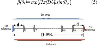
Figure (1): ULA configuration with two reference elements
according to the second reference and the array output can be expressed as
x
fst(t)=∑
Kk=1α
fst(θ) s
k(t)+
n
fst(t)
(1)
And
x
scd(t)=
∑
Kk=1α
scd(θ)β(θ
k)s
k(t)+
n
scd(t)
(2)
Respectively, where the signal steering vector with respect to first reference element is
αfst(θ)=exp{j2π(dfst/ )[0,sin(θ),…,(M-1)sin(θ)]T} (3)
Where, dfst is represents the distance between elements in the first array (with respect to first reference). The signal steering vector according to the second reference element expressed as
αscd(θ)=
exp{j2π(dscd/ )[0, -sin(θ),…,-(M-1)sin(θ)]T } (4)
Where, boldface letter represents the vector form, ‘T’ represents the transpose expression, dscd is represents the distance between element in the second array (with respect to second reference). In contrast, dfst = dscd = d, where this distance is actually in the same array but they expressed in deferent form to explain the effect of the first and second reference elements on the baseband signal. The expression β(θk) in (2) represents the phase of signal which impinges second reference element in the array with respects to the distance D = M-1 from the first reference element and it is a constant value, as
β(θk)=exp[j2π(D/ )sin(θk)] (5)
Then, nfst(t) and nscd(t) and are represent the
Gaussian noises on the receiving antennas, with unknown covariance and zero mean, they can be
expressed as σfst2IM and σscd2IM respectively, where
IM is represents the identity matrix with dimension
M.
2.2 Receiving Space Classification
Mismatch between the presumed and actual angle according to the steering vector errors leads to major error in the behavior of MVDR [8]. This problem is appeared when MVDR beamformer depends on a single covariance matrix which contains all impinging signals information. Due to the single covariance matrix the separation of the interferences and noise information becomes difficult. This problem has been solved with MUSIC beamforming algorithm, where the receiving space is divided into two sub-spaces according to the signals information [16], [17].
Inspired by the subspaces property and under assumption that the number of array’s element greater than number of incident signals M >K, the proposed beamformer collects the impinging signals’ information into two matrices according to the two references in the array. These matrices are constructed by using the auto-correlation and cross-auto-correlation of the received signals’ information. Then, actual covariance matrix (Rc) is constructed according to the actual
impinging signals. Due to the eigenvalue de-compensating property the Rc contains K non-zero
Eigen-values and M-K zero Eigen-values, where the non-zero Eigen-values represent the number of actual impinging signals and the zero Eigen-values represented the noises signals. Then, the mathematical model can be derived as
Rfstc= E[xfst(t)xfstH(t)]= ∑Nt=1 xfst(t) xfstH(t)/N (6)
= Rc+ σ2IM
Rc=Rfstc - σ2IM (7)
Rsc=E[xscd(t)xscdH(t)]= ∑Nt=1 xscd(t) xscdH(t)/N (8)
The expectation mathematical operation is represented by E [.], and ‘H’ represents the transpose conjugate (Hermitian) expression. Rfstc and Rsc are
the auto-covariance matrix and cross-covariance matrix respectively. RC matrix is comprises of K
[image:3.595.89.279.609.700.2]Rpv = ∑Ki=1 (1/μi)viviH (9)
Then, all actual data of the impinging signals on the array’s elements are collected in Rpv matrix
directly. Construction of the actual DOA in actual mode becomes easy to calculate from the combination of Rsc matrix and Rpv matrix, as in
eqn.(10)
RD=RscRpv (10)
DOA matrix contains all the actual information of the incident signals K, then Eigen-decompensating processes is done to extract the largest K Eigen-values (ei) in Rd matrix and its corresponding
eigenvectors (ui).
In this context, the estimation process is done under actual signal mode by using the K largest eigenvectors of the actual DOA matrix. The estimating angle is represents the angle which maximized the search result as
Ei(θ)= │uiHα(θ)│ (11)
i=1, 2, …, M; θ=1, 2, …,360
DOA estimation problem is represented by the number of elements in the array that must be greater than number of incident signals. The proposed beamformer overcomes this problem by using the actual information of the incident signals and using the first column in RD matrix as actual
steering vector. DOA estimation results in (11) are compared with the spectrum estimation results and corrected according it as in the next section.
2.3 Adaptive Beamforming and Interference Cancellation
Output beam radiation of each element in the array is moved toward a specific direction according to the beamformer complex weight, while array output beam pattern is produced by the intersection of these elements’ beams. Therefore, the beamformer weight must be able to ensure that the intersections points are constructs the main lobe with distortionless power in the desired signal direction and deconstructed the radiation with minimum power (null) in the direction of interference and noise. Thus, the optimization problem in MVDR beamformer expressed under minimizing the radiation power as
wopt = min wH R w s.t wHα(θd)=1 (12)
According to this equation the MVDR beamformer gives more attention to SOI direction than the direction of interferences. Conversely, another beamforming algorithm called Null Steering algorithm which gives more attention to block the direction of interferences as in[18],[19]. The optimization problem in this algorithm solved by
minw=││wHAd││ s.t wHα(θi)=0 (13) Where
wnullopt =[Ii –Ai(AiHAi)-1AiH]Ad (14)
To satisfy the proposed method’s goal and to increase the attention to the interferences direction, the proposed beamforming model constructed according to the combination between two constraints.
wopt =min wHRw
s.t wHα(θ
d)=1 and wHα(θi)=0 (15)
Where, α(θd) and α(θi) are represent the
desired signal (SOI) steering vector and interference signal steering vector respectively. Inspired by NS beamforming algorithm and according to its weight vector in eqn. (14), the actual steering vector which contains the actual information of the SOI and interferences can be constructed as
αc (θ) = [Ii - Ai(AiHAi)-1AiH] αd (θ) (16)
Where, the αd(θ) is represents the first column in
actual DOA matrix. Actual steering vector in (16) is able to satisfy the optimization problem of MVDR to minimize the power of radiation. Then, the expression in (12) can be modified as
wopt = min wH R w s.t wH αc (θ)=1 (17)
Thus, the proposed complex weight is produced according to the actual data collection as
p(θ)= [αcH(θ)RD αc (θ)]-1 (19)
Therefore, spatial direction of the inter-ference is appeared with very high sharp peak and the SOI direction is appeared with minimum power. Therefore, spatial direction of the interference is appeared with very high sharp peak and the SOI direction is appeared with minimum power
.
3. RESULTS AND DISCUSION
Simulation results are verified by using MATLAB software, a uniform linear array is used in simulations. SOI is impinging on the array’s elements from 00. The distance between elements of the array is selects to be half wavelength. The interference to noise ratio is INR= 15 dB. The number of snapshots is 1000.
3.1 DOA Estimation
First evaluation scenario verifies DOA estimation, where the proposed MVDR is firstly estimated according to the search process in (11). Constantly, if any mismatch is occurred in DOA estimation, especially when number of array’s elements and number of incident signals are equal, the proposed MVDR corrects this mismatch according to (15).
According to (11), Figure (2) shows DOA estimation results of the proposed MVDR beamforming algorithm with respects to changing the array’s elements number. Three signal sources presumed at -600, 00 and 450. It can be seen that the proposed beamformer has the exact estimation to all signal sources when the number of ULA elements M equal to K+1. A small mismatch for estimating two signal sources (at -600 and 450) occurs when the number of antenna equal to the number of signal sources (M=K=3).
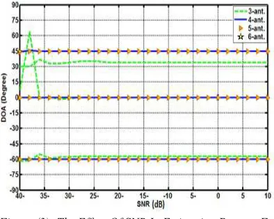
Figure (3) demonstrates the effect of varying the value of Signal to Noise Ratio (SNR) and changing the array’s elements number on the ability of the proposed MVDR beamformer to estimates the signal sources. This figure exposed that the signal estimation of the proposed MVDR has exactly DOA estimation even the SNR =-40 dB, when the number of elements in the ULA equal to M+1. The mismatch in two DOAs only occurs when the number of elements in the array is equal to the number of signal sources. The mismatch in DOA estimation occurs when the number of ULA element equal to 3 and SNR equal to (-40dB to -38 dB) at signal sources (00 and 450) and when the
SNR becomes more than -35 dB then, the mismatch occurs at the signal sources (-600 and 450).
Figure (2):Proposed MVDR Estimation Performance For Three Signals With Different Number Of Elements In
ULA
Figure (2) and figure (3) show that DOA mismatch which occurs in MVDR with respect to signal SNR metric has less effect on the proposed MVDR estimation, but the elements number in the array still effects in DOA estimation process. Thus, the proposed MVDR adds the sub-space method to overcome the estimation error and classify the impinging signal accurately.
Figure (3): The Effect Of SNR In Estimation Process For Three Signals
[image:5.595.304.508.106.291.2] [image:5.595.307.504.423.581.2]Figure (4): The Power Spectral Classification For Three Impinging Signals According To Equation (19)
3.2 Output Beamforming Pattern
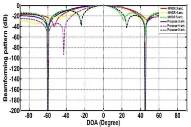
Beamforming pattern shown in Figure (5), illustrates a comparison between traditional and the proposed MVDR output performance with SNR=10. This figure shows the ability of proposed beamformer for tracking SOI and null the interferences is very clear even the ULA elements’ number equals the incident signals. According to the addition constraint in the proposed method the interference is blocked with very sharp -200 dB. Conversely, MVDR shows lower response in canceling the interferences even when number of elements in ULA increased to 6.
Figure (5): Comparison Between The Output Beamforming Pattern Of MVDR And The Proposed With
Changing The Number Of Elements To Be 3, 4 And 5
Figure (6) is presents the performance of MVDR and the proposed beamformer, where SOI is located at 0o and the interference sources are increased to be four at -30o, -50o, 30o and 60o. ULA elements is selected to be 8, INR=10 dB and SNR=10 dB. This figure shows that the proposed beamformer has the accurate performance even the number of interferences is increased. In contrast, MVDR beamformer produces a weak performance when three interferences (at -50o, 30o and 600) not
canceled exactly even the ULA elements more than the incident signals.
Figure (6): The Output Performance Of MVDR And The
Proposed Beamformer According To Increase The Impinging Signals
To explain the effects of the distance between the signal sources on the behavior of MVDR and the proposed method,consequently, the location of the interference at 30o in previous scenario has been changed to be at 50o which is close to the interference at 60o. Figure (7) shows that MVDR still has a weakness performance in cancellation of the interferences, but the case become worse in the direction of the closer sources (at 50o and 60o).
Figure (7): The Comparison Between The MVDR And The Proposed Beamformer Output Performance, When
The Signals Become Close Together With 100 Figure (8) shows the effect of increasing the SNR to be 20 dB, where the signal strength is enhanced trying to increase the sensitivity of MVDR beamformer. Unfortunately, Figure (8) result demonstrates that the MVDR still has weak performance in interferences cancelation when these interferences become close together even with 10o.
[image:6.595.89.293.105.268.2] [image:6.595.306.497.159.301.2] [image:6.595.308.503.442.568.2] [image:6.595.92.287.462.592.2]that the proposed beamformer exactly blocked the
all interferences with -200 dB.
Figure (8): The Effect Of Changing SNR To Be 20 Db On The Performance Of MVDR And The Proposed
Beamformer Output
4. CONCULOSION
This paper presents a new beam forming model that is improving the performance of MVDR in two branches; overcome the DOA estimation mismatch and cancellation the interference effect. Based on two reference elements in a single ULA and due to dividing the receiving space into two orthogonal sub-spaces the proposed beamformer extracts DOA matrix directly. Thus, the beamformer estimates the direction of radiation sources accurately, with very sharp peak; even the number of elements on the array is equal to the number of radiation sources. Two constraints are applied to optimize the output radiation pattern, where the main lobe orients to SOI direction with distortionless power and the interference direction is blocked with very deep negative power. The evaluation results demonstrate that the proposed beamformer capable to classify the impinging signals accurately with wide range of SNR even the number of interference sources are increased and close each other. The proposed model has a perfect output radiation performance since the unity gain is directed to the SOI and the interference directions are blocked with -200 dB.
REFERENCES:
[1] A. Hassanien and S. A. Vorobyov, "Phased-MIMO radar: A tradeoff between phased-array and MIMO radars," Signal Processing, IEEE Transactions on, vol. 58, 2010, pp. 3137-3151. [2] S. W. Varade and K. Kulat, "Robust algorithms
for DOA estimation and adaptive beamforming for smart antenna application," in Emerging Trends in Engineering and Technology
(ICETET), 2009 2nd International Conference on, 2009, pp. 1195-1200.
[3] H. Cox, R. M. Zeskind, and M. M. Owen, "Robust adaptive beamforming," Acoustics, Speech and Signal Processing, IEEE Transactions on, vol. 35, 1987, pp. 1365-1376. [4] D. Li, Q. Yin, P. Mu, and W. Guo, "Robust
MVDR beamforming using the DOA matrix decomposition," in Access Spaces (ISAS), 2011 1st International Symposium on, 2011, pp. 105-110.
[5] A. Khabbazibasmenj, S. A. Vorobyov, and A. Hassanien, "Robust adaptive beamforming based on steering vector estimation with as little as possible prior information," Signal Processing, IEEE Transactions on, vol. 60, 2012, pp. 2974-2987.
[6] W. Wang, R. Wu, and J. Liang, "A novel diagonal loading method for robust adaptive beamforming," Progress In Electromagnetics Research C, vol. 18, 2011, pp. 245-255. [7] F. Vincent and O. Besson, "Steering vector
errors and diagonal loading," in Radar, Sonar and Navigation, IEE Proceedings, 2004, pp. 337-343.
[8] C.-Y. Chen and P. P. Vaidyanathan, "Quadratically constrained beamforming robust against direction-of-arrival mismatch," Signal Processing, IEEE Transactions on, vol. 55, 2007, pp. 4139-4150.
[9] J. Li and P. Stoica, Robust adaptive beamforming: Wiley Online Library, 2006. [10] A. B. Gershman, Z.-Q. Luo, S. Shahbazpanahi,
and S. A. Vorobyov, "Robust adaptive beamforming using worst-case performance optimization," in Signals, Systems and Computers, 2004. Conference Record of the Thirty-Seventh Asilomar Conference on, 2003, pp. 1353-1357.
[11] A. Hassanien, S. A. Vorobyov, and K. M. Wong, "Robust adaptive beamforming using sequential quadratic programming: An iterative solution to the mismatch problem," Signal Processing Letters, IEEE, vol. 15, 2008, pp. 733-736.
[12] Y. Gu and A. Leshem, "Robust adaptive beamforming based on interference covariance matrix reconstruction and steering vector estimation," Signal Processing, IEEE Transactions on, vol. 60, 2012, pp. 3881-3885. [13] Z. Lu, Y. Li, M. Gao, and Y. Zhang,
[14] T. Xia, Y. Zheng, Q. Wan, X. Wang, and W.
Yang, "2-D Angle-of-Arrival Estimation with Two Parallel Uniform Linear Arrays," in Radar, 2006. CIE'06. International Conference on, 2006, pp. 1-4.
[15] Q.-Y. Yin, R. Newcomb, and L.-H. Zou, "Estimating 2-D angles of arrival via two parallel linear arrays," in Acoustics, Speech, and Signal Processing, 1989. ICASSP-89., 1989 International Conference on, 1989, pp. 2803-2806.
[16] W. Tao, Y. Li-sheng, L. Jian-mei, and Y. Shi-zhong, "A modified MUSIC to estimate DOA of the coherent narrowband sources based on UCA," in Communication Technology, 2006. ICCT'06. International Conference on, 2006, pp. 1-4.
[17] X. Li, G. Yang, and Y. Gu, "Simulation analysis of MUSIC algorithm of array signal proccessing DOA," in Automatic Control and Artificial Intelligence (ACAI 2012), International Conference on, 2012, pp. 1838-1841.
[18] B. Friedlander and B. Porat, "Performance analysis of a null-steering algorithm based on direction-of-arrival estimation," Acoustics, Speech and Signal Processing, IEEE Transactions on, vol. 37, 1989, pp. 461-466. [19] R. A. Qamar and N. M. Khan, "Null steering, a