PLASMA THRUSTERS
Thesis by Robert Kolasinski
In Partial Fulfillment of the Requirements for the Degree of
Doctor of Philosophy
California Institute of Technology Pasadena, California
2007
Acknowledgements
During the past five years I have been at Caltech, I have always considered myself very fortunate in two respects. First, I have been able to work on projects that I found interesting and challenging. More importantly, however, I have also had the opportunity to work with and learn from many talented and creative people on a daily basis, and these interactions have made my graduate school career a rewarding experience.
First, I am grateful to Jay Polk, my research advisor in the Advanced Propulsion Group at JPL for all of his advice and mentorship. Jay’s creativity and insight was of great benefit to my own work. I can only hope that I will be able to serve my future colleagues this well. Both Dan Goebel and Lee Johnson gave a great deal of their own time to me in helping me formulate many of the core ideas in my thesis. Their vast expertise and experience in electric propulsion was a tremendously valuable resource for me (and the rest of our group as well.) I am also thankful for Prof. Fred Culick for serving as my academic advisor at Caltech, and giving me the opportunity to pursue research projects with JPL. I would also like to acknowledge all of the assistance of my thesis committee members, David Goodwin, Paul Bellan, and Erik Antonssen.
Science Foundation (NSF) fellowship. My later work was sponsored through the Nuclear Electric Xenon Ion System (NEXIS) and NASA Evolutionary Xenon Thruster (NEXT) programs. I am very appreciative to Dan Goebel, Ira Katz, and David Vaughan (all at JPL) for their help in securing funding during the completion of my degree.
I have been very fortunate to have made great friends since I have been at Caltech. For simplicity, I’ll acknowledge those who contributed directly to the work in this report, in chronological order. Richie Wirz, a talented musician and fellow Caltech student, initially encouraged me to pursue research in advanced propulsion. Needless to say, my graduate career would have been much different and not nearly as rewarding without his advice and friendship. Dan Thunnissen, my roommate at Caltech for four years, was also my study partner for the qualifying exams. He was also a great friend, and shared with me a great deal of advice on paper writing and thesis preparation. John Ziemer (JPL), also one of my best friends, advised me on the use of UHV equipment throughout the design of the sputtering experiments. He, along with David Conroy and Lee Johnson (both from JPL) were invaluable in helping me get acquainted with the electric propulsion laboratory. In addition, my friendships with Matt Bradford and Adrian Downs (both JPL) were an integral part of my life outside of work.
I am grateful to my family in my hometown of Phillipsburg, NJ for all of their support throughout my life. This includes my brother, Michael, my grandmother, Dora, and especially my mother, Barbara, who initially fostered my interest in spaceflight and encouraged me to pursue a career in science from an early age.
Abstract
Ion thrusters offer the potential to enable many future interplanetary robotic missions presently under consideration by NASA. To realize the benefits offered by these low thrust devices, the sputtering mechanisms that are responsible for the degradation of thruster components over time must be well understood. Predictions of thruster life depend directly on the material removal rates from thruster electrodes such as the ion optics and hollow cathodes. To better understand the conditions encountered at these surfaces, this study includes an investigation of low energy sputtering at glancing incidence. Relevant ion–target combinations that were considered included Xe+ incident on Mo, C, and Cu, as well as Ar+ incident on W, C, and Cu.
To characterize the sputtering yield angular dependence experimentally, an ion beam was used to etch a coated quartz crystal microbalance. This required the development of techniques to accurately measure the incident low energy ion flux to the target and the use of surface diagnostics to investigate the properties of target materials. Measurements of C and Mo sputtering yields were obtained for Xe+ incidence angles up to 80º from the surface normal and for energies ranging from 80 eV–1 keV. In addition, existing transport theory models were used to examine projectile scattering within the different target media. The models also indicate that the sputtering behavior as a function of angle of incidence is not a strong function of energy, a conclusion that is supported by the experimental results. The surface roughness of the targets was investigated using atomic force microscopy to obtain local incidence angle distributions.
Table of Contents
Abstract………v
Table of Contents……… vii
List of Figures………. xii
List of Tables………... xv
Nomenclature……….. xvii
1 Introduction and Motivation……… 1
1.1 Ion Propulsion Overview……… 2
1.2 Principles of Operation………... 7
1.3 Damage Accumulation Caused by Sputtering……… 10
1.4 Thesis Objective……….. 12
1.5 Research Approach and Thesis Overview……….. 13
2 Relevant Experimental Data and Models for Ion Thruster Sputtering………... 15
2.1 Overview of Sputtering Physics……….. 15
2.2 Ion Thruster Endurance Test Overview……….. 17
2.3 Sputtering of the Ion Extraction Grids by Charge Exchange Ions……….. 19
2.3.1 Observations from Life Tests……….. 22
2.3.2 Modeling Approaches………..24
2.3.3 Other Grid Failure Mechanisms……….. 27
2.3.4 Summary……….. 28
2.4 Hollow Cathode Sputtering Mechanisms………28
2.4.1 Sputtering Mechanisms………... 29
2.4.2 Observations from Long Duration Tests………. 32
2.3 Concluding Remarks………... 36
3 Sputtering Models and Experimental Results for Glancing Incidence……… 39
3.1 The Binary Collision Approximation………..40
3.2 Collisions and Cross Sections………. 42
3.3 Transport Theory Models……… 45
3.3.1 Underlying Assumptions………. 46
3.3.2 General Formulation……… 47
3.3.3 Solution Method……….. 48
3.3.4 Major Results……….. 49
3.4 Monte Carlo Methods………. 50
3.4.1 General Approach……… 50
3.4.2 Implementation for Sputtering Calculations……… 51
3.5 Experimental Measurements………... 52
3.6 Empirical Models……… 57
3.7 Comparison of Experimental Data with Existing Models……….. 58
3.8 Concluding Remarks………... 59
4 Sputtering Yield Measurements at Glancing Incidence……… 61
4.1 Experimental Hardware……….. 62
4.1.1 Vacuum Facility……….. 62
4.1.2 Quartz Crystal Microbalance………... 64
4.1.3 Ion Source……… 65
4.2 Target Characterization………... 71
4.2.1 Scanning Electron Microscopy……… 72
4.3 Experimental Procedure……….. 75
4.4 Data Analysis……….. 77
4.5 Error Analysis………. 80
4.6 Results………. 82
4.7 Concluding Remarks………... 86
5 Carbon Sputtering Yield Measurements……… 89
5.1 Carbon Grid Technology Development……….. 90
5.1.1 Benefits and Development History……….. 92
5.1.2 Grid Manufacturing Processes……….93
5.1.3 Other Applications in Electric Propulsion……….. 94
5.2 Special Considerations for Carbon Sputtering……… 95
5.2.1 Crystal Structure……….. 95
5.2.2 Chemical Etching……… 96
5.2.3 Trapping of Ions within the Surface……… 99
5.3 Target Preparation and Analysis………. 100
5.3.1 SEM Images……….102
5.3.2 Raman Spectroscopy Results……….. 103
5.3.3 Summary……….. 105
5.4 Experimental Results……….. 106
5.5 Discussion………109
5.6 Concluding Remarks………... 111
6 Surface Characterization and Modeling………. 113
6.1 Analysis of Experimental Results……….. 114
6.1.3 2-D Range and Damage Distributions………. 118
6.2 Surface Height Characterization………..123
6.2.1 Atomic Force Microscope Measurements………... 125
6.2.2 Analysis of Local Angle of Incidence………..128
6.3 Concluding Remarks………... 130
7 Cathode Sputtering Measurements Using Surface Layer Activation……….. 133
7.1 Summary of Experimental Technique……… 134
7.1.1 Activation Parameters………..135
7.1.2 Calculation of Depth Calibration Curve……….. 137
7.1.3 Experimental Procedure………...138
7.1.4 Data Analysis……….. 141
7.1.5 Error Analysis……….. 142
7.2 Erosion Experiments………... 145
7.2.1 Thruster Hardware……….. 145
7.2.2 Experimental Conditions and Results………..148
7.3 Discussion………150
7.3.1 Replication of LDT Wear Rates……….. 150
7.3.2 Repeatability……… 152
7.3.3 Sensitivity of Erosion Rate to Keeper Potential……….. 152
7.3.4 Variation of Erosion Rate with Throttle Level……… 153
7.4 Conclusions……… 155
8 Concluding Remarks………. 157
8.1 Additional Contributions………. 159
A Transformation to Beam-Centered Coordinates………165
B Cathode Keeper Orifice Wear………..166
List of Figures
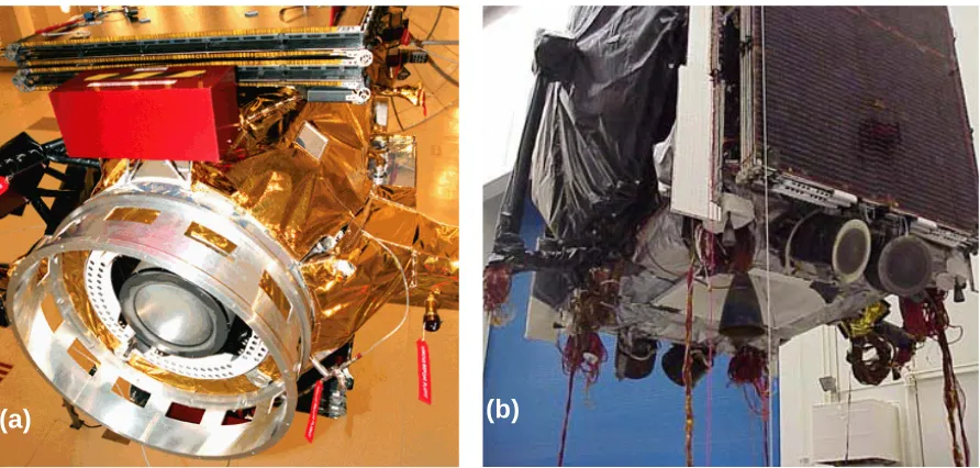
1.1 The NSTAR thruster mounted on the Deep Space 1 spacecraft and the Boeing XIPS-25
thrusters mounted on a 702 communications satellite………3
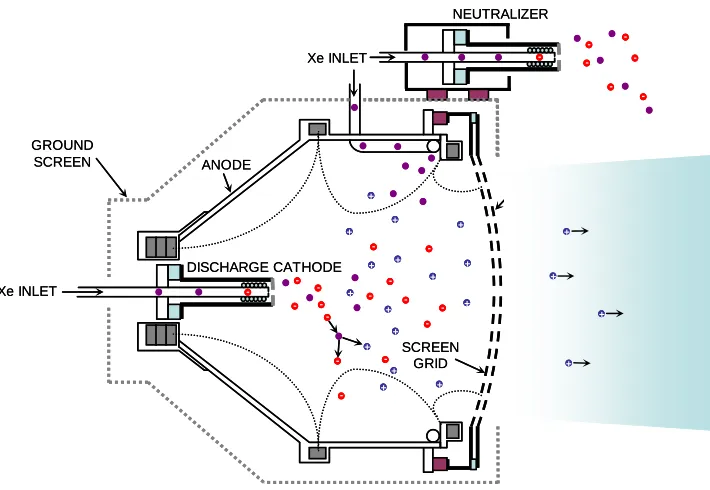
1.2 Schematic of a typical ion thruster configuration……….. 9
1.3 Ion thruster electrical diagram……… 11
2.1 Cross section of a single ion thruster beamlet……… 20
2.2 Charge exchange collision schematic……… 22
2.3 Downstream surface of an accelerator grid after 8200 hours of operation and cross-section showing pits and grooves erosion profile………...23
2.4 Accelerator grid downstream surface showing severe sputter damage, with wear-through pits between the holes………... 24
2.5 CEX ion energy distributions for ions striking accelerator grid hole walls in NSTAR and NEXIS configuration thrusters………25
2.6 CEX ion impact angle distribution for the NSTAR and NEXIS configuration ion thrusters…. 26 2.7 Cut-away view of a typical hollow cathode……… 29
2.8 Photographs of the EMT2 keeper at the conclusion of the 8200 hr LDT………... 31
2.9 Evolution of the cathode keeper surface during the ELT………... 34
2.10 ELT cathode keeper orifice area as a function of time………... 34
2.11 Photographs indicating cathode spot position for ¼ in. cathode operating at TH 15, TH 12, TH 8, and TH 4………...37
3.1 Binary collision geometry………...40
3.2 Comparison of Thomas-Fermi and Hartree-Fock-Slater charge distributions for Mo…………46
3.3 Typical experimental setup for sputtering measurements………...54
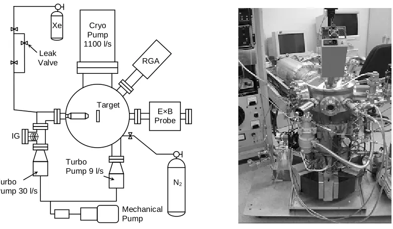
4.1 Sputtering facility schematic and photograph……… 63
4.2 QCM holders used for normal incidence and glancing incidence……….. 64
4.3 Ion beam diagnostics……….. 66
4.4 Cross sections for Xe+ - Xe collisions measured by Pullins………... 66
4.5 Pretest and posttest beam current density profiles for 300 eV Xe+ ions……… 67
4.6 Constant current lines for a 300 eV Xe+ ion beam mapped as a function of deflection voltage……… 69
4.7 E×B probe traces for varying discharge voltages………... 70
4.8 SEM image revealing the surface topography of a Mo film………... 72
4.9 SEM image of a cross section of a crystal fractured in liquid nitrogen……….. 73
4.10 X-ray diffraction scans of Mo-coated and blank QCMs………. 74
4.11 Measured Mo film thickness change during bombardment by 1 keV Xe+ ions………. 76
4.12 Beam current density profile showing errors caused by probe averaging……….. 80
4.13 Xe+→Mo normal incidence sputtering yield measurements for 80 eV to 1000 eV…………... 84
4.14 Cu and W sputtering yield measurements for Ar+ bombardment at normal incidence……….. 85
4.15 Sputtering yield variation for Xe+→Mo as a function of angle of incidence………. 85
5.1 Structure of a graphite crystal………. 87
5.2 Sputtering yields of pyrolytic graphite measured by Hechtl for O+, Ne+, and C+ beams at normal incidence……… 93
5.3 RGA spectrum showing the working gas composition………...94
5.4 Etch profile for 300 eV Xe+ incident on a C target……… 96
5.5 SEM image showing the carbon film cross-section……… 99
5.6 SEM image of the carbon film topography……… 99
5.9 Xe+→C sputtering yields at normal incidence……… 103
5.10 Carbon sputtering yields at varying incidence under Xe+ bombardment………104
6.1 Normalized sputtering yield plots for the experimental data collected in the present study….. 115
6.2 Coordinate system for range and damage distribution calculations………116
6.3 Damage distribution for C and Mo collision cascades………... 121
6.4 Range distribution for C and Mo collision cascades……….. 122
6.5 Longitudinal and transverse straggling as a function of mass fraction………... 122
6.6 Ratio of transverse to longitudinal straggling as a function of mass fraction……… 123
6.7 Local angle of incidence for a rough surface……….. 124
6.8 AFM schematic and SEM image of Veeco TESP-HAR tip………... 126
6.9 Carbon sample AFM scan, 5μm × 5 μm area………..127
6.10 3-D carbon sample surface height map of a 5 μm square region; surface height distribution function………127
6.11 Local angle of incidence distribution………..129
7.1 Image showing cathode keeper placement in 30 cm laboratory model thruster………. 134
7.2 Radiograph of activated cathode keepers with gamma-sensitive photographic paper…………137
7.3 Activity vs. depth profile for 11 MeV proton beam activation of Mo95……… 138
7.4 Schematic of NaI(Tl) detector setup………... 140
7.5 Tc95m spectra scans from Ge(Li) and NaI(Tl) detectors………. 140
7.6 Range of discharge parameters for NSTAR configuration thrusters……….. 148
7.7 Extrapolated erosion profile after 8200 hours of operation at TH 15……… 150
7.8 Downstream keeper surface before and after 70 hours of operation at TH 15………... 151
B.1 Cathode keeper with polished orifice wall………..167
List of Tables
1.1 Electron bombardment ion thruster development history………... 61.2 Ion thruster operating parameters………10
2.1 NSTAR life test history……….. 18
2.2 Throttle level set points for the Extended Life Test………34
3.1 Heavy ion sputtering experimental results……….. 56
4.1 Ion beam current density and FWHM for the operating conditions of this study………...68
4.2 Double ion content as a function of discharge voltage………... 71
4.3 Cu and W film deposition parameters……… 71
4.4 Normal incidence yield measurements………... 84
4.5 Angular dependence of Xe+→Mo sputtering yields………... 86
5.1 Normal incidence carbon yield measurements………103
5.2 Xe+→C sputtering yields at varying angles of incidence………104
5.3 Carbon sputtering yield fit parameters……… 106
6.1 Spatial moments for a planar source coordinate system………. 117
6.2 Spatial moments for a 3-D beam-centered coordinate system………117
6.3 Projectile ranges for Xe+ incident on C and Mo………. 124
7.1 Properties of activated products over the range of interest in this experiment………... 141
7.2 NKO vs. FT2 performance over the entire NSTAR throttle range………. 147
7.3 NKO vs. EMT4 keeper ion current and double ion current along the thruster centerline…….. 147
7.4 TH 15 erosion rate test results……… 147
Nomenclature
a = reference count rate
aI = interatomic screening length ao = Bohr radius (0.0529 nm) aTF = Thomas-Fermi screening length cf = QCM sensitivity function E = incident particle energy
h = number of isotopes present in sample spectrum
hE = QCM electrode thickness ho = QCM half-thickness
Hl = Hermite polynomial of order l Isp = specific impulse
J = current
j = current density
k = Boltzmann’s constant (8.6171×10⁻⁵ eV/K)
l = grid separation gap
m = spectrum scaling parameter
cath
m& = cathode flow rate
main
m& = main flow rate
neut
m& = neutralizer flow rate
mi = ion mass
M1 = atomic mass, incident particle
b
nv = vector aligned along direction of incident ion beam
N = target number density
Pl = Legendre polynomial of order l q = elementary charge (1.6022×10⁻¹⁹ C)
R = QCM radius of curvature
Rp = projected range
Sn = nuclear stopping power
t = time
T = energy transferred to recoiling particle
Te = electron temperature
Tw = cathode insert wall temperature
u = velocity
Us = surface binding energy
V = voltage
W = weight factor array
Y = sputtering yield
y = sample count rate
z = total counts
Z1 = atomic number, incident particle
Z2 = atomic number, recoil
α = local angle of incidence
γ = reduced mass
εo = permittivity of free space (8.8542×10⁻¹² C2/N·m2)
λ = wavelength
ν = frequency
νn = normalized spatial moment of order n
ρ = density
σ = cross section
τ = spectrum live time
τmeas = measured thickness change
φ = potential
φe = effective work function
Φ = interatomic screening function
Acronyms
AES Auger emission spectroscopy AFM atomic force microscope BCA binary collision approximation
C-C carbon-carbon composite
CEX charge exchange
CVD chemical vapor deposition DS1 Deep Space 1
ELT Extended Life Test
EMT engineering model thruster
FT flight thruster
JPL Jet Propulsion Laboratory LDT Life Demonstration Test LEED low energy electron diffraction MiXI Miniature Xenon Ion Thruster
NASA National Aeronautics and Space Administration NEXIS Nuclear Electric Xenon Ion System
NEXT NASA Evolutionary Xenon Thruster
NSTAR NASA Solar Electric Propulsion Technology Applications Readiness QCM quartz crystal microbalance
RGA residual gas analyzer
SEM scanning electron microscope SEP solar electric propulsion SLA surface layer activation TRIM Transport of Ions in Matter
UCSD University of California, San Diego
UHV ultra-high vacuum
Chapter 1:
Introduction and Motivation
Ion engines are characterized by their high specific impulse capability and superior overall efficiency when compared to their chemical thruster counterparts. This makes them uniquely suited for many specialized propulsion applications and an enabling technology for missions where high precision or large velocity change (ΔV) requirements preclude the use of more conventional propulsion devices. Because of their low thrust, long periods of operation (on the order of 2 to 10 years) are required to realize these benefits.
To generate thrust, most contemporary ion engine designs create a xenon plasma using a hollow cathode and a discharge chamber with a ring-cusp magnetic field. Xenon ions from the plasma are accelerated electrostatically through a set of grids. Both the cathode and grids are constantly exposed to energetic ions and are susceptible to sputtering, a process defined as the “removal of surface atoms due to energetic particle bombardment.” [Berhisch, 1981] Over time, the material removed through sputtering causes significant modifications to the geometry of these components, resulting in changes that adversely affect performance and lead to thruster failure. Predicting the rate at which these changes occur is a key component of assuring adequate propellant throughput and service life capability.
bombardment conditions that are relevant to ion thrusters has inhibited the development and implementation of such models.
In this thesis, the issues associated with these complex material removal processes are addressed through a combination of experiments and modeling. This chapter outlines the benefits of ion propulsion, which motivate this study, along with the basic principles of operation. A more detailed discussion of the role of sputtering in ion thrusters is also provided. A summary of objectives follows, and the chapter concludes with an overview of this thesis.
1.1
Ion Propulsion Overview
For many ambitious applications, the propulsion system requirements dictate the feasibility and overall difficulty of a given space mission [Frisbee, 1996]. Many low ΔV (hence, less propulsively demanding) applications such as inner planet landers and orbiters, robotic flybys of the outer planets, and low Earth orbit human missions, have already been successfully accomplished. Chemical thrusters using solid or liquid propellants were selected almost exclusively for these applications, with the reasoning that extensive development had already been devoted to their optimization. Given their heritage in flight applications, chemical rockets were generally considered “mature” technologies. These initial missions have paved the way for more ambitious applications (sample return, outer planet orbiters, multiple body rendezvous, and interstellar precursor) requiring capability for much higher ΔV [Polk, 2003]. For many of these missions, use of an electric propulsion system may have the practical benefit of significant savings in propellant mass (thereby increasing the deliverable payload) and trip time. More importantly, many new electric propulsion systems under development serve as enabling technologies, allowing for missions that would otherwise be impossible with more conventional chemical propulsion.
velocity depends on the accelerating potential through which the ions pass, allowing high specific impulses to be achieved in this manner. The beam ion energy cost εB is an important metric for evaluating thruster performance; εB is defined as the discharge power devoted to creating each extracted beam ion:
B D D B= JJV
ε 1.1
Note JD and VD are the discharge current and voltage, respectively, and JB is the total beam current. Another important metric is the propellant utilization efficiency ηu, which is defined as the fraction of the propellant that is eventually accelerated to form the beam:
q m m
J i
T B u
&
=
η 1.2
In the above expression, mi refers to ion mass, q is the electronic charge, and m&T is the total
propellant mass flow rate. For modern thruster designs, εB = 180 eV/ion and ηu = 90%. The efficient use of propellant and power is an important aspect of realizing the advantages of operating at high Isp. However, the need for an external power system represents a limitation on the thrust capability of these devices. With the power density of state of the art solar arrays at approximately 30 kg per 1
[image:23.612.94.540.79.292.2](a) (b)
energy liberated through the combustion of propellants in large chemical rockets. Despite thrust limitations, better overall efficiency and higher specific impulse compared to chemical thrusters has allowed ion thrusters to be advantageous for missions where increased trip time may be traded for increased payload mass or decreased spacecraft mass (so a smaller launch vehicle may be used.) In addition, the time of flight for many longer duration deep space missions may be shortened with electric propulsion.
1.1.
In parallel with these efforts in the United States, significant ion thruster development has also occurred within the international community. Research of radio-frequency (RF) ionization of gases at Germany’s University of Gieβen during the 1960’s provided the initial motivation for ion thruster development in Europe [Bassner, 1994]. With an RF design, energy for ionization is created using a high frequency generator coil positioned around a quartz discharge chamber. This is in contrast to designs used in the United States which utilize a hollow cathode-anode configuration. During the 1970’s, industrial development of 10 cm ion thrusters proceeded to bring the technological maturity of these devices to a level suitable for flight applications. The first flight test of an RF ion thruster by the European Space Agency (ESA) occurred as part of the EURECA mission, launched in 1992 aboard the space shuttle [Bassner, 1994]. The maximum thrust of the ion engines on this mission was 10 mN at an input power of 400 W, with an Isp of 4700 s. The thrusters successfully operated for a total of 240 hours, and were later retrieved with the space shuttle during STS-57 in 1993.
Recent work by the Japan Aerospace Exploration Agency (JAXA) has involved the development of 35 cm diameter ion thrusters [Hayakawa, 2002]. These thrusters generate a plasma discharge with a hollow cathode and use xenon propellant. With a maximum thrust of 150 mN at a power level of 3.4 kW, the performance of these thrusters is comparable to most state of the art designs currently in
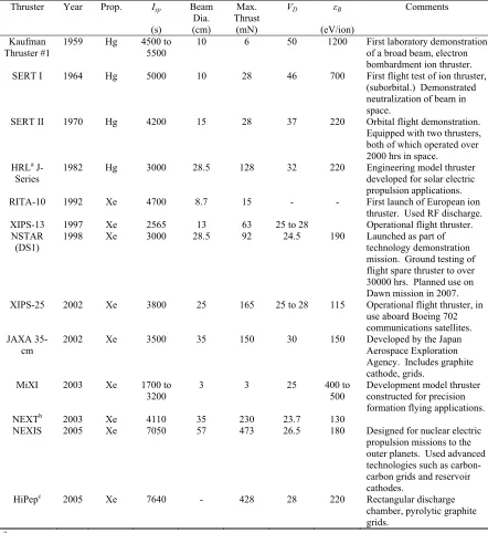
Table 1.1: Electron-bombardment ion thruster development history.
Thruster Year Prop. Isp
(s) Beam Dia. (cm) Max. Thrust (mN)
VD εB
(eV/ion)
Comments Kaufman
Thruster #1
1959 Hg 4500 to 5500
10 6 50 1200 First laboratory demonstration of a broad beam, electron
bombardment ion thruster. SERT I 1964 Hg 5000 10 28 46 700 First flight test of ion thruster,
(suborbital.) Demonstrated neutralization of beam in space.
SERT II 1970 Hg 4200 15 28 37 220 Orbital flight demonstration. Equipped with two thrusters, both of which operated over 2000 hrs in space. HRLa
J-Series 1982 Hg 3000 28.5 128 32 220 Engineering developed for solar electric model thruster propulsion applications. RITA-10 1992 Xe 4700 8.7 15 - - First launch of European ion
thruster. Used RF discharge. XIPS-13 1997 Xe 2565 13 63 25 to 28 Operational flight thruster. NSTAR
(DS1)
1998 Xe 3000 28.5 92 24.5 190 Launched as part of technology demonstration mission. Ground testing of flight spare thruster to over 30000 hrs. Planned use on Dawn mission in 2007. XIPS-25 2002 Xe 3800 25 165 25 to 28 115 Operational flight thruster, in
use aboard Boeing 702 communications satellites. JAXA
35-cm 2002 Xe 3500 35 150 30 150 Developed by the Japan Aerospace Exploration Agency. Includes graphite cathode, grids.
MiXI 2003 Xe 1700 to
3200 3 3 25 400 500 to Development model thruster constructed for precision formation flying applications. NEXTb 2003 Xe 4110 35 230 23.7 130
NEXIS 2005 Xe 7050 57 473 26.5 180 Designed for nuclear electric propulsion missions to the outer planets. Used advanced technologies such as carbon-carbon grids and reservoir cathodes.
HiPepc 2005 Xe 7640 - 428 28 220 Rectangular discharge
chamber, pyrolytic graphite grids.
aHughes Research Laboratories
program has been on understanding and enhancing thruster life. In particular, graphite hollow cathodes and grids have been incorporated into thruster designs. Laboratories in Japan have also initiated several endurance testing programs aimed at identifying new thruster failure modes [Hayakawa, 2002; 2004].
An abbreviated summary of electron bombardment ion engines is given in Table 1.1. From this information, the recent technology development trend focusing on the scaling of the thruster discharge chamber size for different applications can be clearly seen. At the extremes of these efforts are the 3 cm Minature Xenon Ion (MiXI) thruster (designed for precision formation flying missions) [Wirz, 2004] and the 65 cm Nuclear Electric Xenon Ion System (NEXIS) thruster (for high power nuclear electric propulsion.) [Polk, 2003] Efforts to improve thruster service life represent another important long term development trend. Newer thruster designs have emphasized the use of sputter resistant materials, such as carbon composites. Also visible from Table 1.1 is the long term trend of decreasing the voltages of components that are exposed to the discharge plasma, a technique that has been used to decrease wear of thruster components. Note that the data in Table 1.1 indicate typical values of each design near its maximum throttle level.
1.2
Principles of Operation
negated by the additional equipment mass needed to vaporize the propellant and the additional safety concerns associated with ground testing.
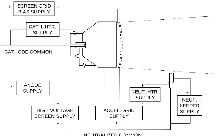
The ion thruster electrical schematic shown in Figure 1.3 displays the power supplies needed to ionize the propellant and extract a beam. The screen supply raises the thruster body along with the discharge plasma within it to a high voltage with respect to spacecraft ground (1100 V for a typical 30 cm thruster.) Ions within the discharge chamber drift toward the screen grid apertures and are accelerated out of the thruster by the force imparted by moving through this voltage difference. This is the mechanism by which thrust is generated. Because the entire thruster has been biased to a high positive voltage, a negatively biased accelerator grid is positioned just downstream of the screen grid to prevent electrons from backstreaming into the discharge chamber.
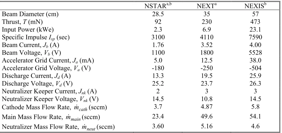
Table 1.2 is provided to give the reader a feel for the magnitudes of the controllable voltage and current parameters and the mass flow rates for the maximum throttle level of several modern ion thruster designs. It should be noted that the beam current is not directly controlled by the screen power supply, but indirectly through adjustments in the discharge current.
Xe INLET GROUND SCREEN Xe INLET ACCEL GRID SCREEN GRID ANODE DISCHARGE CATHODE -+ + + + -+ + + + -- -+ + + + + + + + + -+ + + -Xe INLET GROUND SCREEN Xe INLET ACCEL GRID SCREEN GRID ANODE DISCHARGE CATHODE --+ + + + + + + + --+ + + + + + + + ---- --+ + + + + + + + + + + + + + + + + + --+ + + + + +
[image:29.612.144.499.73.318.2]NSTARa,b NEXTa NEXISb
Beam Diameter (cm) 28.5 35 57
Thrust, T (mN) 92 230 473
Input Power (kWe) 2.3 6.9 23.1
Specific Impulse Isp(sec) 3100 4110 7590
Beam Current, Jb(A) 1.76 3.52 4.00
Beam Voltage, Vb(V) 1100 1800 5528
Accelerator Grid Current, Ja (mA) 5.0 12.5 38.0
Accelerator Grid Voltage, Va(V) -180 -250 -504
Discharge Current, Jd(A) 13.3 19.5 25.9
Discharge Voltage, Vd(V) 25.2 23.7 26.3
Neutralizer Keeper Current, Jnk(A) 2 3 3
Neutralizer Keeper Voltage, Vnk(V) 14.5 10.8 14.5
Cathode Mass Flow Rate, m&cath(sccm) 3.7 4.87 5.8
Main Mass Flow Rate, m&main(sccm) 23.4 49.6 54.1
Neutralizer Mass Flow Rate, m&neut(sccm) 3.60 5.16 4.6
aDeveloped by NASA Glenn Research Center bDeveloped by NASA Jet Propulsion Laboratory
To prevent the spacecraft from accumulating a large negative charge, an additional hollow cathode is positioned outside the thruster to emit electrons. This cathode is aptly named the
neutralizer. A keeper electrode surrounding the cathode maintains a discharge. The potential of the neutralizer cathode typically floats lower than the space plasma potential to allow electrons to be drawn into the ion beam for the purpose of neutralization.
1.3
Damage Accumulation Caused by Sputtering
Ion thrusters provide much lower thrust compared to chemical thrusters, given that the power generated by the combustion of propellants cannot be matched by any practical electrical power technology presently available. Because of this, ion thrusters must perform reliably over long periods of time. For lower ΔV solar electric propulsion (SEP) missions, the time of flight may be on the order of 3 to 5 years. For higher powered missions, over 10 years of continuous operation may be needed.
[image:30.612.69.531.89.307.2]attains an energy greater than that binding it to its nearest neighbors, it will be ejected. The accelerator grid is especially susceptible to damage in this manner from bombardment by charge exchange ions created in between the grids. In addition, the surfaces of the discharge cathode and screen grid are constantly exposed to the discharge plasma and are therefore subjected to wear processes. In each of these cases, sputtering changes the geometry of these components to the extent that they are no longer able to fulfill their intended function, resulting in thruster failure. Understanding these processes and being able to predict wear rates are necessary for assessing propellant throughput capability at different throttle levels, and is essential information to systems engineers from the earliest stages of mission design.
Assuring that sufficient ion thruster life can be achieved is a difficult process. In the past, the technique of choice for accomplishing this objective had been long duration testing. Although there are many benefits to this, it is an unrealistic method for establishing useful thruster lifetimes when the required burn times are in excess of 3 to 5 years. Reliance on life testing alone also inhibits new
SCREEN GRID BIAS SUPPLY
CATH. HTR. SUPPLY
ANODE SUPPLY
HIGH VOLTAGE SCREEN SUPPLY
ACCEL. GRID SUPPLY CATHODE COMMON
NEUTRALIZER COMMON NEUT. HTR.
SUPPLY NEUT.
KEEPER SUPPLY
-+
+
-+
-+
- +
-+
-+
[image:31.612.147.502.103.326.2]
thruster development, as it is impractical to optimize designs based on the construction and testing of prototypes. This indicates the need for sophisticated design tools and models that are capable of optimizing the ion engine for a combination of both performance and service life. This requires accurate knowledge of both the ion bombardment conditions at the different thruster surfaces as well as the sputtering yields of electrode materials under these conditions.
Despite the great deal of research that has been conducted in the field of sputtering [Smentkowski, 2000], significant gaps in experimental data exist for conditions that are of interest to ion propulsion applications. Most studies have previously focused on yield measurements at normal incidence; the dependence of yield on angle of incidence has been investigated far less extensively [Berhisch, 1981]. Most of the data from these studies have been obtained for high energy (10-100 keV) light ions. However, for the wear conditions of interest to ion propulsion, low energy (<1 keV) heavy ion bombardment at varying angles of incidence is required. Existing theoretical and computational models applied to this sputtering regime do not provide the level of accuracy required for life assessment.
1.4
Thesis Objective
expected that the results obtained in this study will have much broader applications. Ion beam etching of surfaces has become an important fabrication technique for a wide range of industrial processes, and the ability to create surface structures smaller than 1 μm in width has been applied by the electronics industry to the fabrication of integrated circuits [Lee, 1979] and hard disk drive heads [Hsiao, 1999]. Sputtering has also become ubiquitous throughout surface science, and is used for ion depth profiling and surface cleaning [Oura, 2003]. In addition, sputtering has been found to have a negative impact as a contamination mechanism in fusion plasmas [Behrisch, 1981].
1.5
Research Approach and Thesis Overview
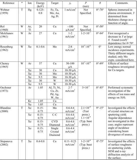
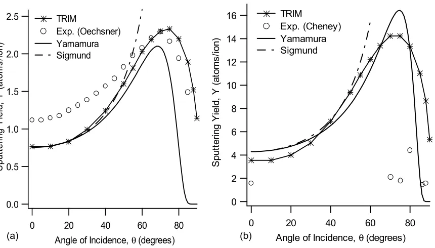
This thesis is subdivided into three parts, beginning with a review of ion thruster sputtering processes. Chapter 2 begins with a detailed discussion of the physics of sputtering. The collision processes by which energy is transferred from incident particles to a solid medium are discussed. Also, the plasma bombardment conditions that are of interest to grid and cathode sputtering are established based on a review of prior thruster experimental and modeling work, including the results of long duration wear tests. Chapter 3 provides a literature review of existing sputtering models which are relevant to ion thruster sputtering. A review of previously published sputtering yield measurements at glancing incidence is provided at the end of this chapter, along with a comparison between the predictions of the models and the prior experimental data.
normal incidence are presented as a validation of the experimental method, along with the first measurements of grazing incidence molybdenum measurements. The QCM technique was then modified to allow for carbon sputtering yield measurements, as discussed in Chapter 5. Because the change in mass of the target is measured in-situ, implantation of Xe in the C surface is observed. Experimental measurements of C sputtering yields at grazing incidence are presented, the first such results for this material under Xe bombardment. The experimental results are modeled in Chapter 6 using existing transport theory approaches. A detailed characterization of the surface topography is undertaken in this chapter as well to characterize its influence on the yield measurements.
The final part of the thesis includes an experimental examination of cathode sputtering in ion thrusters. In the cathode region of the discharge chamber, the plasma bombardment conditions are not well known, making the sputtering data obtained previously of limited use for this region. In this case, a technique known as surface layer activation (SLA) is used to measure wear rates directly by using components activated with a high energy ion beam to create a radioactive tracer in the near surface region. This technique is discussed in detail in Chapter 7. The dependence of cathode wear rate is determined as a function of throttle level. Techniques to combat erosion, such as biasing the cathode keeper electrode, are also discussed.
Chapter 2:
Relevant Experimental Data and Models for
Ion Thruster Sputtering
Sputtering processes are responsible for the accumulation of damage to the ion thruster grids and cathodes over time. Since both the cathode and grid assemblies are critical for long duration operation, thruster life is directly related to the amount of damage sustained by these components through sputtering. This chapter begins with an overview of the physics of sputtering by energetic particle bombardment to provide the framework needed to understand thruster wear processes. The mechanisms for energy transfer between incident ions and the target medium are discussed as well as the ejection process for surface atoms.
Specific wear mechanisms associated with the ion thruster grids and cathodes are addressed in the second portion of this chapter, along with an analysis of previous endurance testing. These tests establish the wear problems that will be addressed by the experimental investigation discussed in the rest of this thesis and are used to provide insight into the fundamental physics of ion thruster sputtering. An analysis of recent experimental and computation studies on the plasma conditions near the grids and discharge cathode is also provided in order to establish the bombardment conditions that are of interest. The chapter concludes with a discussion of the material properties that influence sputtering yields.
2.1
Overview of Sputtering Physics
It is useful to define a sputtering yield, which is the number of target atoms removed per incident ion. Expressed in the form of an equation, the sputtering yield is [Smentkowski, 2000]:
i t N N
Y = 2.1
Note that in the above expression, Nt is the number of target atoms removed and Ni is the number of incident ions. The earliest attempts at measuring sputtering yields were performed Kingdon and Langmuir (1923) using plasma discharges. The yield, as defined by Equation 2.1, is particularly useful for calculating the erosion rates of materials under different ion bombardment conditions because it allows the material removed by sputtering to be related directly to the incident ion flux. However, it is important to recognize that the sputtering yield, Y, summarizes a great deal of information into a single parameter. In fact, Y depends on the incident ion mass and energy, target medium atomic mass, surface roughness, angle of incidence, and numerous other parameters. Because of this, a challenge of analyzing the sputtering behavior of different materials experimentally is isolating the key processes which are of interest [Anderson and Bay, 1981].
In sputtering processes, surface atoms may be removed through a number of fundamentally different mechanisms. The first of these processes, known as physical sputtering, is the transfer of kinetic energy from the incident particle to the atoms of the target medium through collisions [Berhisch, 1981]. The atoms which receive kinetic energy from the incident particle are referred to as
recoils. In such a case, the incident particle impacts the surface and undergoes a number of collision steps, losing energy in the process. If a sufficient amount of energy is transferred to atoms near the surface, these atoms may attain enough kinetic energy to overcome the surface binding energy of the solid, Us. The surface binding energy is generally treated as the potential barrier which must be overcome for a surface atom to break its bonds with all of its nearest neighbor atoms.
electric propulsion applications, where inert gases are used in plasma discharges. However, for cases where the incident particles chemically react with the target surface, chemical sputtering may have a much more significant impact on target erosion [Berhisch, 1981]. In this instance, incident ions which become implanted within the target medium form chemical bonds with the surrounding atoms. If the concentration of imbedded ions is sufficiently large, the binding energy of the surface may be significantly altered.
2.2
Ion Thruster Endurance Test Overview
Endurance testing has played an important role in ion thruster technology development. In many cases, this was the only means of validating the propellant throughput capability of a particular engine design. For obvious reasons, such information is vital from a systems engineering standpoint at the earliest design stages for a given spacecraft. The need for adequate life and long duration testing was recognized in the earliest ion thruster work [Kaufman, 1961]. During the 1970’s, Hughes Research Laboratories devoted a great deal of effort to testing its J-series 30 cm diameter mercury thruster designs [Maloy, 1981]. A great deal of the present understanding of cathode sputtering is derived from a series of endurance tests as part of the NASA Solar Electric Propulsion Technology Applications Readiness (NSTAR) program. Spanning most of the 1990’s, this program developed the 30 cm xenon ion thruster used on the DS1 spacecraft and included four long duration tests on engineering model (EMT) and flight (FT) engines. The testing chronology is presented in Table 2.1.
flakes which became lodged in the grid apertures, resulting in aberrant erosion in these regions. Despite these difficulties however, it was estimated that all components of the thruster assembly would withstand over 4100 hours of operation [Hayakawa, 2001].
In support of the European Space Agency’s (ESA) ARTEMIS mission, a successful 15000 hour life test of a 10 cm diameter radiofrequency thruster system (RITA) was conducted under the leadership of Astrium [Killinger, 2001]. The purpose of this endurance test was to validate the ion propulsion system for north-south station keeping functions. The RF power required to maintain a constant beam current was observed to increase as a result of erosion to the grid apertures [Killinger, 2000]. During this test, a total impulse of over 700,000 N·s was attained, with a projected thruster life at its maximum throttle level well in excess of the 15000 hour test duration [Killinger, 2001].
Long duration testing is valuable from a technology development standpoint because it allows for the identification of thruster failure modes and provides guidance for future design improvements. Such was the case during the NSTAR program, when an initial 2000 hr wear test of a 30 cm
Table 2.1: NSTAR life test history.
Year Location Hours Test Article Erosion 1995
NASA Glenn Research
Center 2150 EMT 1
Test operated at maximum throttle setting. Severe cathode wear observed. Significant flakes deposited on discharge chamber interior, severe screen grid erosion [Patterson, 1995]. 1995 NASA JPL 1024 EMT 1b
Test operated at maximum throttle setting. Keeper electrode introduced, change reduced cathode wear significantly. Discharge flake retention mesh included. Minimal observed screen wear [Polk, 1996].
1996a NASA JPL 8192 EMT 2
Test operated at maximum throttle setting. Posttest analysis showed keeper orifice plate reduced in thickness by 33%. Deposits observed on upstream surface [Polk 1999].
1998 – 2003b NASA JPL 30352 FT 2
First 4937 hrs of test operated at maximum throttle setting. Higher than expected keeper wear observed after thruster throttled down to an intermediate power level. Keeper completely destroyed by end of test, significant cathode chamfering found during posttest analysis. After 30000 hrs of operation, complete wear-through between accelerator grid apertures observed [Sengupta, 2003].
engineering model thruster revealed higher than expected wear of the cathode and screen grid [Patterson, 1995]. A number of engineering solutions incorporated into the thruster design mitigated these problems, as verified in later testing [Polk, 1996].
A literature review by Brophy (1996) examined over 60 thruster wear tests conducted between 1962 and 1995, in which 18 different failure modes were identified. This review summarizes findings from tests conducted both within the United States and abroad. An important observation from Brophy’s review is that the sputtering phenomena of interest occur very slowly, and it is therefore impractical to accumulate wear data for the entire throttle range of a given thruster or to iterate over different design options efficiently. For missions requiring relatively large ΔVs, thruster operating times in excess of 80000 hours may prohibit testing to the full lifetime of the thruster prior to launch. For these purposes, being able to accurately predict material removal rates from thruster electrodes using computational modeling or shorter duration wear tests is essential.
2.3
Sputtering of the Ion Extraction Grids by CEX Ions
The process by which ions are extracted though the grids was understood well before the construction of the first ion thruster in 1959, based on prior theoretical and experimental work by Child (1911) and Langmuir (1913). In these studies, the maximum current density that can be extracted through a set of parallel planes is given by
2 2 / 3 2 / 1 2 9 4
l m
q j
i
o φ
ε ⎟⎟ ⎠ ⎞ ⎜⎜ ⎝ ⎛
= 2.2
This is the well-known Child-Langmuir law, which gives the space charge limited current density j
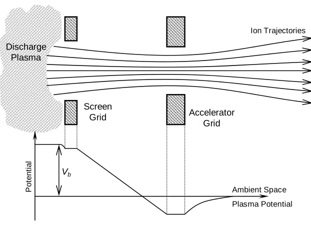
A cut-away view of a single ion thruster beamlet is shown in Figure 2.1, along with the potential along the grid aperture centerline. The ions within the discharge plasma are at a potential Vb (known as the net beam voltage) above the space plasma potential. With the screen grid tied electrically to the cathode, the potential difference between the plasma and screen is equal to the discharge voltage
Vd. The ion acceleration is not strictly a 1-D process, and the ion trajectories are influenced greatly by the shape of the plasma sheath that forms at the edges of the screen apertures. These ions enter the sheath with the Bohm velocity, which depends on electron temperature, Te [Chen, 1965]:
i e
bohm m
qT
u = 2.3
As ions move through the screen grid apertures, they experience a large potential drop through which they are accelerated to their exit velocity. Electrons are reflected away from the screen grid, and the electron density in the inter-grid region is usually negligible for most practical calculations [Anderson, 2004]. For well-designed optics operating with the intended potentials and plasma
Discharge Plasma
Screen
Grid Accelerator
Grid
P
o
tent
ia
l
Ambient Space
Plasma Potential Ion Trajectories
[image:40.612.130.441.109.335.2]Vb
densities, the sheath takes on a concave shape, focusing the ions through the apertures in a well-collimated beamlet. This configuration is depicted in Figure 2.1. Excessive plasma density for a given total accelerating voltage may cause a convex sheath, resulting in divergent beamlets and poor focusing. In particularly severe cases, direct impingement of ions on the accelerator grid and the formation of rouge holes may result.
The accelerator grid does not actually play a role in the ion acceleration process. Its primary function is to prevent electrons from backstreaming into the discharge chamber, which is biased positive with respect to the ambient space plasma potential. Downstream of the accelerator grid, the individual beamlets combine to form a single broad beam. Electrons from the neutralizer eventually enter the plume and neutralize the beam farther downstream of the thruster.
Un-ionized propellant atoms, unaffected by the potential gradients within the thruster, also drift through the ion optics apertures through the process of free molecular flow. The loss of neutrals from the discharge chamber in this manner adversely affects thruster performance, and small hole accelerator grid (SHAG) optics have been used to mitigate this effect. Such an approach is used in all modern ion thruster designs to improve propellant utilization efficiency. The presence of neutrals in the inter-grid region also introduces the possibility of collisions with high energy ions. Such collisions involve strong interactions between the electron shells of the two particles and commonly result in the transfer of an electron from the neutral atom to the ion. This is referred to as a charge exchange (CEX) collision, shown schematically in Figure 2.2. This type of CEX collision results in the creation of a fast-moving neutral atom and a much less energetic ion.
(a) accelerator grid structural failure from the complete wear through between the apertures and (b) electron backstreaming from excessive widening of the accel. grid apertures. These are significant because the required accelerator grid negative bias in order to prevent neutralizer electrons from backstreaming into the discharge chamber increases as the apertures grow in size. When the hole diameter enlarges to the point that the voltage required to prevent backstreaming exceeds the power supply capability of the PPU, the thruster will no longer be able to maintain this given operating point. The presence of wear-through pits also contributes to this failure mechanism. Sputtering processes also indirectly introduce an additional failure mode by producing flakes, which become lodged between the grids. Such flakes may reduce the voltage standoff capability of the optics, eventually creating a hard short between them. The process of clearing these flakes is discussed in detail in Section 2.3.3.
2.3.1 Observations from Life Tests
Sputtering from CEX ions has been observed during numerous long duration ground-based ion engine tests. Figure 2.3a depicts the downstream surface of the accelerator grid from a 30 cm ion thruster after an 8200 hr endurance test [Polk, 1999]. This grid was manufactured from molybdenum, with an initial hole diameter of 1.14 mm. The apertures enlarged to 1.4 mm after the completion of the test. Note that the grid apertures are arranged in a hexagonal pattern and the regions of wear occur on the grid webbing between the holes. At these locations, a groove has been etched between each of the holes and regions of maximum wear are manifested as pits occurring at the vertices of the
A+ B B+ A
hexagonal pattern. This type of erosion is seen on most ion thruster designs after long periods of operation and is typically referred to as a pits and grooves wear pattern. A cross section along one of the grooves is shown in Figure 2.3b, displaying the geometry described above in greater detail. With continued operation, the sputtering damage will continue until the pits have worn completely through the grid webbing. A particularly severe case of this is shown in Figure 2.4. Note that the darkened regions on both of these images correspond to areas where the carbon material from the inside of the test chamber has been deposited on the grid surface. The sputtering yield of carbon is lower than that of the molybdenum, and its presence here suggests the ion flux to these regions is not sufficient to maintain a dynamically clean surface. Care must be taken when interpreting endurance test results as the carbon deposits will protect the grid webbing, leading to an underestimation of projected wear.
A set of optics was tested to failure by Brophy (1993) under conditions that were known to accelerate the erosion process. To artificially increase the rate of CEX ion production, the test was conducted with a higher than nominal facility background pressure. An increased negative bias on the accelerator grid also served to enhance the erosion rate. The grid design was similar to that used during the 8200 hour endurance test described above and on the DS1 ion thruster. Under the enhanced erosion conditions, the optics were unable to withstand the desired operating voltages after
(a) (b)
only 633 hours of operation. The cause of failure was flaking between the grids, resulting from severe erosion near the periphery. Severe pits and grooves erosion had also nearly caused structural failure near the center of the accelerator grid.
2.3.2 Modeling Approaches
Recent efforts have been successful in modeling charge exchange ion production and predicting sputtering rates of grid components [Arakawa, 1996; Brophy, 2002]. State of the art computational models provide significant insight into the factors that affect the locations where CEX ions are generated as well as their energies. Because of the cylindrical geometry, many of these features can be accurately calculated using a 2-D domain, as in a recent JPL study using a computational grid model known as CEX2D [Brophy, 2002]. This code is frequently used as a design tool for ion optics as well. The prediction of complex phenomena such as the pits and grooves erosion pattern requires a more sophisticated 3-D treatment. Such an approach is described by Anderson (2004).
The CEX2D code has been validated extensively against experimental data and is emphasized in this discussion. However, a number of other computational codes have been developed using similar techniques. Inputs for the code include the grid geometry and potentials, as well as the upstream plasma density. The general approach for modeling ion optics involves first solving for the stationary
Wear-Through Pit
electric field using Poisson’s equation. Ions enter the plasma sheath attached to the screen apertures with the Bohm velocity, and their trajectories are calculated based on the previously determined potential distribution. The upstream and downstream electron populations are assumed to follow Boltzmann distributions (at different reference potentials). Charge exchange collisions are simulated using a Monte Carlo approach. The locations where CEX ions are generated are tracked, along with their trajectories. For cases where an ion strikes the accelerator grid, the impact angle and energy are recorded [Brophy, 2002]. A sufficient number of events can be accumulated to obtain distributions of ions over ranges of these parameters.
To identify the bombardment conditions of interest for the work described in this thesis, the author used the CEX2D code to calculate the ion bombardment conditions for two relevant ion thruster configurations. These results are shown in Figure 2.5, which displays a histogram of CEX ion energy for those ions that hit the accelerator grid aperture walls in the NSTAR thruster design.
0.4
0.3
0.2
0.1
0.0
N
o
rm
al
iz
ed C
E
X
I
on D
is
tri
but
io
n
800 600
400 200
0
Energy (eV) NSTAR
NEXIS
The operating condition for this particular case was the 2.3 kW input power setting, corresponding to the maximum throttle point for this engine. Detailed operating parameters for the NSTAR engines are discussed in a prior publication [Anderson, 2001]. It is interesting to note that a majority of these ions have energies of approximately 150-200 eV. However, the higher energy ions in the range of 400 eV to 1 keV could also be responsible for much of the erosion, given that the sputtering yield at these energies is up to 2 orders of magnitude higher. The 65 cm diameter Nuclear Electric Xenon Ion System thruster CEX ion energy distribution is much more sharply peaked, with the majority of the ions ranging between 400 and 550 eV. Calculations from the code also indicated a small number of energetic ions in the 1 keV to 3 keV range. For both the NSTAR and NEXIS CEX distributions, the area under each curve has been normalized to facilitate a direct comparison.
In Figure 2.6, the impact angle distribution for ions striking the accelerator grid hole walls is given for both NSTAR and NEXIS thrusters. These calculations were again performed for this study
50x10-3
40
30
20
10
N
o
rm
aliz
ed
C
E
X
I
o
n A
ngle D
is
trib
u
ti
o
n
80 60
40 20
0
Angle (Degrees) NSTAR
NEXIS θ
using the previously developed CEX2D code. As shown in the figure, the incidence angle θ will be defined with respect to the surface normal, in keeping with the convention used in most surface physics publications. Unlike the energies, which are strongly peaked at specific values, the angle distribution is much more uniform. For the 30 cm diameter NSTAR thruster, smaller angle collisions are preferred whereas in the larger 65 cm diameter NEXIS thruster ion impact occurs at higher angles.
2.3.3 Other Grid Failure Modes
During thruster operation, the upstream surface of the screen grid is constantly exposed to the discharge plasma environment. Because the screen is electrically tied to the cathode, it will have a lower potential than the plasma and will be subjected to ion bombardment. While single ions from the discharge will likely be of too low energy to do appreciable damage, doubly charged ions are twice as energetic and have been detected in significant quantities in 30 cm ion thrusters [Kolasinski, 2004]. Since the entire grid surface is exposed to this effect, the general result of this type of process is an overall thinning of the screen electrode. A particularly severe case of this occurred during a 2000 hr test of a 30 cm diameter engineering model thruster, where nearly 27% of the original material was removed from the grid centerline [Patterson, 1995]. A clear solution to this problem is reducing the discharge voltage, an approach that worked successfully in subsequent testing [Polk, 1996].
power system to vaporize any flakes [Goodfellow, 1999]. An instance of continuous high voltage recycling was encountered during the mission after less than 5 minutes of beam extraction. The thruster restarted normally after a 2 week period of thermal cycling [Anderson, 2005].
2.3.4 Summary
Predictions of electron backstreaming voltage, screen grid transparency, and impingement current from codes such as CEX2D compare favorably with experiments, indicating that the present understanding of the underlying physics has reached a level of maturity needed for the quantitative analysis of most ion extraction systems. Determining the distributions of energy and impact angle for the CEX ions establishes the bombardment conditions necessary to calculate wear rates of the accelerator grid.
For the 30 cm NSTAR thruster design, the distribution of energies for the CEX ions that impact the accelerator grid apertures peaks at approximately 150 eV-200 eV. The ion angle of incidence distribution is much more uniform, although there appears to be a slight preference for smaller impact angles (closer to normal incidence). Because its sputtering yield is lower than most metals, carbon was used in the ion optics of the larger 65 cm diameter NEXIS thruster. From the CEX2D analysis, the incident ion energy distribution peaks at 450-500 eV, and glancing impact is preferred. From this analysis, Xe+ sputtering yield data for Mo and C at these energies and incidence angles is needed for wear calculations. Previously published sputtering data for these materials under the bombarding conditions of interest are sparse. The existing experimental database will be examined in detail in Chapter 3, and sputter-resistant grid materials will be discussed in Chapter 5.
2.4
Hollow Cathode Sputtering Processes
a plasma discharge, the failure of this component represents a thruster life limiting scenario. While hollow cathodes are capable of lengthy periods of operation, as demonstrated by a 30352 hr endurance test [Sengupta, 2003], extending their use to more taxing applications demands that the associated failure mechanisms be well understood.
2.4.1 Sputtering Mechanisms
An ion thruster hollow cathode cut-away view is shown in Figure 2.7. The major components include a hollow tube serving as the cathode body, an orifice plate, a heater coil, and a porous insert where electron emission takes place. The cathode body and orifice plate are generally fabricated from sputter-resistant refractory metals with low coefficients of thermal expansion, such as tungsten or molybdenum-rhenium alloys. In most modern designs, a small cylindrical electrode (referred to as the keeper) encloses the assembly depicted in Figure 2.7. Because the keeper is electrically connected to the anode through a 1 kΩ resistor, it floats at a potential approximately 5 V positive of the cathode, depending on the discharge conditions. The keeper shields the hollow cathode from sputtering damage while serving as a secondary anode, which allows a discharge to be initiated at lower starting voltages.
The emitted electron current that can be extracted with long life depends on numerous parameters including the cathode geometry, mass flow rates, and orifice diameter and aspect ratio [Domonkos, 1999]. Cathodes 0.635 cm (0.25 in.) in diameter have been used predominantly in ion engines because they provide suitable currents and acceptable life for thruster sizes between 15 cm and 40 cm. These cathodes typically operate at a propellant mass flow rate of 0.36 mg/s, with internal gas pressures of approximately 1300 Pa (10 torr) and are capable of emitting currents of 13 A or more. The electron current density emitted from the insert is dictated by the Richardson-Dushmann equation [Dushmann, 1930]:
⎟⎟ ⎠ ⎞ ⎜⎜ ⎝ ⎛−
=
w e w
th
kT q FT
j 2exp φ 2.4
In the above expression, Tw is the inner wall temperature of the insert, φe is the effective work function (corrected for field enhancement), and F=1.2×10⁶ A/(mK)2. From Equation 2.4, it is evident that the emission may be enhanced by both decreasing the work function and increasing the insert temperature. The insert is typically impregnated with barium calcium aluminate, and the presence of Ba adsorbed on a monolayer of oxygen on the emitter surface decreases φe. The transport of these compounds to the insert interior surface is a fairly complex chemical process that is still under investigation by a number of authors [Polk, 2004; Doerner, 2004]. The decrease in the work function allows emission to occur at temperatures of 1200 ºC or less. The heat input required to attain this temperature is provided by the external coaxial heater coil prior to startup, and by internal plasma bombardment once a discharge has been established.
cycling or erosion. Depletion of the low work function material in the cathode insert is also an important failure mechanism and will be addressed at the end of this section.
Erosion of the cathode orifice plate is a significant wear process due to the sensitivity of hollow cathode performance to orifice geometry. If the orifice widens due to erosion, operation at the desired electron emission currents and flow rates will eventually become impossible. Furthermore, structural failure will occur if the electron beam weld that joins the orifice plate to the cathode tube is damaged. While keeper erosion does not necessarily lead directly to cathode failure, significant wear of this component can leave the hollow cathode vulnerable to bombardment by high energy ions, eventually leading to orifice plate and heater failure. Reliability of the heater coil has been established to a high degree through space station plasma contactor endurance tests. During a study by Sarver-Verhey (1994) where one such cathode was operated over 28000 hours (equivalent to over 3 years of continuous operation), an engineering model contactor assembly underwent 3598 successful ignitions. If the heater is subjected to erosion processes, however, the inner and outer
conductors may become coated with metallic deposits and become shorted together, resulting in failure.
2.4.2 Observations from Long Duration Tests
At the conclusion of the initial 2000 hr test of the NSTAR thruster design, the cathode orifice plate was found to be badly damaged from sputtering. A subsequent 1000 hr endurance test incorporated an enclosed keeper design to mitigate this wear, and posttest analysis indicated that this objective had been effectively accomplished. Profilometry indicated an erosion rate of approximately 0.070 μm/hr on the keeper orifice plate [Domonkos, 2001], and negligible cathode wear. With this and a number of other endurance issues mitigated through design modifications, testing to the full 8000 hr design life of the thruster was initiated (known as the Life Demonstration Test, or LDT.) Posttest analysis from the LDT revealed that approximately 30% of the keeper orifice plate thickness had been worn away, and significant chamfering of the orifice itself had also occurred [Polk, 1999]. Figure 2.8 displays the keeper as it appeared at the conclusion of the LDT. Sectioning of the keeper orifice plate revealed the radial erosion profile, with a peak wear rate of 0.064 μm/hr averaged over 8192 hrs. A summary of these results is also provided in Table 2.1.
orifice area as a function of time. Camera images were taken approximately every 3000 hours to characterize the surface evolution of the different thruster components [Anderson, 2001].
0 hours 4693 hours 6408 hours 11673 hours 15617 hours 25542 hours
Figure 2.9: Evolution of the cathode keeper surface during the ELT.
0 40 80 120 160 200 240 280
0 4000 8000 12000 16000 20000 24000 28000
MPT Run Hour
C a th o d e Keep er In n e r A re a (sq . m m )
FT2 Cathode Orifice Area Initial Cathode Orifice Area
TH8 TH15 TH0
TH15 TH15 TH5
Figure 2.10: ELT cathode keeper orifice area as a function of time [Sengupta, 2003].
Table 2