General Information Manual
IBM 1401 Data Processing System
Preface
This manual is introductory in nature and is a foun-dation for understanding stored programming.
Its purposes are threefold:
l. To acquaint the reader with stored-program machines and concepts.
2. To aid one in preparing for the 1401 course. 3. To serve as a reference.
CONTENTS
SECTION I
Data Processing Machines 1
Principles of Data Processing Machines. I
The Storage Unit. 2
Core Storage Addressing in the 1401 . 6
Variable Word Length. 9
Addressing Fields . 9
Input-Output Areas . 10
The Instruction . 10
A Comparison of Stored-Program Control and Wired-Panel Control . 12 How Instructions and Data· Get into the Machine . 14
Block Diagramming. 15
SECTION II - THE 1401 DATA PROCESSING SYSTEM Components
Tapes. 1401 Storage
Instruction Format and Operation Codes The Instruction .
Operation Codes .
Word Mark Instructions. Input-Output Instructions . Move Operations
Arithmetic Codes . Compare .
Editing For Numerical Fields. Test and Branch Instructions. Miscellaneous Instructions .
17
18 18 18 19 19 19 19
20
21 · 21
21 22
23
SECTION III - How FUNCTIONS ASSOCIATED WITH WIRED CONTROL PANEL MACHINES ARE ACCOMPLISHED ON THE 1401
Card Reading Addition. Subtraction . Crossfooting
Recognizing Negative Balances . Counter Coupling
Comparing. Program Control .
Recognizing Zero Balances . X Selection .
Digit Selection Field Selection . Class Selection . Carriage Control . Printing .
MLRor MLP . Punching
Detail Printing and Group Printing . Emitting.
GLOSSARY
25 25 26 26 27 · 28 28
· 29 30 30
32
32
32
33 • 34
· 35
35
35
36
Data Processing Machines
Data processing machines are not new. Historical milestones are dated as early as the 1600s. Pascal be-came a pioneer in the field with the first mechanical computer in 164J1; others, such as Leibnitz in 1673 and Charles Babbage in the 1800s, contributed additional concepts and ideas with their machines. Little fol· lowed Babbage's machines until 1944 when Harvard University and IBM completed the Mark I, the first modern machine to employ Babbage's principles. Since 1945, rapid and important strides have been made in the field of data handling and processing.
Quite naturally, data processing machines were first used by mathematicians and scientists for processing and handling scientific information. But with an understanding of terms and concepts associated with the machines, accountants realize that they do an ex-cellent job of processing accounting transactions as well. In present accounting applications, stored-program machines have proved very effective.
Data processing machines fall generally into one ot two categories: those which are primarily controlled by stored instructions (stored-program machines) and those which are controlled by wired instructions (wired or mechanical control panel machines). Ex-amples of stored-program machines are the IBM 1401 Data Processing System, the IBM RAMAC 305 and the IBM 650 Data Processing System. The 602 Calculating
Punch, the 604 Electronic Calculating Punch, the 402 lnd 403 Alphabetical Accounting Machines and the 107 Accounting Machine are wired control panel
ma-r.hines.
Principles of Data Processing Machines
Data processing machines have associated with them five functions:
Input Storage Control Arithmetic Output
Input implies the taking in of information. Input can be a card, a magnetic tape or a paper tape. Some machines accept only certain types of input. For
ex-Section I
ample, the 407 and 403 accept only punched cards.
Storage is the medium whereby data, once it is read by the Dlachine, is held until it is used. The collatoJ has storage - comparing magnets. Accounting mao chines use counters and storage units to retain infor' mation.
Control allows the machine to be set up to procesa different applications, thus utilizing certain feature! for some applications and other features for othet applications. In accounting machines, reproducersj collators, calculators, etc., this is done with the wired control panel. In stored-program machines, control is accomplished with the stored instructions.
Arithmetic includes the ability to add, subtract~
multiply and divide. Some machines use all arith-metic functions; others use only certain ones. Ac· counting machines use addition and subtraction. Calculators such as the 604 and 602 make use of all four functions.
Output consists of anything turned out by the ma· chine as a result of processing the input. It include6 punched cards, printed reports, paper tapes, mag· netic tapes, and combinations of these.
Wired control panel machines and stored-progr3.lll machines are alike in possessing these functions. Dif· ferences arise primarily in how the functions are ac-complished. For example, control is accomplished or, wired control panel machines with the control panel; on stored-program machines it is accomplished witll coded instructions stored in the machine.
The Storage Unit
Just as a counter is composed of smaller units known as counter wheels, a storage unit is composed of smaller units termed storage posItIOns. Stored-program machines use the storage unit to retain (1) data to be processed and (2) instructions for process-ing the data.
Storage positions on the 1401 have several distin-guishing characteris tics:
1. Each position is capable of holding a single character which can be either an alphabetic, numerical or special character. Therefore, the amount of information which can be stored within a machine is determined directly by the number of storage positions available in the ma-chine.
2. A stored character can be "read out" as often as desired without destroying it. To "read out" is to make available for processing purposes the characters which are in selected storage positions. 3. The content of a storage position is destroyed only by "reading in" another character. To "read in" is to store data in a storage position or positions. "Reading in" destroys the content of storage positions and replaces it with new data.
4. A character in storage retains its original iden-tity until it is replaced by another.
5. Each storage position has an address. An ad-dress for each position permits the machine to store a character in a specific location, then call for and use that character by referring to the address of its storage location.
Generally there are six types of storage: magnetic tape, magnetic disk, magnetic drum, core, mechanical and vacuum tube. Although different from each other in physical make-up, they are alike in their function, that is, to store information. These various types of storage exist because of different needs created by the many applications processed on machines.
Core storage is one of the more recently developed storage devices. For machines utilizing it, operations requiring the reading of information from and writing of information into storage are extremely fast - so fast that the time required to read or write a character is expressed in terms of millionths of a second. (A millionth of a second is commonly known as a "microsecond." A thousandth of a second is a "milli-second.")
Each 1401 core storage position is composed of eight tiny, vertically aligned cores, similar in shape
to a doughnut. If a storage position were viewed in the machine, its cores would be arranged vertically, as seen in Figure 1.
~
~
~~
@)
@)
@)
@)
Figure 1. A Storage Position
The core is composed of a ferromagnetic material - "ferro" indicating the presence of iron and "mag-netic" implying the ability to be magnetized.
Passing through each core are four wires (see Fig-ure 2). These wires are used in storing information and then retrieving it.
Figure 2.
SOUTH!
+
POLEFigure 3.
'CLOCKWISE MAGNETIC FIELD
If the current is reversed on the same two wires, the core's magnetic field becomes counterclockwise in na-ture (see Figure 4).
• SOUTH I/POLE
--'"---
SC:W
OFFCIDOFF
C:W
OFF CIDOFF::.'fIDON
/ I I \ \
'-@)OFF
=@ON
/ I, \ \"Figure 5. Storage Position
In Figure 5, the first, third and seventh cores, from the bottom up, are on. All other cores are off.
In order to store characters (numerical, alphabetic and special) each of the first six cores of any storage position has a value assigned to it. Moving from
bot-WM~
- - COUNTERCLOCKWISE MAGNETIC FIELD
c~ B~ A~
8 @)
t'NORTH POLE
Figure 4.
Once the core's magnetic field is set up, the core re-mains magnetized in that direction until current is passed along the wires in the opposite direction, to change the direction of magnetism.
When the core is magnetized in a clockwise direc-tion, it is said to be "on" (see Figure 3). When mag-netized in a counterclockwise direction, it is "off" (see Figure 4). The "on" or "off" condition for each core is determined by the direction, clockwise or counterclockwise, of its magnetic field. Note that "on" and "off" are terms chosen arbitrarily; they do not indicate presence and absence of current.
In a particular storage position, some of the cores may be off while others are on (see I~igure 5).
4
@)
2~
I@)
Figure 6. Storage Position
tom to top, the first core has a value of I assigned to it; the next a value of 2, the next a value of 4, the next a value of 8, the next a value of A, and the next a value of B. Use of the two cores at the top of each storage position will be explained later.
WM~OFF
C ~OFF B ~OFF A (~OFF B ~OFF 4 ~OFF 2 ~OFF
I::@ON / 1 / \ \ '
Figure 7. Storage Position
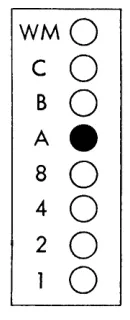
Another method of illustrating the same thing is shown in Figure 8. Circles represent the cores. If a core is on, the circle is shaded; all other cores are un-shaded and therefore are off.
WM
0
C
0
B
0
A
0
8
0
4
0
2
0
1
e
Figure 8.
Upon being read from the card into the 1401, every character (alphabetic, numerical or special) is con-verted from the IBM card code to the 1401's Binary
Coded Decimal and stored. With the binary coded decimal, the four lower cores, for values 1, 2, 4 or 8, are used singly or in combinations to represent the digits 0-9.
The on or off condition of a single core is referred to as a "bit" of information. Figure 9 illustrates the bit combinations used to represent each of the digits 0-9.
4
When reading the binary coded decimal, it is said that:
For the digit 1 the 1 bit is on. For the digit 2 the 2 bit is on.
For the digit 3 both the 1 and 2 bits are on, etc. For the digit 0 the 8 and 2 bits are on.
To see the codes as they appear in the 1401 re-quires an additional step. Note that in Figure 9 the A and B bits are off for all digits. Furthermore, the digits 1, 2, 4, 7 and 8 contain an odd number of on bits in the 1, 2, 4 and 8 positions. Each of the digits 3, 5, 6, 9 and 0 contains an even number of on bits in those positions.
Built into the machine is an automatic checking feature called the parity check. A character stored in the machine is checked each time it is moved from one location to another to make certain that it has an odd number of bits. In order to meet this test, the seventh core, labeled the C bit, or the check bit (see Figure 10), is automatically set on or off for each character being converted from the IBM card code to the binary coded decimal. As this conversion is made, a device in the 1401 counts the number of on bits in positions 1, 2, 4, 8, A and B. If the character con-sists of an even number of bits the C bit is set on; if the character consists of an odd number of bits the C bit is set off.
Thereafter, every time a character is moved any-where in the machine the parity check is proved. When any character fails to meet the odd bit count requirement, the machine stops processing immedi-ately. This is insurance against having characters changed after they enter the machine.
The digits 0-9 with the check bit added to the ap-propriate characters for the odd bit count are illus-trated in Figure 11.
Digits 3, 5, 6, 9 and 0 have a check bit in their respective storage positions. Without it, each would fail to pass the parity check. In addition, alphabetic and special characters must also meet the parity check.
With the binary coded decimal, alphabetic and special characters use the 1, 2, 4 and 8 bits for the numerical portion of the IBM card code, and A and
1
2
3
WMO
0
0
C
0
0
0
B
0
0
0
AO
0
0
80
0
0
40
0
0
20
e
e
1_
0
e
1
2
3
WMO
0
0
C
0
0
-B
0
0
0
AO
0
0
80
0
0
40
0
0
20
1_
e e
0
e
4
0
0
0
0
0
e
0
0
5
6
0
0
0
0
0
0
0
O·
0
0
e e
0
e
e
0
Figure 9.
WMO
C
e
B
0
AO
8
0
40
2
0
10
Figure 10. Storage Position
4
5
6
0
0
0
0
e
-0
0
0
0
0
0
0
0
0
e e
e
0
0
e
0
e
0
Figure 11.
7
8
9
a
0
0
0
OWM
0
0
0
Oc
0
0
0
OB
0
0
0
OA
0
e
e e
8
e
0
0
o
4
e
0
0
e
2
e
0
e
01
--7
8
9
a
0
0
0
OWM
0
0
e
_c
0
0
0
o
B
0
0
0
OA
0
e e e
8
e
0
0
o
4
e
0
0
e
2
The zero zone is represented by the A bit on.
WMO
C
0
BO
Ae
8
0
4
0
2
0
o
Figure 12. Zero Zone
The II zone is represented by the B bit on.
The 12 zone is
WMO
C
0
Be
AO
8
0
40
2
0
10
Figure 13. 11 Zone
represented by both the A and B bits on.
WMO
C
0
B
e
A
e
8
0
4
0
2
0
0
Figure 14. 12 Zone
Combining the bits representing zones, the bits rep-resenting digits, and any necessary check bit, alpha-betic and special characters appear as illustrated on the opposite page in Figure 15.
Core Storage Addressing in the 1401
The number of characters required to address each lo-cation varies with different types of machines. Some machines use a five-character address, others a four-character address, and still others a three-four-character address. The number of storage positions in the ma-chine affects, but does not necessarily determine, the number of digits required for addressing. The 1401 Card System uses a three-character scheme; therefore, each position of core storage has a three-character address assigned to it. The purpose of assigning an address to each position is the same as that of number-ing houses on a street - namely, to enable reference to a specific position. Storage positions are numbered consecutively. The address of the first position is 000; the address of the second, 001; the address of the third, 002; and so forth.
[image:10.612.161.226.86.246.2] [image:10.612.163.226.316.477.2]A 8
C
D E F G H I &.
t:lWMO
0
0
0
0
0
0
0
0
0
0
OWM
cO
0
•
0
• •
0
0
•
•
0
.c
8 .
• •
•
•
•
• • • •
•
• 8
A.
•
•
•
• • •
•
•
• •
.A
80 0
0
0
0
0
0
• •
0
•
• 8
40 0
0
•
• •
•
0
0
0
0
• 4
20
• •
0
0
• •
0
0
0
•
o
2
1.
0
•
0
•
0
•
0
•
0
•
01
J K L
M
N 0 P Q R-
$ *WMO
c.
0
0
0
0
0
0
0
0
0
0
OWM
•
0
•
0
0
•
•
0
0
•
OC
B.
• • •
•
•
•
•
• • •
• BAO
0
0
0
0
0
0
0
0
0
0
OA
80 0
0
0
0
0
0
• •
0
•
• 8
40
0
0
• •
•
•
0
0
0
0
• 4
20
1.
•
•
0
0
•
•
0
0
0
•
o
2
0
•
0
•
0
•
0
•
0
•
01
/
s
T U VW
X y Z+
I % /I @WMO
c.
0
0
0
0
0
0
0
0
0
0
0
0
OWM
•
0
•
0
0
• •
0
0
•
0
0
.c
B
0
0
0
0
0
0
0
0
0
0
0
0
0
o
8A.
•
• • •
• •
•
•
•
• •
0
OA
80 0
0
0
0
0
0
••
• • • • •
• 840 0
0
•
•
•
•
0
0
0
0
•
0
• 4
20
•
•
0
0
•
•
0
0
•
•
0
•
o
2
1.
0
•
0
•
0
•
0
•
0
•
0
•
01
Addressing
LOCATION -000-999 1000-1099 1100-1199 1200-1299 1300-1399 1400-1499 1500-1599 1600-1699 1700-1799 1800-1899 1900-1999 2000-2099 2100-2199 2200-2299 2300-2399 2400-2499 2500-2599 2600-2699 2700-2799 2800-2899 2900-2999 3000-3099 3100-3199 3200-3299 3300-3399 3400-3499 3500-3599 3600-3699 3700-3799 3800-3899 3900-3999 ADDRESS000-999 } +00-+99 /00-~99 SOO- 99 TOO-T99 UOO-U99 VOO-V99 WOO-W99 XOO-X99 YOO-Y99 ZOO-Z99 000-099
1
JOO-J99 KOO-K99 Loo-L99 MOO-M99 NOO-N99I
000-099 POO-P99 Qoo-Q99 Roo-R99 + + 000-099 AOO-A99 BOO-B99 Coo-C99 DOO-D99 Eoo-E99 FOO-F99 GOO-G99 HOO-H99 100-199 Figure 16.First character has no zone over digit
First character uses zero zone over digit
First character uses eleven zone over digit
First character uses twelve zone over digit
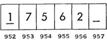
Since whole fields of information are stored more often than single characters, adjacent core storage posi-tions are thought of as "grouped" to form storage fields, in much the same way that card columns are grouped into card fields. Grouping of core positions changes from one application to another. A numerical field occupying storage positions 952-956, and contain-ing the value 17562, is illustrated in Figure 17. Posi-tion 952 is the high-order posiPosi-tion and 956 is the low-order position.
111
7
1
5
1
6
1
2 /
952 953 954 955 956
Figure 17.
Storage fields are defined to the machine with the aid of word marks. A word mark is recorded in the high-order storage position by using the topmost core in that position. (See Figure 18.)
8
WM
0
C
0
B
0
A
0
8
0
4
0
2
0
1
0
Figure 18.
If the topmost core is on, a word mark is said to be set in that storage position. (See Figur,e 19.)
WMe
C
0
BO
AO
8
0
4
0
2
0
o
Figure 19.
If the word mark core is off, there is no word mark in that position. Machine-coded instructions set and erase word marks; and can do so either before or during the processing of the application.
7
5
62
WM
e
0
0
0
0
c
e
0
e
-
0
B
0
0
0
0
0
A
0
0
0
0
0
8
0
0
0
0
0
4
0
- - -
0
2
0
-
0
-
e
1
e e e
0
0
952
953
954
955
956
Figure 20.
A storage field begins with the position containing the word mark and includes it and all other positions to the right, up to, but not including, the next posi-tion containing a word mark. In Figure 20, the amount field is composed of positions 952-956. The next field beyond the amount field begins in position 957.
From this point on, the presence of a word mark in a position of storage will be silgnaled by a line drawn under the character in that position. The pre-vious example now appears as:
952 953 954 955 956 957
Figure 21.
Positions 952 and 957 contain the word marks. A storage field can be either of two types - a data field or an instruction field. A data :field is one which contains information to be processed (such as sales amount), information to aid in processing (such as a control code), or information which is already proc-essed (such as an accumulated amount). Instruction fields contain coded instructions which the machine must execute in processing the data .. The size of the data field is determined by the greatest number of characters which can be in the data amount; the size of an instruction field is determined in the same man-ner.
-0
0
0
0
0
0
0
957
Variable Word Length
Certain stored-program machines, of which the 140 I is an example, have a desirable characteristic called "variable word length." The ability to have grouped together any number of storage positions to accom-modate fields of any size, gives rise to this term. The fact that a machine has variable word length allows efficient use of the storage area.
It is recalled that on both the 604 and 602 each storage unit contains a specific number of positions; each is fixed in length. For this reason, high-order positions are frequently wasted because, in size, the field is smaller than the unit.
In a variable word length machine this does not happen; there are no fixed groupings of storage posi-tions. Instead, the size of the grouping varies with the length of the data or instruction field to be ac-commodated. The word mark makes this possible; it can be set to make any storage position the high-order position. It can also be erased from storage positions when field limits change.
Other stored-program machines have "fixed word length." This means that storage positions are grouped and used in multiples of a constant number, generally multiples of ten positions. Each group of ten posi-tions, and the data in those posiposi-tions, is known as a "word."
Addressing Fields
[image:13.613.110.218.453.495.2]high-order pOSItIOn. The word mark in storage,
to-gether with an address found in the instruction, en-ables the machine to determine field limits.
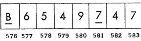
Word marks are always set in the high-order posi-tion regardless of type field. A data field is addressed in its low-order position. The machine then treats that position, and all successive positions to the left, up to and including the one containing the next word mark, as the data field.
576 577 578 579 580 581 582 583
Figure 22.
In Figure 22, if the digits in positions 576-580 rep-resent data, the field is addressed in its low-order posi-tion, 580. The machine uses the character stored in position 580 and all characters in successive locations to the left through position 576.
Instruction fields are addressed in their high-order position (the position containing the word mark). The machine treats that position and all positions to the right, up to} but not including, the next contain-ing a word mark, as becontain-ing part of the instruction field. If the digits in positions 576-580 of Figure 22 repre-sent an instruction, the field is addressed in position 576. Characters in all successive positions to the right, through position 580, are included as part of the in-struction.
Input-Output Areas
Every stored-program machine must have storage areas specified to the machine for the purposes of (1) read-ing in, (2) punching and (3) printing, if the machine performs all these functions. Otherwise, the machine, when instructed to read in, has no way of knowing where in the storage unit to put the card data; or, when instructed to punch, where in storage to gel the data it punches into the card; or, when instructed to print, where in storage to get the data for printing on the report.
Methods of specifying these areas are (1) wired cir-cuitry in the machine or (2) stored instructions in the machine. Each stored-program machine uses one of these types of input-output area specification.
10
Examples of machines which have input-output storage areas specified by internal circuitry are the 305, the 650 and the 1401. For example, on the 1401 during reading, the 80 columns of card data automati-cally go into storage positions 001-080 (see Iiigure 23) . The content of card column 1 goes into storage posi-tion 001, etc. When the 1401 is instructed to punch, it automatically punches into the card columns the contents of storage positions 101-180. If instructed to print, the 1401 automatically prints in the print posi-tions the contents of posiposi-tions 201-300 (or 201-332, de-pending upon the machine model) .
The fact that a storage area is used at one time for one of the input-output functions does not prevent its use for ordinary storage purposes at another time when that function is not being performed.
The Instruction
Instructions are the means of controlling a machine. All machines, wired control panel as well as stored-program, must be controlled to perform functions in the proper sequence, at the proper time, and with the proper data in order to process an application suc-cessfully. In stored-program machines this is accom-plished with the stored instruction. In wired control panel machines it is accomplished with the control panel.
In the 1401, an instruction has up to four parts:
1. The operation code (commonly referred to as the "op code")
2. The A / I address 3. The B address 4. The digit modifier
Each stored-program machine has a set of functions which it can perform, and for every function there is a corresponding op code. Each machine has its own set of operation codes.
The 1401 has single-character op codes. The codes are letters, numbers or special characters. For exam-ple:
A causes addition. 1 reads a card.
C compares two fields for control purposes. S causes subtraction.
[image:14.613.120.264.194.236.2]Read-in Area
A \
I I I
I I I
I I
000 001 080 081 099
Punch Area
A \
I I
I
I I I
I I
100 101 180 181 199
Print Area
I A I
I I I
I I
200 201 299
Print Area
I .A - - - " \
I
II
I I I
I
I
300 332 333 399
1fT
I I
400 499
I I I
!
500 599
I I I
'---~
The A/I address locates a field which is to be used or affected. It is generally the field from which data comes. The address always consists of three characters -the addressing scheme for the 1401.
The B address also locates a field to be affected or used when the machine performs the function speci-fied by the op code. This is generally the field to which data goes. This address, also, contains three characters.
The digit Dlodifier, used only with certain op codes, always consists of a single character. It adds power and flexibility to the op code.
An instruction containing an op code, an A address and a B address is:
OP
Code
A
A
Address
o
B
Address
9
This is an "add" operation. The op code, A, instructs the machine to add. The A address locates one of the fields to be used in the addition and the B ad-dress locates the other field to be used in the same op-eration. In this case the A address may represent sales amount coming into the machine from a card, and the B address may represent the accumulated amount of all sales cards up to this one.
After seeing this instruction, it is apparent that every instruction will not use all four components. The number of characters in the instruction is de-termined by the function being performed.
Examples of different combinations are: 1. Op code, I address, B address, digit modifier 2. Op code, A address, B address
3. Op code, I address, digit modifier
4. Op code, A/I address 5. Op code, digit modifier 6. Op code
Since the instructions can vary in length or in the number of characters contained, they are referred to as variable length instructions.
[image:16.621.128.273.249.317.2]A Comparison of Stored-Program Control and Wired-Panel Control
Figure 24 illustrates a 604 planning chart and Figure 25 a wiring diagram for crossfooting factors A, B, C
12
and D. The control panel wiring instructs the ma-chine as follows:
1. Read card columns 40-43 into general storage unit 4.
2. Read card columns 44-48 into factor storage unit 2.
3. Read card columns 49-52 into factor storage unit 4.
4. Read card columns 53-56 into general storage unit 2.
5. Read factor A out of general storage 4 and add it into the counter on program step 1.
6. Read factors B, C and D out of their respective storage units and add them into the counter on successive program steps.
7. Read out the sum T and reset the counter. T is punched in card columns 57-61.
To properly plan and diagram this problem for the
604 requires, among other things, a knowledge of con-trol panel hubs and the functions concon-trolled by these hubs. To properly plan and diagram the same prob-lem for the 1401 requires a knowledge of operation codes rather than hubs. The following chart illus-trates this principle of control by op codes vs. con-trol by concon-trol panel hubs. Crossfooting is the ex-ample. (Under the column headed "1401 Control," only the op code portion of the instruction is listed. For 604 control refer to the wiring diagTam in Fig-ure 25.)
FUNCTION 604 CONTROL 1401 CONTROL
1. Reading factors Accomplished by The op code 1 reads A. B. C. D. wires labeled 1. the entire card into storage positions 001-080.
+
2. Add factor A. Wires labeled 2. The op code 0 (plus
3. Add factor B toA. 4. Add factorC
to(A+B). 5. Add factorD
to(A+B + C). 6. Readout and
reset T. Punch T.
Wires labeled 6. Wires labeled 3.
Wires labeled 4. Wires labeled 5.
zero) resets a storage area for accumulation and adds factor A. The op code A causes addition.
The op code A causes addition.
The op code A causes addition.
OPERATION NOTES
READ
Miscellaneous Earnings + Regular Earnings + Extra Shift Earnings +
API'!.ICATION _Overtim~~~r?ngs = Gross Eart~~ PROBLEM A±Jt±-Q_ ·±!l_=T~ _______ . __ . ___ _
Punch
v1
I: :: I
:~ ~
I: :
~
: :
I
:::~I
H1
FH·:U~:&5
: :
I : : : :
'f:
I:~
Figure 24.
1
-:-rr-n~A~-~~-~'~~'~~
'r:. 'I';r3
P':r~/I;El;I~T~I:s
'rB '19
'rxD-;d~7~~;~--:~;~;:
3:~F:~T~~S1~t;5~E::~~~-3:~
;~-f - - 1 2' ]; .. ~ 6 7 " 9 10 C - c
B 0 0---0---0---0 • 0---0 0 - - 0
f - - - D p u - - - 12 12
~ _ _ _ _ _ _ _ _ ~ _ _ _ _ _ _ _ _ _ _ _ ---, 0---<>----0 0 0 0 0 0 0 0 0 0 0 0---0 0 - - 0
~~ BAL S!L~I:M~IAH PU 0-:, 0-:,
18
R 0
o 0 0
22
o 0 23
x 0 0 0 0 2S 25
y o o o o O O O O
BAl. TEST FOR SEl.PU
z ~20304C
~~~~P.:o
SUP ON PLUS PROG SUP PU0----0---0-- 1 0 2 0 3 0 .4 0
SUP ON MINUS DROP OUT
0----0---0-- 0 0 0 0
SUP WO BT SUP EXIT
0---0---0 0 0 0 0
- EMITTER CONTROL EE u~ ~ ~ ~ ~
fF T ~
G Ho
1
.0 8
'0
9
CD
Co 0 oNa 0 0 0 0' 0 0 oNe 0--;0 I 10--;01--_ _ _ _ ,
:: :frr:
0 0
~
: : :
:T~
c7! !c7
.-:-:--':.'
-.~,;-~",~,.-~
...
!.--~---~---~-,-i-;,~,.
::; ;::
0FIRST READING
Co a ONa 0 0 0 0 0 0 ONO ~l L~ "G 3E;I!'~ 0 C o o 0 0 0 0 0 0 C 0 ~ ~ ~ ~
T • 0----00 00--0
~R R~
. .
0--0
.
0--0DELAY
0--0
PU
~ r~ 0 0 ;;--;;PU~CHOSIEL~CT~RSo-o t o - O - ; ; - O -'~1
N 1. ' 2 J .4 N
o 0 0 0 0 0 0 0 0 0 0 0 0 0 0
~ 0 0 0 0 0 0 0 0 o. 0 0 0 0 0 ~
r s - - - ,
" 0 - ' -o - o ' ! -0'1-0-02 0 G~NE~Af ~TIO~~G~ E~T:-i~~---~--o -: 0 I
, - - - - · - - - C O U N T E R
EXIT-1 0 0 0 0 0 0 0 0
o 0 0
30
o 0 J5
o a 0 0 0 50 55
o 0
~ 0 0 a ~o a a 0 75
r
~ 0 0 0 ~PU~CHoSEll~CT~RS~ a ~-~I0 0 0 0 0 0 0 0 0 0 0 0 0
~.o 0 0 0 0 0 0 0 0 0 0 0 0 0 0 0 0 0 ~
r----o-~-o-o-o SE~ON~ R~AD~G--"-~O-O-~---20
H ~ o 0 0
.,
o 0 0 0 0
70 15 80 0 0 0 0 0 0 0 0 0 0 0 0 0 0 0 0 0
1 ' 0 - 0 - - 0 - 0 - 0 DOoU8l~ P~NC~ & ~lA~K ;Ol~MNo EN~RY~~- ~;"-o -~
I 0 0 0 D~UB~E P~NC;I &oSlAcNKoCO~UM~ E~IT~-o~~~
lo~:n:-:u:-:~~
_ _ _ _ _ _ _ _ _ _ _ _ _ _ _ ----1L _ _ _ _ _ _ _ _ _ _ _ _ ~ _____ ._, ___ _
Figure 25.
How Instructions and Data
Get into the Machine
After the application to be processed by the 1401 is chosen, it is planned thoroughly. Planning includes (1) analysis of the application, (2) planning and se-quencing steps to be used, (3) writing the instructions,
(4) designing storage (determining which areas will house data to be processed, data after it is processed, and instructions-keeping in mind the read-in, punch and print areas), and (5) testing the application.
In order to process the application, the machine must have stored inside it (1) the instructions which process the card data and (2) the card data to be processed. This requires two machine steps.
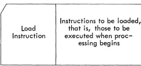
First the instructions are stored; this is termed "loading the program." This is equivalent to the in-sertion of a panel in wired control panel machines. In order to load the program, the instructions must already be in "program load cards" (see Figure 26). A program load card contains (1) instructions to be loaded and (2) load instructions which store in the proper area the instructions to be loaded.
Load
Instruction
Instructions to be loaded,
that is, those to be
executed when
proc-essing begins
Figure 26. Program Load Card
To load the program, the load cards are placed in the read hopper of the machine and the load button is de-pressed. After all the load cards are read, the pro-gram is loaded. The loaded instructions will be exe-cuted each time a data card feeds into the machine. They remain in storage until instructions for a dif-ferent routine replace them.
Processing of the application begins as soon as (1) the punched data cards are placed in the read hopper, (2) all units are readied, and (3) the start button is depressed.
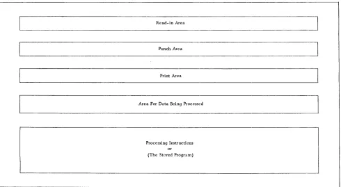
If storage could be seen once processing is begun (see Figure 27), there would be:
14
1. The read-in area containing the contents of a data card just coming in to be processed.
2. The punch area where information to be punched is assembled.
3. The print area where information to be printed is assembled.
4. The area necessary to hold data while it is being processed and before it can be put in one of the output areas.
5. The area containing instructions which are be-ing executed in order to process data and place it in the proper output areas.
[image:18.618.85.313.371.478.2]Read-in Area
Punch Area
Print Area
Area For Data Being Processed
Processing Instructions or (The Stored Program)
Figure 27. 1401 Storage
Planning is most important in putting an applica-tion into operaapplica-tion. The efficiency and output result-ing from a well planned application will compensate for the effort and time spent in planning and organ-izing the application. The ability to plan an appli-cation for a particular machine :requires an under-standing of the concept of the machine, the machine's components, the functions associated with the ma-chine, and the instructions which initiate these func-tions.
Planning a problem for the 14101 Data Processing System is very similar in principle Ito planning a prob-lem for the 602 or 604. In either case, the data which is available for input and the data desired as output must be known in order to bridge the gap between the two. The bridge represents machine processing; it consists of machine-coded instructions necessary to supply the missing data and to process all data in order to come up with the desired output.
Block Diagramming
Determining~ sequencing and expressing the neces-sary steps with a standard set of symbols constitutes block diagramming. It is the preliminary work for writing the machine-coded instructions.
Block diagramming is similar to completing the planning of a 602 or 604 problem. The machine must be instructed in each detail of operation. In Figure 24 is the planning chart for a crossfooting problem on the 604.
The planning chart illustrated in Figure 24 be-comes block diagramming by substituting the proper symbols. (See reference manual, Flow Charting and Block Diagramming Techniques, form C20-80OS.) Figure 28 is a block diagram of the same operation for the 1401 Data Processing System.
[image:19.612.57.547.118.387.2]Start
Read
A
Card 2
3
Reset And Add Factor A
4
Add Factor B
5
Add Factor C
6
Add Factor D
Punch T Into Card
7
8
A+B+C+D=T
Figure 28. Crossfootingand Punching Results
EXPLANATION OF FIGURE 28:
16
1. Start. - The card read punch and printer are readied and the start button is depressed. Start applies only for the first card.
2. For the first step a card is read into storage posi-tions 001-080.
3. For the second step certain positions of the stor-age punch area which are to be used for ac-cumulation are reset and factor A is added into them. On the 1401 it is necessary to reset the
ac-cumulate area before it is used; there is no op-eration code which will reset the area when T is read out.
4. For the third step factor B is added into the same area.
5. For the fourth step factor C is added into the same area.
6. For the fifth step factor D is added into the same area.
7. For the sixth step punching of the result, T, from storage positions 101-180 is initiated. 8. For the seventh step the machine is instructed
to go back to the first step, which causes the following card to be read and its processing be-gun.
Composing machine-coded instructions for each step in the block diagram is called programming. The ma-chine-coded instruction for the first step ("read a card") is 1. Each step thereafter has an instruction which will accomplish the operation indicated. It be-comes more obvious now why block diagramming is a preliminary for programming: the necessary steps must be determined before the coded instructions can be written. During block diagramming it should be kept in mind that there must be an instruction for every thing the machine is to do:
1. For causing each card to be read.
2. For moving data from the storage read-in area, and to and from the process area.
3. For performing arithmetic functions-add, sub-tract, multiply and divide.
4. For moving data to either the punch or print area.
5. For punching a card.
6. For printing each line of a report. 7. For form control.
Block diagramming can also be compared to flow charting. For both, a sequence of events is determined and recorded clearly and simply. The steps are then converted to machine instructions-stored-program in-structions or wired control panel inin-structions, which-ever is appropriate.
When the machine-coded instructions are written, the instructions become known collectively as the "program" or "routine."
[image:20.615.118.287.57.543.2]The 1401 Data Processilr'lg System
Components
The 1401 Data Processing System is a serial, vari-able word length, stored-program machine. It is con-trolled entirely by stored-program instructions; there are no control panels in any of the units.
Three units compose the 1401 Data Processing Sys-tem:
1. The 1401 Processing Unit. In it is found the cir-cuitry necessary to perform machine
functions-Section II
arithmetic operations, comparing, forms control, etc.; it also houses core storage and the console.
The console consists of (1) buttons and switches necessary to start routines, stop routines, test routines in the planning stages, and restart a routine after it is stopped; and (2) display lights which indicate the contents of storage positions and functions which are occurring.
18
2. The 140'2 Card Read Punch. All card reading and punching occurs in this unit. The reading occurs in the right-hand side at a maximum of 80'0' cards per minu teo Punching occurs in the left-hand side at a maximum of 250' cards per minute.
Cards to be read pass two sets of reading brushes. The first set of reading brushes is used for a checking function; the second set completes the check and allows the data to enter storage. On the punch side, cards first pass a set of punches where punching occurs and then a checking station where the punching is checked. Both feeds have a "pretest" station for sensing misfeeds. All card input and output is checked for validity. Invalid codes cause the machine to stop.
3. The 140'3 Printer prints at a maximum of 60'0' lines per minute and has a print span of 10'0' positions or 132 positions. Horizontal spacing is 10' characters per inch. Anyone of 48 charac-ters-26 alphabetic, 10' numerical and 12 special -can print in each print position. The twelfth special character is the
+
symbol or the record mark, depending upon the 140'1 model.Output to the printer is checked.
Vertical spacing can be six or eight lines to the inch and is under operator control.
Tapes
Up to six magnetic tape units can be alttached to the 140'1 Data Processing System. They can be either the 729 II or 729 IV.
1401 Storage
There is a maximum of 4,0'0'0' positions of core storage. Each position has a three-digit address.
Three areas of storage are reserved for specific pur-poses- (1) positions 0'0'1-0'80' for card read-in, (2) posi-tions 10'1-180' for punching, and (3) posiposi-tions 201-30'0'
(or 20' 1-332) for printing. When not used for these specified purposes, these areas may be used for any other purpose.
In the 140'1, characters are in the binary coded deci-mal; a parity check is performed for each character on every move.
Instruction Format and Operation Codes
The Instruction
The instruction format is:
OP
A/I
B
Digit
Code Address
Address
Modifier
X
XIXIX XIXIX
X
(Each x represents a character.)
1. The operation code always consists of a single character. It indicates the function to be per-formed.
2. The A or I address is always a three-digit ad-dress. A identifies a data field and I an instruc-tion field.
3. The B address is always a three-digit address. It always identifies a data field.
4. The digit modifier adds flexibility to the op codes with which it is appropriately used. Some instructions do not use all four parts. The ma-chine function to be performed determines which parts are used.
Operation Codes
Each of the following sections describes and illus-trates a group of operation codes'*'. The symbols I, A and B refer to type of address; "d" indicates the digit modifier.
(1) Word Mark Instructions
, - WORD MARK SET
OP
A
B
Code Address
Address
,
XIXIX XIXIX
This instruction may include one or two addresses, and will cause a word mark to be set at each of the specified addresses without disturbing data already there.
*For more information on the op codes described in this section, and others not described, refer to the General Information Manual for the 1401 Data Proc-essing System (form D24-140I) .
tI - WORD MARK. CLEAR
OP
Code
A
Address
B
Address
X
Same as WORD MARK SET except that word marks are cleared at the specified addresses.
(2) Input-Output Instructions
I-READ
OP
Code
This instruction stops the execution of instructions and reads a card. Then the execution of instructions continues. Contents of all eighty columns automati-cally go into storage positions 001-080.
2 - PRINT
OP
Code
2
This instruction stops the program, prints on the report the contents of the print area, and spaces the form. The print area includes positions 20'1-300 or 201-332.
3 - PRINT AND READ
OP
Code
3
This instruction combines the operations of READ
and PRINT. The program stops until printing and reading occur.
4-PUNCH
OP
Code
4
This instruction punches a card with the contents of the punch area (positions 101-180).
5 - READ AND PUNCH
OP
Code
5
This instruction combines the READ and PUNCH op-erations.
6 - PRINT AND PUNCH
OP
Code
6
This instruction combines the functions of PRINT
and PUNCH.
7 - PRINT, READ, PUNCH
OP
Code
7
This instruction combines the functions of READ,
PRINT and PUNCH.
(3) Move Operations
M-MOVE
20
OP
Code
M
A
Address
B
Address
x
This instruction causes the field at the A address to
be stored in the field at the B address, thus changing the contents of the B field.
Z - MOVE AND ZERO SUPPRESS
OP
A
Code Address
z
B
Address
x
This instruction is similar to the MOVE (M) instruc-tion except for one important difference: upon com-pletion of the operation, the B field will contain blanks, instead of zeros, to the left of the nlOst signifi-cant digit.
D - MOVE DIGIT
OP
A
Code Address
D
B
Address
This instruction causes the numerical portion only,
of the character in the storage position indicated by the A address, to be stored in the position indicated by the B address.
L - LOAD
OP
A
B
Code Address
Address
L
xlXlx Xlxlx
This instruction is the same as MOVE, except that
Y -MOVE ZONE
OP
Code
y
A
Address
B
Address
This instruction is similar to MOVE DIGIT, but only
the zone portion is moved.
(4) Arithmetic Codes
A-ADD
OP
Code
A
A
Address
B
Address
This instruction causes the field at the A address to add algebraically to the field at the B address.
S - SUBTRACT
OP
Code
s
A
Address
B
Address
This instruction causes the field at A address to be algebraically subtracted from the field at B address.
0-
RESET ADDOP
A
B
Code Address
Address
+
X X X X X X
0
This instruction is similar to the ADD instruction, except that the B field is set to zero before the A field data is added to it.
o -
RESET SUBTRACTOP
Code
o
A
Address
B
Address
B field is reset to zero before A field is algebrai-cally subtracted from it.
(5) Compare
c-
COMPAREOP
A
Code Address
C
B
Address
This instruction causes the field at the A address to be compared with the field at the B address.
The result of the compare (equal or unequal) is stored in the machine and then checked by a later instruction.
(6) Editing For Numerical Fields
E - EDIT
OP
A
Code Address
E
B
Address
Editing is the process of setting up numerical fields for printing. It allows control of symbol and zero printing. Two fields are needed - the data field and a control field. The data field contains only the in-formation to be printed. The control field specifies
(1) where commas, decimals, conditionalCR.. or minus symbols are to print, (2) where zero suppression is to stop, and (3) where characters from the data field are to print.
Figure 29 is an example of a data field.
Figure 29.
It is desired to print the data as it is illustrated in Figure 30, but with a CR between the last digit and
the asterisks if the amount is negative.
1$1
1~1'1517141·12161 1*
I*
Figure 30.
The control word to cause printing as illustrated in Figure 30 is:
~I,
Iblblol·lbHEEEJ
Figure 31.
IN FIGURE 31:
(a) Every character that is to print as itself (, $ ...
CR) is placed in the control word position which
corresponds to the position in which it is to print.
(b) Any position which should appear as a space during printing contains an & symbol.
(c) Any position representing a digit from the data field is blank in the control word. In Figure 31, b represents a blank.
(d) The rightmost position in which zero suppres-sion is to occur must have a zero.
Among other things editing accomplishes on the 1401 what zero print control and raised hammersplit levers accomplish on the 407 and 402-3 respectively.
(7) Test and Branch Instructions
Branch instructions accomplish on the 1401 what se-lectors accomplish on wired control panel machines. These instructions test for conditions which can arise during processing, such as negative balances, zero bal-ances, overflow, X or NX, control change, etc. If the condition tested for is in existence, this type instruc-tion causes the machine to skip from the regular in-structions to a group which handles that particular condition. Such an instruction must specify the ad-dress of the first instruction in the group. If the
con-22
dition tested for does not exist, the machine executes the next instruction in sequence.
Switching control from one instruction to another instruction which is not the next in sequence is called
"branching" or "a branch." The instruction which tests for a condition is a branch instruction.
Branch instructions take one of several forms: (a)
OP
I
Code Address
B
XIXIX
Always branch to the address indicated by I for the next instruction.
(b)
OP
I
Digit
Code Address
Modifier
B
xlxlx
X!
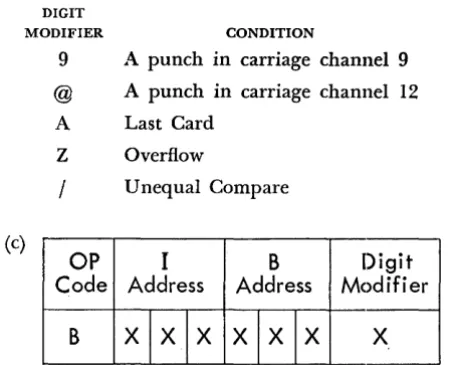
Program branch to the address indicated by I for the next instruction if the condition indicated by the digit modifier exists. Some of the digit modifier codes and the conditions for which they test are illustrated below.
DIGIT
MODIFIER CONDITION
9 A punch in carriage channel 9 @ A punch in carriage channel 12 A Last Card
Z Overflow
/
Unequal Compare(c)
OP
I
B
Digit
Code Address
Address
Modifier
B
XIXIX XIXIX
X [image:26.615.355.500.144.213.2] [image:26.615.345.529.265.335.2] [image:26.615.345.573.416.598.2](d) Another type instruction which accomplishes a test and branch operation is the "test for zone or word mark and branch." Its format is:
OP
I
B
Digit
Code Address
Address
Modifier
V
XIXIX XIXIX
X
1. The op code, V, identifies it as the "test for zone or word mark and branch" instruction.
2. The digit modifier identifies the type of test. Characters which can appear as digit modifiers, and the condition for which each tests, are illus-trated below.
DIGIT
MODIFIER CONDITION FOR WHICH IT TESTS
1 VVord ~ark
2 No zone (no A bit and no B bit) B 12 zone (A bit and B bit) K 11 zone (B bit and no A bit)
S Zero zone (A bit and no B bit) 3 Either a word mark or no zone C Either a word mark or 12 zone L Either a word mark or 11 zone T Either a word mark or zero zone 3. The B address is the storage portion which is
tested.
4. The I address is the location of the next instruc-tion to be executed if the condition exists. 5. If the condition does not exist the machine will
execute the next instruction in sequence.
(8) Miscellaneous Instructions
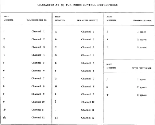
F - FORMS CONTROL
OP
Digit
Code Modifier
F
X
This instruction causes the carriage to move as specified by the digit modifier. In Figure 32 are digit modifiers which are used. Opposite each is the car-riage operation it will perform.
/ - CLEAR
OP
A
Code Address
/
XIXIX
This instruction is used to clear storage of data and word marks. It clears the position designated by the A address and all successively lower-numbered positions through 00 of that hundred. If the A ad-dress is 563, positions 563 through 500 are cleared. If
the A address is 599, positions 599 through 500 are cleared
N - NO OPERATION
OP
Code
N
This opera.tion code prevents the machine from doing anything for the instruction in which it ap-pears. The machine just executes the next instruction in sequence.
• - STOP
OP
Code
•
This instruction will cause the progranl to stop and the Stop Process light to turn on.
CHARACTER AT (d) FOR FORMS CONTROL INSTRUCTIONS
DIGIT DIGIT DIGIT
MODIFIER IMMEDIATE SKIP TO MODIFIER SKIP AFTER PRINT TO MODIFIER IMMEDIATE SPACE
I
1 Channel I A Channel 1 J 1 space
2 Channel 2 B Channel 2 K 2 spaces
3 Channel 3 C Channel 3 L 3 spaces
4 Channel 4 D Channel 4
5 Channel 5 E Channel 5
DIGIT
MODIFIER AFTER PRINT-SPACE
6 Channel 6 F Channel 6
7 Channel 7 G Channel 7 / 1 space
8 Channel 8 H Channel 8 S 2 spaces
9 Channel 9 I Channel 9 T 3 spaces
+
0 Channel 10 0 Channel 10
# Channel II
.
Channel 11@ Channel 12
t1
Channel 12I:
Figure 32.
[image:28.612.66.571.191.600.2]Section III
How Functions Associated with Wired Control
Panel Machines Are Accomplished on the 1401
Card Reading
Depression of the start key on the 1401 reads the first card automatically; thereafter, no cards are read un-less the machine executes a read instruction. The op code which initiates card reading is 1, and it appears in storage as:
Addition
OP
Code
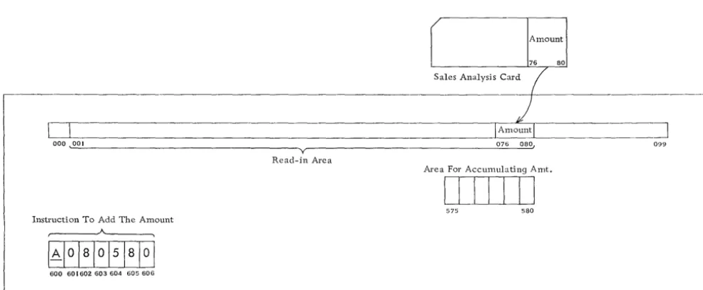
As illustrated in Figure 33, when a card is read, its contents automatically go to the read-in area, posi-tions 001-080. The amount (posiposi-tions 076-080 in this example) is to be accumulated. It can be accumulated
0
-ooo~
Y
Read-in Area
Instruction To Add The Amount A
IAl
oialol51aloi
600 601602603604 605606
in any available storage positions; positions 575-5'80 have been chosen.
The instruction to add the amount into position 575-580 is:
OP
A
B
Code Address
Address
A
olalo
51
a
l
o
-The op code, A, instructs the machine to add. -The A address, 080, identifies the card data field. The B address, 580, identifies the units position of the area for accumulation; an area for accumulation is the equivalent of a counter.
When the 1401 adds, the adding mechanism takes the factor indicated by the A address and the factor indicated by the B address, adds the two together and puts the sum of the two back in the B field.
The sales amount from the card remains in positions 076-080 until another card feeds in and replaces it.
r Amount
76 80
Sales Analysis Card
(
)
I Amountl
~
076 080, 099
Area For Accumulating Amt.
I
!
! !
I I I
575 580
__ J
Figure 33. 1401 Storage - Addition
[image:29.623.60.555.491.695.2]~ -~~--.-.~---.---,
Instruction To Subtract Expense Amt. From Budget Amt.
40040 I 402 403 404 405 406
Current Expense Amount
bIllTI
600 604L - -_ _ ~ _______ . _ _ ~_ ....
Current Budget Amount
I I I I I I
576 580
Figure 34. 1401 Storage - Subtraction. Current Budget Amount - Current Expense Amount = Current Over jUnder Budget
Subtraction
In Figure 34 appear the data fields and the instruc-tion in 1401 storage. Current Expense Amount (stor-age positions 600-604) is to be subtracted from Cur-rent Budget Amount (positions 576-580).
The 1401 instruction (positions 400-406) to subtract Current Expense from Current Budget Amount is:
OP
A
B
Code Address
Address
5
61
0
1
4
5[~_
-S is the subtract op code; the A address identifies the amount to be subtracted, and the B address identifies the factor from which it is subtracted. The machine subtracts Current Expense Amount (positions 600-604) from Current Budget Amount (positions 576-580) and places the difference, Current Over jUnder Budget, in positions 576-580.
Crossfooting
Figure 35 represents data factors and the instructions for crossfooting. OASI, federal withholding tax and VCI are crossfooted to give total deductions for each
employee.
Fed. OASI WjHold UCI
~-:---Rcod-in Ace"
~
]
c __________
~_~__
~___
~_ __J_~~_H_Ta_. x-'I_U_C_I-LI _ _ _ _ _0<>8 072 075
Crossfoot Instrilctions
400 402 404 406 408 410 412 414 416 418 420
ToLd Taxes
DIID
S76 580 [image:30.621.71.567.49.214.2] [image:30.621.73.566.424.696.2]The 1401 requires a series of program instructions to accomplish crossfooting just as a wired control panel accounting machine requires a series of program cycles. They are:
OP
A
B
Code Address
Address
1 •
+ 0 06 8
5 8
02.
A
07
2
5
8
0-3.
A
07 5 5
8
0-+
The first instruction, 0 068 580, resets to zero the accumulate area before adding OASI into positions
576-580. Instruction 2 adds federal withholding tax, and the third adds VCI. After the third instruction
is executed, total taxes are in positions 576-580.
Recognizing Negative Balances
The 1401 signals a negative balance by placing a credit X over the units position of the amount, as shown in Figure 36. (The X is a B bit.)
576 580
Figure 36. Negative Amount in HOI Storage
Instruction Which Tests Instruction To Be Exe-The Amount cuted If Amt. Is Positive
A A
401 408 409 415
In order to recognize a negative balance when it arises, a "test for zone and branch" instruction is exe-cuted. It tests the units position of the amount field for the X. The instruction is:
P
I
B
Digit
de Address
Address
Modifier
61
81
451
81
0K
-l. The B address indicates the units pOSItIOn, which is to be tested for the credit X.
2. The digit modifier, K, tells the ma€hine what to tes t for - a credit X.
3. The op code, V, instructs the machine that this is a "test for zone and branch" instruction. 4. The I address indicates the location of the next
instruction to be executed if the amount is nega-tive.
5. If the amount is positive, the next instruction executed will be the next one in succession. The instructions and the amount to be tested, as they appear in 1401 storage, are illustrated in Figure 37:
1. Positions 401-408 contain the instruction which tests the amount.
2. Positions 576-580 contain the amount to be tested.
3. Positions 409-415 contain the instructi