University of Huddersfield Repository
Brotherton, Mark
GPU Accelerated XRay Image Enhancement
Original Citation
Brotherton, Mark (2011) GPU Accelerated XRay Image Enhancement. Masters thesis, University
of Huddersfield.
This version is available at http://eprints.hud.ac.uk/id/eprint/11044/
The University Repository is a digital collection of the research output of the
University, available on Open Access. Copyright and Moral Rights for the items
on this site are retained by the individual author and/or other copyright owners.
Users may access full items free of charge; copies of full text items generally
can be reproduced, displayed or performed and given to third parties in any
format or medium for personal research or study, educational or notforprofit
purposes without prior permission or charge, provided:
•
The authors, title and full bibliographic details is credited in any copy;
•
A hyperlink and/or URL is included for the original metadata page; and
•
The content is not changed in any way.
For more information, including our policy and submission procedure, please
contact the Repository Team at: [email protected].
GPU Accelerated X-Ray
Image Enhancement
Mark James Brotherton
A thesis submitted to the University of Huddersfield in partial fulfilment of the requirements for the degree of Masters of Science by Research
The University of Huddersfield
2
Copyright Statement
i. The author of this thesis (including any appendices and/or schedules to this thesis) owns any
copyright in it (the “Copyright”) and s/he has given The University of Huddersfield the right
to use such copyright for any administrative, promotional, educational and/or teaching
purposes.
ii. Copies of this thesis, either in full or in extracts, may be made only in accordance with the
regulations of the University Library. Details of these regulations may be obtained from the
Librarian. This page must form part of any such copies made.
iii. The ownership of any patents, designs, trademarks and any and all other intellectual
property rights except for the Copyright (the “Intellectual Property Rights”) and any
reproductions of copyright works, for example graphs and tables (“Reproductions”), which
may be described in this thesis, may not be owned by the author and may be owned by third
parties. Such Intellectual Property Rights and Reproductions cannot and must not be made
available for use without the prior written permission of the owner(s) of the relevant
3
Abstract
This paper presents an automated method for preparing digital X-rays for use by a procedural mesh generator. This process will facilitate the generation of a 3D polygon mesh depicting the bones contained within the X-ray image. The process of preparing the image involves identifying and retaining bone elements whilst removing any superfluous aspects contained within the image, such as text and orientation markers. This will allow a virtual podiatric surgical simulator, VirtuOrtho to feature patient specific bone models generated from the processed X-rays. The algorithm additionally employs parallel processing techniques that are capable of utilizing either multi-core CPUs or a GPU to help to reduce the computational time required to process an image. The relative performance of the multi-core CPU implementation will be compared and contrasted to the performance of the GPU version. As part of the image processing algorithm, two GPGPU algorithms for median filter are proposed: a caching method improves upon the fast, small-radius median filter (McGuire, 2008) and a second method which uses a histogram based technique (Huang et al., 1979) to facilitate filters with large-radius masks to be processed using the GPU.
4
Acknowledgements
The author would like to thank to Andrew Boothroyd, Damian De Luca, Daniel Fitchie, Dr Duke
5
Table of Contents
Copyright Statement ... 2
Abstract ... 3
Acknowledgements ... 4
List of Figures ... 9
List of Abbreviations ... 13
Glossary ... 15
1. Introduction ... 21
1.1. Overview ... 21
1.2. VirtuOrtho ... 22
1.3. Problem Statement ... 23
1.4. Project Aims ... 26
1.4.1. Algorithm Objectives ... 26
1.4.2. Implementation Objectives... 27
1.4.3. Median Filter Objectives ... 28
1.4.4. Expected Results ... 28
2. Literature Review ... 30
2.1. Research Objectives ... 30
2.1.1. Parallel Processing ... 30
2.1.2. Image Processing and Analysis ... 31
2.2. Parallel Processing ... 32
2.2.1. Background ... 32
2.2.2. General-Purpose Computing on Graphics Processing Units ... 34
2.2.3. Parallel Processor Architectures ... 35
2.2.4. Parallel Algorithm Design ... 40
2.2.5. Parallel Processing APIs ... 45
6
2.3.1. Medical Imaging ... 51
2.3.2. Applicable Image Processing Techniques ... 54
2.4. Conclusions ... 59
3. Methodology ... 61
3.1. Overview ... 61
3.2. Implementation ... 61
3.3. Data Gathering ... 61
3.3.1. Algorithm Experiments ... 61
3.4. Results Analysis ... 63
4. Implementation ... 64
4.1. Overview ... 64
4.2. General Algorithm Description ... 64
4.2.1. Median Filter ... 65
4.2.2. Histogram and Image Thresholding ... 66
4.2.3. Sobel Edge Detection ... 68
4.2.4. Active Contour Model Feature Extraction ... 68
4.2.5. Threshold Mask ... 68
4.3. SISD Implementation ... 68
4.4. MIMD Implementation ... 68
4.4.1. Median Filtering ... 69
4.4.2. Histogram and Thresholding ... 70
4.4.3. Sobel ... 75
4.4.4. Active Contour Model Feature Extraction ... 75
4.4.5. Threshold Mask ... 76
4.5. SIMD Implementation ... 76
4.5.1. Median Filtering ... 76
4.5.2. Histogram and Thresholding ... 81
7
4.5.4. Active Contour Model Feature Extraction ... 82
4.5.5. Threshold Mask ... 83
4.6. Development Issues ... 83
4.6.1. Limited Data Types Available on GPU ... 83
4.6.2. Reduced Functionality in CS4.0 ... 83
4.6.3. Other Issues ... 84
4.6.4. Hardware Specific Optimisations ... 85
5. Results and Analysis ... 87
5.1. Overall Performance ... 87
5.2. Individual Component Performance ... 88
5.3. Data Format Performance ... 90
5.4. Median Filtering Performance ... 91
5.5. Optimum Number of Threads ... 94
5.6. Average Image Error ... 96
5.7. Image Comparison ... 97
6. Conclusions ... 103
6.1. Overview ... 103
6.1.1. Individual Project Aims ... 103
6.2. Parallel Processing ... 104
6.2.1. Multi-core CPU ... 104
6.2.2. GPGPU ... 105
6.3. Algorithm ... 107
6.4. Summary ... 107
7. Future Work ... 108
7.1. Active Contour Model Feature Extraction ... 108
7.2. GPU Median Filter ... 108
7.3. X-Ray Header Information ... 109
8
7.5. Generating Skin Mesh ... 110
7.6. Parallel Mesh Generation Pipeline. ... 110
7.7. Benchmarking ... 110
7.8. Alternative GPGPU Implementations ... 111
8. References ... 112
9. Appendices ... 119
9.1. Appendix A: Hardware Statistics ... 119
9.2. Appendix B: Test Hardware ... 121
9.3. Appendix C: YEF Proposal ... 122
9.4. Appendix D: Performance Results Data ... 125
9.4.1. Overall Execution Time ... 125
9.4.2. Individual Component Execution Time ... 125
9.4.3. Data Format Performance ... 126
9.4.4. Median Filter Performance ... 126
9.4.5. Optimum Number of Threads ... 127
9.5. Appendix E: Source Code ... 128
9.5.1. DirectCompute Fast, Small-Radius Median Filter ... 128
9.5.2. GPU Histogram Median Filter ... 129
9.5.3. GPU Sobel Filter ... 130
9.6. Appendix F: Compute Shader Functionality ... 131
9
List of Figures
Figure 1 : VirtuOrtho ... 22
Figure 2 : SensAble PHANTOM® Omni ... 23
Figure 3 : Lateral Foot X-ray (Original) ... 24
Figure 4 : Lateral Foot X-ray with Unwanted Elements Highlighted ... 25
Figure 5 : Planar Foot X-Ray (Original) ... 25
Figure 6 : Planar Foot X-Ray with Unwanted Elements Highlighted ... 26
Figure 7 : Intel Core i7 Multi-core CPU Architecture ... 36
Figure 8 : AMD HD 5870 GPU Architecture ... 38
Figure 9 : Nvidia GeForce GTX 580 GPU Architecture ... 39
Figure 10 : GPU Branch Operation ... 40
Figure 11 : Amdahl's Law ... 43
Figure 12 : Dispatch Call ... 49
Figure 13 : Proposed Method for Processing an X-ray Image ... 64
Figure 14 : Anticipated Algorithm Output ... 65
Figure 15 : Typical X-Ray Image Histogram ... 67
Figure 16 : X-ray Image Histogram with Secondary Background ... 67
Figure 17 : Mask Overlaps between Neighbouring Pixels ... 78
Figure 18 : Caching 3x3 Median Filter Diagram ... 79
Figure 19 : Algorithm Performance Results ... 87
Figure 20 : Individual Component Performance Results (Overall) ... 89
Figure 21 : Individual Component Performance Results (In Detail) ... 89
Figure 22 : Data Format Performance ... 91
Figure 23 : Median Filter Performance Results ... 92
Figure 24 : Median Filter Performance Results (Large-radius) ... 93
Figure 25 : Optimum Number of Threads ... 95
Figure 26 : Algorithm Final Output - Integer (Lateral) ... 97
Figure 27 : Algorithm Final Output - Float (Lateral) ... 98
Figure 28 : Image Differences Integer CPU – Integer GPU (Lateral) ... 98
Figure 29 : Image Differences Integer – Floating Point (Lateral) ... 99
Figure 30 : Algorithm Final Output - Integer (Planar) ... 99
Figure 31 : Algorithm Final Output - Float (Planar) ... 100
Figure 32 : Image Differences Integer – Floating Point (Planar) ... 100
11
List of Tables
Table 1 : Source Code Formatting ... 12
Table 2 : Flynn's Taxonomy ... 33
Table 3 : Overall Algorithm Speedup ... 87
Table 4 : Individual Component Speedup ... 90
Table 5 : Median Filter Speedup ... 94
Table 6 : Number of Errors ... 96
Table 7 : Steam Hardware Survey, Number of CPU cores ... 119
Table 8 : Steam Hardware Survey, Advanced CPU Feature Support ... 119
Table 9 : Steam Hardware Survey, DirectX 11 Graphics Cards ... 120
Table 10 : Test Hardware Configuration ... 121
Table 11 : Visual Studio 2010 C++ Compiler Settings ... 121
Table 12 : YEF Funding Application Form... 122
Table 13 : Overall Execution Time... 125
Table 14 : Individual Component Execution Time ... 125
Table 15 : Data Format Performance ... 126
Table 16 : Median Filter (3 x 3) Performance ... 126
Table 17 : Median Filter (19 x 19) Performance ... 126
Table 18 : Optimum Number of Threads (Median) ... 127
Table 19 : Optimum Number of Threads (Sobel) ... 127
12
List of Equations
Equation 1 : AMD HD 5770 Processing Cores ... 39
Equation 2 : nVidia GTX 580 Processing Cores ... 39
Equation 3 : Amdahl's Law – Overall Speedup ... 42
Equation 4 : Amdahl's Law - Speedup ... 42
Equation 5 : Gustafson's Law ... 43
Equation 6 : Parallel Speedup ... 44
Equation 7 : Maximum Speedup ... 44
Equation 8 : Parallel Algorithm Efficiency ... 44
Equation 9 : Calculating Parallel Portion ... 53
Equation 10 : Amdahl’s Law for HyperThreading ... 53
13
Code Listings
Code Listing 1 : OpenMP Loop Declaration ... 46
Code Listing 2 : Example DirectCompute Shader... 48
Code Listing 3 : DirectCompute Dispatch Function ... 50
Code Listing 4 : Histogram Based Median Filter Algorithm ... 55
Code Listing 5 : Sorting Based Median Filter Algorithm ... 56
Code Listing 6 : OpenMP Synchronisation Constructs ... 69
Code Listing 7 : OpenMP Median Filter ... 70
Code Listing 8 : OpenMP Reduction Operation ... 71
Code Listing 9 : OpenMP Histogram Calculation ... 72
Code Listing 10 : OpenMP Histogram Calculation via Atomic Operations ... 73
Code Listing 11 : OpenMP Threshold Operation ... 74
Code Listing 12 : OpenMP Sobel Filter ... 75
Code Listing 13 : Compute Shader 5.0 Caching Median Filter ... 80
Code Listing 14 : HLSL Median Calculation ... 81
Code Listing 15 : GPU Threshold Filter ... 82
Code Listing 16 : Compute Shader 4.0 Caching Median Filter ... 85
Code Listing 17 : GPU Fast, Small-Radius Median Filter ... 128
Code Listing 18 : GPU Histogram Median Filter ... 129
Code Listing 19 : GPU Sobel Filter ... 130
Source Code Formatting
Note: The source is written in C++ or HLSL.
Table 1 : Source Code Formatting
Format Notes
Line Number 1: If a line of code is longer that the available space, it will wrap beneath and not have a line number.
Data Types int variable Intrinsic Functions if(value) Compiler Directives #define
Comments //Comment
Array Operator array[index]
14
List of Abbreviations
2D: Two Dimensional
3D: Three Dimensional
AAM: Active Appearance Model
ACM: Active Contour Model
API: Application Programming Interface
ALU: Arithmetic Logic Unit
ASM: Active Shape Model
AVX: Advanced Vector Extensions
CPU: Central Processing Unit
CS4.0: Compute Shader 4.0
CS5.0: Compute Shader 5.0
CT: Computed Tomography
CUDA: Compute Unified Device Architecture
DICOM: Digital Imaging and Communications in Medicine
Float: Single Precision Floating Point
GPU: Graphics Processing Unit
GPGPU: General-Purpose computing on Graphics Processing Units
HLSL: High Level Shading Language
HT: HyperThreading
half: Half Precision Floating Point
int: Signed Integer
15 L2: Level 2
L3: Level 3
MIMD: Multiple Instruction Multiple Data
MISD: Multiple Instruction Single Data
MRI: Magnetic Resonance Imaging
OS: Operating System
PS: Pixel Shader
R16F: Red 16bit Float
R32F: Red 32bit Float
RAM: Random Access Memory
SIMD: Single Instruction Multiple Data
SISD: Single Instruction Single Data
SSE: Streaming SIMD Extensions
uint: Unsigned Integer
ushort: Unsigned Short Integer
16
Glossary
Active Appearance Model (AAM): Active Appearance Models are an improvement ASM method of feature extraction. Like ASMs they track contours but also use the texture surrounding the contours
to reduce the number of landmarks required.
Active Contour Model (ACM): Active Contour Models or “Snakes” is a method of feature extraction that tracks contours contained in an image by moving a set of points until they enclose the target
feature.
Active Shape Model (ASM): Active Shape Models are an improvement of the popular ACM method of feature extraction. ASMs locate objects by being trained using a number of images with marked
landmark points covering the possible shape variations.
Advanced Vector Extensions (AVX): Advanced Vector Extensions is an improved version of the SSE instruction set, capable of processing larger amounts of data (256 bits instead of 128 bits) and
instructions with 3-operands rather than 2-operand instructions available with SSE.
Application Programming Interface (API): An API is an interfacewhich a program can use to obtain access to functionality provided by procedures, functions and classes from either the operating
system or another application.
Arithmetic Logic Unit (ALU): The Arithmetic Logic Unit is the part of a processor that performs arithmetic and logic operations on data. The individual processing cores of a GPU’s SIMD engine are
typically referred to as ALUs.
Atomic Operations: Is an operation that is executed in such a manner that only a single thread can alter the item of data at a time.
Benchmarking: Benchmarks are designed to measure the real-world computational performance of a given system by mimicking the typical workload a system is expected to perform.
C: Is a procedural, high level programming language.
C++: Is an object oriented, high level programming language based on the C language.
Cache Memory: Cache memory is a type of high speed memory that can be used to store frequently used data, so that it can be retrieved without having to access main memory. In consumer hardware
17
Note: For the purposes of this report, the term cache will be used to refer to cache memory contained in each SIMD engine in the case of a GPU and Shared Level 3 Cache Memory in CPUs, unless otherwise stated.
Central Processing Unit (CPU): The CPU is a general purpose processor in a computer which controls all other systems in the computer.
Compute Shader: A GPU program for performing calculations on general data rather than vertices or pixels. It is currently available as two main versions, CS4.0 for DirectX 10 compliant hardware and
CS5.0 which contains additional functionality and other enhancements for DirectX 11 GPUs.
Compute Unified Device Architecture (CUDA): CUDA is a GPGPU API developed by nVidia; it is programmed in a C Style language. It currently only supports certain models of nVidia Graphics Cards
(NVIDIA, 2010b).
Computed Tomography (CT): A technique that is capable of generating a volumetric (3D) image of an object using a series of two-dimensional X-ray images taken about a single axis.
Core: A core is the part of the processor that is capable of reading and executing instructions on data. A single-core processor can process and execute only one instruction at a time, whereas a
multi-core processor can execute one instruction per core.
Note: For the purposes of this report, the term core or processing core will be used to refer to a single physical processing unit in the context of CPUs. When used in the context of GPUs it will be used to refer to a single processor within a SIMD engine.
Digital Imaging and Communications in Medicine (DICOM): DICOM is a file format for storing Digital Medical Images including X-rays, MRI and CT scans.
DirectCompute: Microsoft's DirectCompute is a GPGPU API available as part of the DirectX 11 package of APIs. Programs written with the API can be executed by DirectX 10 and 11 compliant
graphics processors.
DirectX: DirectX is a collection of APIs for handling game programming and other related tasks. It provides capabilities for 3D graphics rendering, audio and video amongst others. The latest version
of DirectX is version 11 but version 9.0c is still very popular amongst game developers.
General-Purpose computing on Graphics Processing Units (GPGPU): A technique for utilising the processing capabilities of the Graphics Card to process general computing problems rather than the
18 Global Memory: This term is used to distinguish between the “main” random access memory incorporated into a GPU and the cache memory available to each thread group. The term “global
memory” is used specifically in the context of GPUs and does not refer to the “main” random access
memory of the computer.
Graphics Card: See Graphics Processing Unit.
Graphics Processing Unit (GPU): The GPU is a specialised processor primarily designed for accelerating graphics related data processing to provide real-time 3D rendering.
Haptics: Is a technology used provide to tactile feedback to a user by the application of forces, vibrations, and/or motions.
High Level Shading Language (HLSL): HLSL is a C style programming language used to create shaders for use with Microsoft’s DirectX API, including Compute Shaders.
Histogram: A histogram is an array of numbers (bins), where each bin corresponds to the frequency count of a range of values contained within an image associated with that particular bin.
Instruction Set: An instruction set is a list containing all the instructions a processor compliant with that particular instruction set can execute.
Integer (int): A data type available in C++ which is used to store integer values using 32bits of memory. It is capable of storing a whole number value between -2,147,483,648 and 2,147,483,647.
Magnetic Resonance Imaging (MRI): Is a medical imaging method used to visualize internal structures in great detail. It especially useful in producing images of the brain, muscles, heart, etc.
compared with other medical imaging techniques such as X-rays.
Mesh: A polygon mesh is a collection of vertices, edges and faces that define a polyhedral object in 3D computer graphics.
Multi-core: Multi-core is a term typically used to describe CPUs which contain more than one processing core.
Multiple Instruction Multiple Data (MIMD): Is a parallel processing architecture which has a number of processors that are capable of functioning asynchronously and independently of each other. The
data and instructions being processed by a particular processor does not necessarily have to be
19 Multiple Instruction Single Data (MISD): Is an uncommon parallel processing architecture which executes multiple instructions simultaneously on a single item of data, typically it is used for fault
tolerant computing.
Open Computing Language (OpenCL): OpenCL is designed to be a platform independent implementation of a GPGPU API.
Open Graphics Language (OpenGL): Is a cross-language and cross-platform API for writing applications that produce 2D and 3D computer graphics. It fulfils the same roles as the Direct3D API
does in DirectX
Open Multi-Processor (OpenMP): OpenMP is designed to be a platform independent API which provides a lightweight method of processing data in parallel on multi-processor systems.
Pixel Shader: A GPU program for performing calculations on pixels. It is typically used to calculate the colour and any lighting effects on a 3D mesh.
Polygon: A polygon is the basic building block for constructing 3D meshes in computer graphics. It is a triangular surface and contains three vertices describing the location of its corners.
R16F: A texture format that has a single 16bit floating point value red colour channel.
R32F: A texture format that has a single 32bit floating point value red colour channel.
Random Access Memory (RAM): Is a type of memory that can retrieve a piece of data in a constant time, regardless of its physical location in memory. RAM is also referred to as “Main Memory”
Salt and Pepper Noise: Salt and Pepper noise manifests itself as random speckles within an image.
Scalar Processor: A processor architecture can execute a single instruction on a single item of data at once.
Shader: A program designed to be executed on a GPU, typically used for lighting calculations.
Shader Model: The shader model specifies what HLSL instruction set is supported by the GPU. The lowest and most restrictive model being Shader Model 1, with Shader Model 5 currently being
highest and most feature rich.
20 Hardware vendors use different terminology when referring to SIMD processors. AMD use the term
SIMD engine whilst Nvidia uses CUDA Cores.
Note: For the purposes of this report, the term “SIMD engine” will be used when referring to SIMD processors for both hardware vendors, as AMD GPUs are the main focus of this report.
Single Instruction Multiple Data (SIMD): A parallel processing architecture that performs the same operation on multipleitems of data at the same time.
Single Instruction Single Data (SISD): A parallel processor architecture that can execute a single instruction on a single item of data at a time.
Single Precision Floating Point (float): Is a data type available in C++ which is used to represent fractional values. It is capable of storing a fractional value between ±1.5 × 10−45 to ±3.4 × 1038 with 7
digits of precision.
Streaming SIMD Extensions (SSE): Is a SIMD instruction set used to expedite certain operations on a CPU.
Texture: In computer graphics a texture is an image that is mapped onto a polygon mesh.
Thread: A thread is a part of a computer program comprised of a single sequence of instructions which can be execute independently to other parts of a computer program. A group of threads can
be executed in parallel by a multi-core processor.
Thread Group: The term refers to a group of threads which are executed by the same SIMD engine in parallel on a GPU. Threads within a thread group can be synchronised and have access to a shared
region of cache memory.
Three Dimensional (3D): A Three Dimensionalobject in computer graphics has depth information. Typical 3D objects in computer graphics are polygon meshes and volumetric models.
Two Dimensional (2D): A Two Dimensionalobject in computer graphics is flat and contains no depth information. Typical 2D objects in computer graphics are images and fonts.
Unified Shader Architecture: The unified shader architecture or stream processing replaced separate vertex and pixel shader processors with a processor that was capable of processing both
data types.
21 Unsigned Short Integer (ushort): A data type which can store a whole number value between 0 and 65,535 using 16bits of memory.
Vector Processor: Is a processor architecture that is capable of executing a single instruction on multiple items of data in a single operation.
Vertex/Vertices: In computer graphics a vertex describes one of the three corners of a triangular surface (or polygon).
Vertex Buffer: A Vertex Buffer is a memory location for storing mesh vertices relating to a particular mesh. The vertices are stored in the most efficient manner for the GPU to process them.
Vertex Shader: A GPU program for performing calculations on vertices. It is typically used to transform vertices to their correct location and orientation in a 3D environment.
Video Memory: Video memory is a term used to differentiate between the “main” random access memory of a computer and the specialised RAM incorporated into a GPU.
Voxel: A Voxel is a cube shaped object which represents a point in 3D space, similar to a pixel in 2D space.
22
1.
Introduction
1.1.
Overview
This report details an algorithm that will be capable of providing an automated method for preparing
digital X-rays for use by a procedural mesh generator. The mesh generator will construct a three
dimensional (3D) polygon mesh from a number of X-ray images processed using the algorithm. This
mesh will subsequently be used to provide a patient specific bone model in VirtuOrtho, a virtual
surgical simulator. The algorithm will prepare the X-ray image by identifying and retaining areas of
interest (bone) whilst removing any superfluous aspects contained within the image including text,
orientation markers and backgrounds. Noise reduction techniques will be employed to suppress any
noise present in the image. This will ensure that the mesh generated from the processed X-rays will
have sufficient accuracy for the purposes of the simulation.
The proposed algorithm requires the processing of a considerable quantity of data and as a result
this will have an impact on the time required to execute the algorithm. A significant portion of this
computation could potentially be performed in parallel, minimising the time required to process an
image. Therefore techniques which allow the algorithm to exploit the parallel processing capabilities
of either a multi-core CPU or a GPU will be employed. Additionally the relative performance of the
multi-core CPU implementation will be compared and contrasted to the performance of the GPU
version.
As part of the GPU version of the algorithm, two methods for accelerating the calculation of a
median filter using a GPU are suggested. The caching method improves upon the fast, small-radius
median filter (McGuire, 2008) by utilising the cache memory provided in the latest generation of
consumer graphics cards. The second technique uses the cache memory to implement a histogram
based (Huang et al., 1979) method for applying median filters this enables the GPU to process
23
1.2.
VirtuOrtho
Figure 1 : VirtuOrtho
The functionality provided by VirtuOrtho can be broken down into a number of components. The algorithm proposed in this report relates specifically to the enhancement of X-ray images in preparation for their use by the mesh generator, which is being developed separately.
VirtuOrtho is intended to be a virtual surgical simulator for use as part of a training regime for
trainee podiatric surgeons. The software will utilise a SensAble PHANTOM® Omni haptic input device
as the primary input method during the virtual surgery. The device's capabilities (SensAble
Technologies, 2010) enable the software to feature accurate, real time tracking of user input in three
dimensions. It also provides haptic force feedback effects, which will be used to mimic the forces felt
by the surgeon whilst performing a surgical procedure. The software will procedurally generate a 3D
polygon mesh of the bones within a patient's foot by analysing a set of digital X-ray images taken at
a number of predefined angles1. The use of a procedural mesh generator enables the incorporation
of patient specific bone models into the virtual environment, allowing the training to be tailored to
suit a particular operation. An additional benefit is that this also will greatly reduce the complexity of
reproducing a range of afflictions, enabling VirtuOrtho to replicate the corresponding surgical
procedure. To further enhance the realism of the training environment provided by VirtuOrtho, it
will incorporate support for a 3D stereoscopic monitor which offers the user improved depth
perception within the virtual environment.
1
Currently only X-rays taken at lateral and planar orientations are used.
Virtual Surgery X-Ray Image
Capture
Mesh Generation X-Ray Image
Enhancement
24
Figure 2 : SensAble PHANTOM® Omni
The SensAble PHANTOM® Omni is a haptic input device capable of tracking user input and providing force feedback in 3 dimensions.
1.3.
Problem Statement
VirtuOrtho requires a number of polygon meshes depicting a variety of afflictions, so that it is
capable of simulating a broad range of surgical procedures which occur in Podiatric Surgery. Typically
these meshes are created by a digital artist using 3D modelling software such as 3Ds Max. This can
be a time consuming and expensive process. Due to the intricate and highly detailed nature of the
meshes required, it is realistic to assume that they may contain a number of inaccuracies, which
would in turn affect the usefulness of the simulation. The inclusion of a procedural mesh generator
into VirtuOrtho would eliminate the need for a digital artist to create the mesh, negating the cost
issues mentioned. Procedurally generated meshes should contain fewer inaccuracies because they
can utilise the maximum precision of the X-ray image and it reduces the chance that errors may be
introduced. However, a process of determining the accuracy of both a procedurally generated and a
handmade mesh would have to be devised. An additional benefit is that this would allow the
software to incorporate patient specific meshesrather than a generic mesh for each affliction.
Consequently this would make the software a more comprehensive and therefore useful training
tool.
The mesh generator must construct a polygon mesh using 2D digital X-rays rather than a 3D scan
such as those obtained using MRI or CT imaging. This is because 3D imaging techniques are rarely
used in Podiatric Surgery, primarily due to X-rays being the most cost effective method of creating
an image which contains all the pertinent information required to perform a surgical procedure.
From a software development standpoint a CT scan or similar 3D imaging technique would provide a
much simpler basis from which to generate a 3D polygon mesh, as it contains three dimensional data
(FAKULTI KEJURUTERAAN ELEKTRIK, n.d., p.2). A CT scan is able to achieve this because unlike a
25 dimensional data would allow the implementation of either an iso-surface extraction technique (JaJa
et al., 2008) or a voxel based system (Jeong et al., 2007). A voxel based representation as an
alternative to a polygon mesh greatly simplifies the generation process, however there is a
considerable increase in the computational cost for the visualization of the 3D model compared to
polygon meshes.
The images contained within digital X-rays are monochrome, typically stored as 12bit brightness
values. The properties of X-ray radiation which is used to capture X-ray images means that the
density of a material affect its brightness, with high density materials like bone being brighter than
materials with a low density such as soft tissue. This is not a uniform brightness, as the relative
distance of the material from the capture device also affects its brightness2. Salt-and-pepper noise
(Myler and Weeks, 1993, p.202) occurs in X-ray images due to the imprecise nature of the radiation
which is used to capture an X-ray. X-ray images may also contain the following superfluous elements
which need to be removed before the X-ray can be used by the mesh generator [Figure 4, Figure 6]:
text, orientation markers, rulers and secondary backgrounds. Removing these would result in a more
[image:26.595.124.472.392.668.2]accurate mesh being generated.
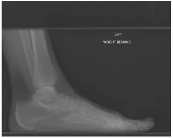
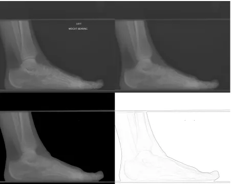
Figure 3 : Lateral Foot X-ray (Original)
The above image shows the original lateral image encoded in the DICOM file.
2
26
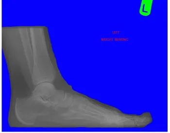
Figure 4 : Lateral Foot X-ray with Unwanted Elements Highlighted
This image highlights those unwanted elements contained within the X-ray image which need to be removed by the algorithm. Blue is the primary background, Red is descriptive text and Green is the orientation marker.
Figure 5 : Planar Foot X-Ray (Original)
[image:27.595.150.447.437.660.2]27
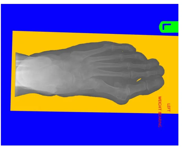
Figure 6 : Planar Foot X-Ray with Unwanted Elements Highlighted
This image highlights those unwanted elements contained within the X-ray image which the algorithm needs to remove. Blue is the primary background, Yellow the secondary background, Red is descriptive text and Green is an orientation marker
1.4.
Project Aims
It is the aim of this project to produce an algorithm that is capable of removing unwanted features
such as text and orientation markers from a digital X-ray whilst retaining areas of interest such as the
various bones contained within the image. This algorithm should be developed so that it is capable
of making optimal use of a parallel processor such as a multi-core CPU or a GPU. It is hoped that by
adopting parallel processing techniques, the algorithm will have a considerably reduced execution
time in comparison to a serial CPU implementation. The images processed by the algorithm will
subsequently be used to generate a 3D mesh replicating the bones depicted within the X-ray images.
The mesh generation and virtual surgery functionality of VirtuOrtho are being developed separately.
The objectives for this project have been split into two distinct categories, those objectives which
directly relate to the capabilities of the algorithm and those which affect its implementation.
1.4.1. Algorithm Objectives
1. Separate Soft Tissue and Bone: The algorithm requires the ability to accurately identify and subsequently isolate soft tissue and bone within an X-ray image. Ideally the algorithm will also
28 2. Remove Unwanted Features: Generally X-rays contain unwanted features [Figure 4, Figure 6] such as text, various backgrounds and orientation markers. These need to be removed from the
image to simplify the mesh generation process.
3. Noise Reduction: Appropriate techniques should be employed to diminish the amount of noise present within the X-ray image, on the condition that it does not negatively impact the fine
details stored in useful areas of the image.
4. Planar and Lateral X-Rays: The algorithm must be capable of adapting to compensate for the differences between X-rays taken at lateral and planar orientations. This will allow it to correctly
process images irrespective of their capture orientation. The mesh generator is currently limited
to constructing polygon meshes utilising only X-rays captured in planar and lateral orientations.
However it is envisioned that additional orientations will be used to increase the accuracy of the
generated mesh. Therefore, if possible it should also be capable of processing X-rays taken at
additional intermediate angles.
5. Non-Uniform Brightness: Due to the method by which X-ray images are created, some bones, particularly those at the extremities, are of a significantly lower brightness than other areas of
bone. The algorithm must therefore be able to recognise this and adapt accordingly.
1.4.2. Implementation Objectives
1. DICOM X-Rays: In-order to help ensure that the mesh generation process is as straightforward and seamless as possible for the end user; the algorithm should be capable of processing digital
X-ray images in their native file format (DICOM file). This will allow VirtuOrtho to generate a
patient specific model in the simplest manner possible, requiring only the location where the
X-rays are stored on the computer.
2. Fully Automated: VirtuOrtho is designed as a training tool; the algorithm should therefore require minimal human input wherever possible.
3. Consumer Hardware: The algorithm must be restricted to utilising only parallel processing technologies that are available in current consumer hardware. This will help to minimise the
cost of purchasing hardware for the client.
4. Single Instruction Single Data Implementation: The algorithm will need to be implemented as a serial process for the CPU in addition to the proposed parallel versions. This implementation
will be used to provide a control group in the performance comparison experiments and
therefore will serve as the baseline execution time for the algorithm on a given X-ray image.
This will be used in the calculation of the potential speed-up derived from parallelising the
process.
29 5. Multiple Instruction Multiple Data Algorithm: A version of the algorithm that can be executed on a multi-core CPU should be implemented. This will allow a more comprehensive analysis
when determining how substantial the reduction of the algorithm’s execution time a GPGPU
implementation achieves compared to an optimised CPU version.
This version of the algorithm will be referred to as the MIMD algorithm.
6. Single Instruction Multiple Data Algorithm: A GPGPU version of the algorithm will be implemented using the DirectCompute API. If possible the algorithm will be designed so that it
can target hardware supporting the minimum version of the Compute Shader (CS 4.0). This will
enable the algorithm to be executed on the lowest class GPU hardware supported by the
DirectCompute API, Shader Model 4.0 (DirectX 10.0) compliant hardware3 rather than the
Shader Model 5.0 (DirectX 11.0) GPUs4 required by CS 5.0.
This version of the algorithm will be referred to as the SIMD algorithm.
7. Native Resolution: All implementations of the algorithm must be capable of processing the X-ray images at their native resolution. Additionally, if the data format used to encode the image
is not available on a particular parallel processing architecture then it must be converted to a
data type capable of equal or greater precision than the original. These requirements are to
prevent image quality from being sacrificed to expedite processing on a particular architecture.
1.4.3.Median Filter Objectives
1. Caching Median Filter: A version of the fast, small-radius median filtering algorithm should be implemented which utilises the cache memory accessible via DirectCompute to improve
performance.
2. GPU Histogram Median Filter: A GPU accelerated implementation of the standard histogram median filter should be developed. It will employ the cache memory accessible via
DirectCompute to allow large-radius median filters to be processed without incurring the
considerable performance penalties associated with using the graphics card’s global video
memory.
1.4.4.Expected Results
The results of this project are expected to show that parallel processing offers a considerable
reduction in the execution time, with GPGPU producing the greatest reduction by a sizeable margin.
The data will be processed in two formats, its native integer format and floating point. It is
anticipated that the former should give the CPU an advantage as integers traditionally take longer to
process on the GPU than floating point values. The latter data format should reverse this trend
3 Nvidia 8000, AMD HD 2000 series or above. 4
30 giving the GPU a clear advantage as it is a dedicated floating point processor. In spite of this there
will be an associated penalty arising from converting the data from its native format to floating point
values.
It is anticipated that the caching median filter will yield considerably improved performance
compared to the fast, small-radius median filter. This assumption is based on the filters applying the
same radius mask and both being implemented in DirectCompute. The GPU accelerated histogram
31
2.
Literature Review
2.1.
Research Objectives
The following literature review encompasses a number of current research topics, including methods
for parallel processing and image processing techniques. The investigation will discuss techniques
which either are currently used or have the potential to be beneficial for medical imaging. The
parallel processing research will concentrate on methods of parallelisation which are suitable for use
with parallel processors which are available in current consumer hardware, such as multi-core CPUs
or GPUs. Research into the architecture of multi-core CPUs and GPUs will be conducted, to gain an
understanding of how best to exploit their parallel processing capabilities. The process by which
parallel algorithms are designed differs significantly to those used in serial algorithm design;
therefore an appropriate parallel algorithm design methodology will be investigated.
The research conducted for this literature review will attempt to answer the following questions to
help with design and implementation of the algorithm:
2.1.1. Parallel Processing
2.1.1.1.Background
1. What are the advantages and disadvantages of parallel processing?
2. What computer architectures utilise parallel processing?
3. How do these architectures differ?
2.1.1.2.General-Purpose Computing on Graphics Processing Units
1. What is General-Purpose Computing on Graphics Processing Units (GPGPU)?
2. How does GPGPU differ from conventional parallel processing?
2.1.1.3. Parallel Processing Architectures
Multi-core CPU Architecture
1. How do CPUs implement a MIMD architecture?
2. What are the advantages of using a MIMD architecture?
GPU Architecture
1. How do GPUs implement a SIMD architecture?
2. What are the advantages of using a SIMD architecture?
2.1.1.4. Parallel Algorithm Design
32 2. What methodologies are used to design parallel algorithms?
3. Can the speedup derived from parallel processing be predicted?
Performance Profiling Parallel Algorithms
1. How can the efficiency and maximum potential speedup due to parallel processing of an
algorithm be calculated?
2. How can the execution time of a parallel algorithm be accurately measured?
2.1.1.5.Parallel Processing APIs
OpenMP
1. What is OpenMP?
2. What are the advantages of OpenMP compared to other threading APIs?
DirectCompute
1. What is DirectCompute?
2. What are the advantages of DirectCompute compared to competing GPGPU APIs?
2.1.2. Image Processing and Analysis
2.1.2.1. Medical Imaging
1. What are the common techniques used to process and analyse images in medicine?
2. Have any medicinal image processing techniques utilised parallel processors?
2.1.2.2. Applicable Image Processing Techniques
Median Filter
1. What algorithms exist for calculating median filters, particularly for median filters which use
large-radius masks?
2. Do any parallel or GPGPU implementations of a median filter exist?
Histogram Calculation
1. Do methods exist for calculating a histogram using a GPU?
Thresholding
1. Do methods exist for calculating a threshold value and applying a threshold operation?
2. Could the process of calculating the threshold value be automated?
33 Edge Detection
1. What methods are there for performing Edge Detection?
2. Do any parallel or GPGPU implementations exist?
Feature Extraction
1. What methods are commonly used for feature extraction?
2. What are the differences between the various methods for feature extraction?
3. Do any parallel or GPGPU implementations exist?
2.2.
Parallel Processing
The term parallel processing covers a range of technologies including: Shared memory, distributed,
and hybrid parallel processors in addition to GPGPU. For the purposes of this project only shared
memory systems in the form of a single multi-core CPU and GPGPU will be investigated.
2.2.1. Background
Parallel processing is a technique whereby the computation of an algorithm is divided into portions
or “threads” which can be executed simultaneously by multiple processors. The result of this process
is that those algorithms which can be effectively parallelised exhibit reduced execution times
compared to those which are processed sequentially by a single processor. Whilst parallel processing
can significantly reduce the time required to execute an algorithm, care has to be taken as a number
of issues can occur which have no equivalent in sequential programming. These include: race
conditions, deadlocks, parallel slowdown and synchronisation. These issues can reduce the
performance of an algorithm or more seriously lead to erroneous data and even prevent it from
finishing altogether. Another peculiarity and a potentially serious but subtle issue that can occur in
parallel programs is that when operating on floating point data an algorithm may be unstable
(Mattson and Strandberg, 2008). This is not readily apparent in a serial implementation because this
instability manifests itself by calculating different results depending on the number of threads used
in the algorithm’s execution.
A number of classifications for computer architectures have been proposed (Flynn, 1966). Almost all
34
Table 2 : Flynn's Taxonomy
The architectures suggested [Table 2] are: SISD: Single Instruction, Single Data SIMD: Single Instruction, Multiple Data MISD: Multiple Instruction, Single Data MIMD: Multiple Instruction, Multiple Data
SISD or serial processor architectures have been in
widespread use in consumer hardware for a considerable period of time and are therefore well
understood by software developers.Processing is executed sequentially by a single processing core
on a single item of data.
The availability of SIMD processors in consumer hardware is a relatively recent development, with
the introduction of the graphics processing unit (GPU). Initially limited to processing visualisation
related calculations, research has removed this restriction and facilitated the use of GPUs for the
computation of general problems rather than those exclusively relating to graphics. SIMD
architectures accomplish parallel processing by distributing the computation across a large number
of processing cores (Roosta, 1999, p.6), with each core executing the same operation simultaneously
on different data elements. A SIMD based architecture has the potential for significant performance
bottlenecks to occur because it cannot short-cut execution. Processing cores cannot proceed with
new work until all cores have completed the previously assigned work (Danielsson, 1984).
MISD is a rarely used architecture, typically used in fault tolerant computing and is therefore not
normally employed in consumer hardware. Since the algorithm is restricted to consumer hardware
[Section 1.4.2-3], the research will concentrate on SIMD and MIMD approaches to parallel
processing and the associated hardware. A SISD implementation will be used to provide a control
group for the experiments.
MIMD architectures are less restrictive than SIMD, with each processing core being completely
independent. Therefore each core is able to execute different operations on unique data
simultaneously (Roosta, 1999, p.23). MIMD based parallel processors have come to prominence in
consumer hardware with the introduction and now widespread adoption of multi-core5 CPUs [Table
7]. Multi-processor6 based MIMD architectures have been available for longer than their multi-core
5 Multi-core CPUs are a single physical chip with multiple independent processing cores.
6 Multi-processor systems contain a number of physical separate CPUs. Each CPU may however be a multi-core
processor.
Single
Instruction
Multiple
Instruction
Single
Data
SISD MISD
Multiple
Data
35 counterparts, but are generally restricted to commercial environments due to their prohibitive cost
compared to multi-core solutions.
2.2.2. General-Purpose Computing on Graphics Processing Units
General-purpose computing on graphics processing units (GPGPU) is the term used to describe
“general”7 computational problems that can be processed utilising the graphics rendering pipeline
by a graphics processing unit (GPU). GPGPU is an active area of research covering a broad variety of
subjects ranging from analysis of financial markets (Preis et al., 2009) to the simulation of molecular
dynamics (Davis et al., 2009). The main attraction of GPGPU is the “massively parallel” nature of
GPUs, which can potentially yield significant reductions in the execution time required to perform
computations on large quantities of data. The High Level Shading Language (HLSL) used to create
shader programs in DirectX is credited with being the most widely used programming language for
the parallel processing of data (Boyd, 2008, p.23); this has no doubt encouraged the use of GPUs for
general purpose computation.
The performance benefits of GPU processing are derived from its SIMD based architecture and the
sheer quantity of processing cores a GPU has at its disposal. The result of this is that algorithms
which can be effectively parallelised to suit SIMD processing can yield dramatic increases in
performance compared to serial and parallel CPU implementations. The magnitude of the
performance increase derived from GPGPU processing is disputed (Lee et al., 2010) and can be
disingenuous considering that not all computational algorithms are suitable for processing using
SIMD architectures. Typically algorithms which exhibit a large amount of data parallelism are those
which benefit most from SIMD processing. Research (Bordawekar et al., 2010b) has also indicated
that GPGPU applications take longer to develop than parallel CPU implementations and when this is
taken into account with the performance increase, GPGPU becomes a much less compelling
prospect. A study examining the performance and productivity of parallel processing using GPGPU
and OpenMP reflected these findings (Christadler, 2010), with GPGPU offering superior
performance, but being more time consuming to develop for. It must be acknowledged however
that it is difficult to conduct these tests entirely scientifically as typically programmers are
introduced to SISD and MIMD processing models much earlier that the SIMD model used by GPGPU.
Traditionally GPGPU programs have leveraged the processing power of the GPU by utilising the
graphics pipeline via graphics APIs such as DirectX. Shader programs8 are used to perform the
processing and textures provide equivalent functionality to an array (Davidson, 2006, p.3) in
7 i.e. non graphics related. 8
36 conventional programming. One significant difference is that individual memory locations are
addressed using floating point values (Lönroth, 2009) with a texture rather than absolute values like
conventional arrays. This makes precise memory indexing more problematic. Using the graphics
pipeline is not an ideal solution; it is designed to maximize the performance of graphics operations
and therefore has numerous restrictions on its use in place. This is not an ideal approach because
the graphics pipeline is restrictive and requires the developer to be familiar with its intricacies to
achieve optimum performance. Constraints such as the format data must be presented to the
graphics card and the lack of thread synchronisation constructs further restrict the computational
problems that can be processed using a GPU.
These limitations and the requirement for the developer to be familiar with the graphics rendering
pipeline have led to the development of several GPGPU APIs including DirectCompute. These APIs
are far more flexible in terms of how GPGPU algorithms can be implemented and provide far greater
control over how data is subsequently processed. Specifically they provide facilities to perform
thread synchronisation during the execution of the algorithm and allow thread allocation to be
explicitly stipulated.
2.2.3. Parallel Processor Architectures
This section of the literature review investigates and details the architecture of two parallel
processors available in current consumer hardware, which can be utilised by the proposed
algorithm. Gaining a detailed understanding of the different approaches taken to parallel processing
by multi-core CPUs and GPUs is fundamental in leveraging the maximum potential performance
from the particular processor architecture. There are considerable architectural distinctions
between CPUs and GPUs arising from their differing approaches to parallel processing.
Developments such as Intel’s Larabee which uses multiple in-order x86 CPU cores (Seiler et al., 2008)
for graphics and general purpose processing and AMD’s new Accelerated Processing Units which
“combine general-purpose x86 CPU cores with programmable vector processing engines9 on a single
silicon die” (Brookwood, 2010) blur these distinctions.
9
37 2.2.3.1. Multi-core CPU Architecture
This section details the architecture used by the Intel Nehalem family of multi-core CPUs.
Figure 7 : Intel Core i7 Multi-core CPU Architecture
This diagram (Gelsinger, 2008) highlights the significant components of an i7 CPU. Note how a significant portion of the die is encompassed by the processing cores and the shared cache memory.
Prior to the introduction of MIMD multi-core CPUs, consumer CPU designs tended to use SISD
architectures with a single processing core. These single core designs made use of the increased
number of transistors available with each improvement in the manufacturing processor of
integrated circuits, primarily by increasing the clock frequency and thereby the available
computational power. Whilst the rate of increase in number of transistors which can be placed on an
integrated circuit continues to be accurately predicted by Moore’s Law (1965), the physical
limitations of transistors have made it unviable to continue increasing clock frequency as the
primary means of increasing computational performance. The introduction of multi-core CPUs has
negated this problem by utilising the increased number of transistors to provided additional
processing cores, allowing the computational power of a CPU to continue to increase. The additional
computational power gained from multiple processing cores is more difficult to exploit as software
needs to be explicitly designed for parallel processing unlike increases in clock speed.
The Nehalem architecture employs a MIMD approach to processing, relying on fewer, more complex
processing cores compared to a current generation GPU. The majority of transistors and therefore
physical space on the die of a Nehalem CPU [Figure 7] is occupied by either processing cores or the
shared cache memory. These cores are capable of out-of-order execution meaning that they can
re-order instructions to minimise the potential for stalls. Current Nehalem processors feature between
38 additional logical processing core per physical core. HyperThreading functions by duplicating certain
portions of processing hardware whilst sharing others including the execution unit, the idea being
that this will minimise amount of time that the execution unit is idle. Whilst these technologies could
potentially give the multi-core algorithm an increase in performance, it is also possible that it may
degrade performance by increasing the number of cache misses (Dawson, 2010). Furthermore it is
exclusively supported by a limited number of Intel CPUs [Table 8].
The most significant differences between the Nehalem architecture and that of a GPU are the
comparatively large amounts of shared cache memory10 and branch predictors which prevent stalls
caused by logic operations [Figure 10]. Each core on the CPU can also perform SIMD vector based
processing by making use of SSE instructions.
2.2.3.2. GPU Architecture
This section will focus on describing the SIMD architectures utilised in current GPUs. The discussion
will focus on the architecture used by the AMD HD 5000 series graphics processors. An overview of
the differences between architectural approaches taken by AMD and Nvidia will also be included.
The architecture of graphics processors has altered substantially over the past decade, transitioning
from performing simple “Transform and Lighting” (NVIDIA, 1999) operations via fixed function
processing units (Chu, 2010) to a more flexible and capable programmable shader architecture. The
initial generations of programmable shaders were split into pixel and vertex shader each requiring a
specialised processor to execute a particular type of shader, the former using pixel processors and
the latter vertex processors. This processing model could however result in some of the processors
being underutilised and therefore idle depending on whether the workload was pixel shader or
vertex shader intensive. The introduction of a unified shader architecture improved the efficiency of
the programmable pipeline by forcing all shader processors to incorporate the same basic
functionality (MSDN, 2010a), replacing the separate vertex and pixel shader processors with a
shader processor capable of executing any type of shader and thereby maximising resource usage.
10 A Nehalem CPU has 4MB to 12MB of cache memory which is shared between all cores, compared to 32KB
39
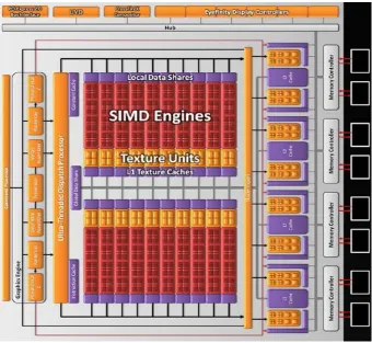
Figure 8 : AMD HD 5870 GPU Architecture
This diagram (Bit-tech.net, 2009) highlights the various components present in a GPU (AMD HD 5000 Series). In the context of GPGPU the relevant components are SIMD Engines (Red), Local Data Shares (Purple, Above SIMD Engines), Texture Units (Orange), Instruction (Purple, Bottom Left) and Constant Caches (Purple, Top Left).
GPUs utilise a SIMD approach to parallel processing; this processing model requires a large quantity
of processing cores compared to a CPU. Fitting the required quantity of processing cores onto a die
necessitates that they are far less complex than their CPU counterparts, lacking features such as
branch predictors. The nature of graphics processing requires that each of the processing cores are
specialised floating point processors. The processing cores are grouped into SIMD Engines, with each
engine containing a small amount of cache memory11 (Fried, 2010, p.5). This cache memory can be
used by all processors in a SIMD engine to share data between themselves. Each SIMD engine is
totally independent and cannot communicate or synchronise with other SIMD engines (Bleiweiss,
2008, p.4) unlike a multi-core CPU. The total number of cores is more difficult to calculate [Equation
1, Equation 2] compared to a CPU because each GPU may have multiple SIMD engines, each of
which contain a number of scalar or vector processors. AMD utilises vector processors in its GPU
architecture whereas Nvidia [Figure 9] GPUs feature a scalar architecture.
11
40
Equation 1 : AMD HD 5770 Processing Cores
The number of processing cores available in a particular model of AMD’s 5000 Series is calculated with the above formula. represents the number of SIMD Engines, the number of processors per SIMD Engine and each processor is a vector unit capable of simultaneously processing instructions.
Equation 2 : nVidia GTX 580 Processing Cores
[image:41.595.74.525.341.708.2]The number of processing cores available in Nvidia’s GTX 500 Series is calculated differently because it is a scalar rather than vector processor architecture. represents the number of SIMD Engines12, each containing processors. The SIMD Engines are however grouped into Graphics Processing Clusters ( )
Figure 9 : Nvidia GeForce GTX 580 GPU Architecture
12 Nvidia calls SIMD Engines CUDA cores to highlight that they can be used for GPGPU applications which use
41
This diagram (Bit-tech.net, 2010) highlights the architectural design of the Nvidia GTX 580. The main difference between this design and that utilised by AMD [Figure 11] is that the SIMD engines (Green) are grouped into Graphics Processing Clusters (GPC).
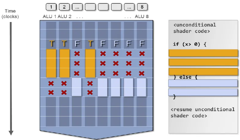
Branching operations pose a particular problem for the SIMD architecture of a GPU, when a branch
operation is encountered it is capable of processing only a single branch at a time [Figure 10]. This
[image:42.595.104.497.240.469.2]impairs performance because all the cores that require the alternative branch are stalled.
Figure 10 : GPU Branch Operation
This diagram (Pfister, n.d., p.26) demonstrates how conditional logic operations on a GPU can greatly impair performance by stalling a number of processing cores (ALU). X represents when the ALU is stalled and therefore idle. Yellow and Blue boxes represent when each ALU is actively processing instructions related to a particular branch of the logic operation.
2.2.4. Parallel Algorithm Design
Algorithms which are capable of utilising parallel processor architectures require a different design
methodology to those developed for a serial implementation. Four discrete stages have been
identified for designing parallel algorithms (Roosta, 1999, p.223):
42 The partitioning stage is used to determine whether Functional or Domain decomposition is the
most suitable method for deriving parallelism from a particular problem. Functional decomposition
involves breaking the algorithm down into its constituent tasks and subsequently identifying which
of these tasks can be executed simultaneously. Domain decomposition attempts to isolate where in
the algorithm multiple items of data have the same calculation applied and can therefore be
executed in parallel.
The communication stage is used to ascertain the amount and type of communications that will be
required between individual threads. Algorithms which require a large amount of inter-thread
communication tend to exhibit reduced performance, especially when “Blocking” type
communication is required.
Agglomeration is the process whereby the design produced using the previous two steps is
evaluated and processing is amalgamated wherever possible. This can improve performance by
reducing the number of potential bottlenecks and amount of inter-thread communication necessary.
It is also used to minimise code complexity and thereby development costs.
The final stage in the design process is mapping. This is where the most applicable parallel
processing architecture is selected for the particular problem being computed. When the
architecture has been chosen, the concurrent tasks are “mapped” to the specific hardware being
employed so that the work load is balanced for all processing cores thereby maintaining optimal
resource utilisation and performance.
Ian Foster (1995, pp.27-28,42,49-50,56-57) has produced a checklist for the design process described
above. The basic criteria for each stage are listed below:
1. Partitioning
a. Is the partitioning at least an order of magnitude more than number of cores?
b. Are there significant amounts of redundant computation and memory usage?
c. Are tasks of comparable size?
d. Does the task scale with problem size?
2. Communication
a. Do the tasks require similar amounts of communication?
b. Do the tasks communicate with a small number of neighbours?
c. Is the communication non-blocking?
3. Agglomeration
43 b. Does replicating computing impact performance?
c. Does replicating data affect scalability?
d. Does agglomeration leave tasks with similar computation time requirements?
e. Do tasks scale with problem size?
f. Has agglomeration removed too much concurrency?
g. Could the number of tasks be reduced wi