2016 International Conference on Wireless Communication and Network Engineering (WCNE 2016) ISBN: 978-1-60595-403-5
A Substituted Method for TRP Measurement
Feng-feng WANG
1, Shuang-wen ZHANG
2and Smart LI
21
Global Access Building, No.138 Binfang Avenue, Meizhou, Guangdong, China 2
Electronic Testing Building, Shahe Road, Xili, Nanshan District, Shenzhen, China
Keywords: OTA, TRP, Bluetooth, Wi-Fi.
Abstract. OTA (Over-the-Air) measurement was carried out on a smart phone for several typical
configuration, a substituted method was developed to execute the TRP (Total Radiated Power) test, the TRP results of Bluetooth and Wi-Fi were analyzed that could proven the validation of the new method.
Introduction
M2M has grown up to be the most popular industry during the past decade, while mobile internet was playing the most important role during the whole process. More and more kinds of smart wireless devices appeared in the markets, including wireless switch, flying camera, smart cup, etc. These product was making it more and more convenient for people’s life. Meanwhile, more and more kinds of wireless communication technologies were employed to meet the various requirements, such as Bluetooth, Wi-Fi, Zigbee, Z-wave[1~4], etc. Most of these wireless devices worked at the 2.4GHz ISM band, and more others frequency bands may be used in the future. Many researchers were concentrating on improving the performance and reliability of the communication, such as MIMO (Multiple Input and Multiple Output) [5,6] antennas, Beamforming [6,7] antenna, etc.
On the other hand, the OTA (Over-the-Air) measurement was an important method to verify the communication performance of the wireless devices [8~10]. There’re two means of OTA measurement, named passive test and active test, they can both check the performance of the design. Passive test [8] can tell us the parameters of the antenna, such as Pattern, Gain, Efficiency, etc, while active test involves the RF performance of the wireless devices, including TRP (Total Radiated Power) and TIS (Total Isotropic Sensitivity) [9]. Active test always means more costs, it needs more test instruments and longer test time, especially for those wireless devices worked at ISM band, people have to choose the passive test.
In this paper, a substituted method was developed to execute the TRP test, the test configuration was also discussed. The TRP results of Bluetooth and Wi-Fi were analyzed.
TRP Measurement
Generally, OTA measurement should be performed in a FAC (full-anechoic-chamber) [11]. There are two acceptable measurement methods, named the “conical” cut method and the “great circle” cut method. In both Conical Cut and Great Circle Cut methods, spherical coordinate system is employed to position the EUT (equipment under test).
For a complete sphere measured with N Theta intervals and M Phi intervals, both with even angular
spacing, the Total Radiated Power is calculated as follows[9].
1 1 1 0 sin , , 2 N i M j i j i j i EiRP EiRP NMTRP
(1)
where EiRP means Effective Isotropic Radiated Power. The TRP results can indicate the RF
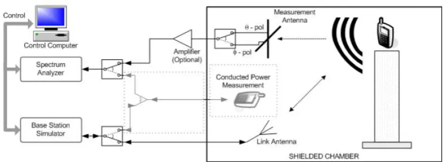
Typical TRP Test Configuration
Figure 1. A typical TRP test configuration.
In the test setup described above, a base station simulator is required, such as CMW500, CBT, etc. However, some wireless communication technology may not be supported by the instrument supplier in time, testing facility and manufactures could not obtain the proper base station simulator. Nowadays there’re still no base station simulator with complete function for Zigbee and Z-wave, it’s difficult to verify the TRP or TIS for those devices, the passive test is the unique choice.
Substituted TRP Test Configuration
For those wireless devices without signal supporting by base station simulator, obviously, the active test cannot be performed by the typical method. Although the passive test results can tell us the pattern of the antenna itself, it cannot indicate the performance of the whole device, the enclosure and connector may significantly influence on its RF performance.
In this paper, a substituted method was employed to do TRP test for the devices working in test mode. In test mode, the RF parameters of the device can be defined as desired, such as RF output power level, duty cycle, working frequency band, etc. During the test, the device was working in test mode, it kept transmitting from the antenna with a typical duty cycle, so base station simulator is not required, there’s no air link.
Figure 2. TRP test configuration of substituted method.
In this measurement method, EiRP at each point was measured as the same as that done in
[image:2.595.77.517.517.693.2]Test Results Analysis
In this section, active OTA tests were carried out on a smart phone at bluetooth and Wi-Fi configuration, test results of both the traditional method and the substituted method were also listed in the following tables and figures.
The middle channel of Bluetooth 3.0 and the middle channel of 802.11 b were tested by these two method, the results show the difference of these two method. The minimum frequency step was 0.05MHz in the substituted method, and 15-degree intervals were used for both of the method.
[image:3.595.64.517.270.548.2]During the test, the smart phone under test was working in test mode. For Bluetooth 3.0, the phone was working at 3-DH5 mode, the test were executed on the test system TS8991 (manufactured by Rohde & Schwarz). While for 802.11b mode, the transmitting power was set at 19 dBm with 11Mb/s transmitting speed, the test were executed on the test system AMS8600 (manufactured by ETS-LINDGREN).
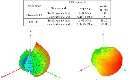
Table 1. Table headings.
Work mode
TRP test results
Test method Frequency results (dBm)
Bluetooth 3.0 Traditional method 2441 MHz 4.60 Substituted method 2441.10 MHz 7.27
802.11 b Traditional method 2442 MHz 18.20 Substituted method 2442.05 MHz 20.34
[image:3.595.65.529.301.754.2]
a. traditional method b. substituted method
Figure 3. 3D graph of Bluetooth 3.0.
Total P o w e r ( d B m ) -25 30 -15 -5 5 15 X Y Z Azimuth = 0.0 Elevation = 0.0 Roll = 0.0
a. traditional method
Total P o w e r ( d B m ) 5 30 10 15 20 25 X Y Z Azimuth = 0.0 Elevation = 0.0 Roll = 0.0
b. substituted method
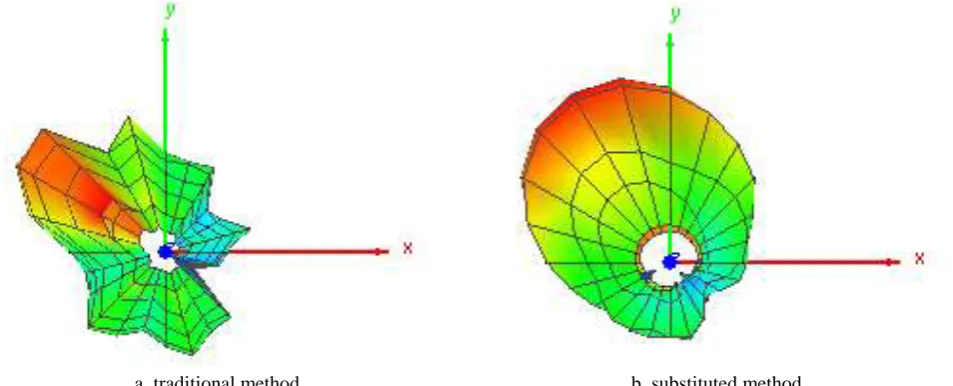
The results showed the substituted method may achieve a higher results, the following 2D graph could help explain it. Since the devices working in test mode kept transmitting at a desired power level, the distribution of the RF power radiating may be more closer to the pattern of the antenna. While in traditional method, there’s an air link between the devices and base station simulator, the signal generated by the transmitter may not be captured adequately, especially for those captured by the base station simulator.
[image:4.595.64.541.156.349.2]
a. traditional method b. substituted method
Figure 5. 2D graph of Bluetooth 3.0.
The traditional method can simulate the conventional behavior of the wireless device, while test mode may mean a perfect transmitting status, the results will be more closer to the maximum value. The substituted method could easily apply to the Zigbee and Z-wave devices, also to the equipments operating on others frequency band, such as RFID in UHF band, as long as the test system was able to cover those bands, which could meet the requirement of quite zone, ripple and pass loss.
Summary
In this paper, a substituted method was developed to execute the TRP test for those wireless devices without signal supporting by base station simulator, the test configuration was also discussed. The TRP results of Bluetooth and Wi-Fi obtained by both methods were analyzed, the substituted method may achieve a result close to the maximum value. For those wireless devices without signal supporting by base station simulator, the substituted method is a good schedule for the TRP test.
Acknowledgement
This research was financially supported by China Mobile Group Guangdong Co., Ltd. Meizhou Branch, and CCIC-Southern Electronic Product Testing (Shenzhen) Co., Ltd. offered the free test service.
References
[1] Information on http://www.bluetooth.com
[2] Information on http://www.wi-fi.org
[3] Information on http://www.zigbee.org
[4] Information on http://www.z-wave.com
[6] Information on http://www.3gpp.org
[7] J. Lita, T. K.-Y. Lo. Digital beamforming in wireless communi-cations. Boston: Artech House Publishers, 1996.
[8] IEEE Standard Test Procedures for Antennas, ANSI/IEEE Std 149-2003
[9] Test Plan for Wireless Device Over-the-Air Performance - Method of Measurement for Radiated RF Power and Receiver Performance, CTIA Certification Test Plan, Ver. 3.6, Washington, DC, June, 2016.
[10] Test Plan for RF Performance Evaluation of Wi-Fi Mobile Converged Devices, CTIA and Wi-Fi Alliance Certification Test Plan, Ver. 2.0.2, Washington, DC, October, 2015.