2016 International Congress on Computation Algorithms in Engineering (ICCAE 2016) ISBN: 978-1-60595-386-1
1 INTRODUCTION
The crankshaft as the most important moving part of a piston compressor plays a very important role in the compressor. There are many reasons affect the overall performance of the crankshaft because its complex geometry and serious stress concentration phenome-non. Failure examples show that the main failure form is fatigue failure which caused by the alternate load though connecting rod plays on the crankpin. The alternating load includes gas power, friction, recipro-cally rotating inertia force and input torque. According to the literature, crankshaft breakages mainly appear at the transition arc of main shaft and crankpin (Silva F S.2003). Therefore, how to reduce the maximum stress concentration becomes an indispensable content in design of the crankshaft. With the development of finite element method (FEM) and computer technolo-gy, stress and deformation changes with structural parameters of crankshaft can be more clearly de-scribed by FEM software, which becomes a popular
means in improving the level of crankshaft design. Lots of studies have been made to analyze the stress and deformation of the crankshaft in compressors and engines. Li, H. Z. et al. (1991) presented the optimum design of crankshaft fillets by means of finite element and mathematical programming methods for 6120Q gasoline engine. The maximum stress at the recom-mended crankshaft fillet reduced considerably. Cor-don (1997) analyzed the stress of crankshaft fillets by three-dimensional finite element method, and op-timization values of the fillet radius were obtained. Hu, Y.P. (2006) developed an improved crankshaft simu-lation model of 6160 diesel engine to predict crack position and fatigue life.
Research on the static strength and fatigue strength analysis is the main content of crankshaft design. The static strength analysis is conducted to obtain the stress distribution under the maximum load permitted and identify the dangerous section. Su, T. X. et al. (1995) have done a numerical simula-tion focusing on the bending stress of crankshaft asso-ciated with the oil holes location and transition radius. The research found that stress at the crankpin
jour-Optimum Design on Structural Parameters of Reciprocating
Refrigeration Compressor Crankshaft
Guangyu Mu1,2*, Feng Wang3 & Xiaozhen Mi3 1
Mechanical and Power Engineering College, Dalian Ocean University, Dalian, Liaoning, China
2
Mechanical Engineering College, Dalian Jiaotong University, Dalian, Liaoning, China
3
Institute of Modern Rail Transportation, Dalian Jiaotong University, Dalian, Liaoning, China
ABSTRACT: Crankshaft is one of the main components of a piston refrigeration compressor. Its structure pa-rameters influence the reliability and service life. [Research objective] Improve the reliability of the crankshaft and further understand the impact of structural parameters on the strength of the crankshaft. [Research method] The forces acting on crankshaft are analyzed on the basis of dynamic calculation of reciprocating compressor working process. Finite Element Method (FEM) is applied for three-dimensional modeling and static strength analysis. [Research result] The stress at the transition fillet of crankshaft journal under the maximum comprehen-sive piston force is obtained accordingly. The reliability and accuracy of this model is verified by the experi-mental results. The influence of the crankshaft with crankpin diameter, center distance of adjacent crankpins and fillet radius on stress concentration has been investigated in detail. The optimal undercut fillet is designed for reducing the maximum stress obviously. The results provide a reference for similar design and production of compressor crankshaft.
Keywords: crankshaft; crankpin; Finite Element Method (FEM); stress analysis; optimal design
nal fillet could be lightened by increasing oil holes diameter or lowered oil holes position appropriately. Wang, D.H. (1997) comparatively analyzed the static strength with four kinds of FEM model and boundary condition of crankshaft. He proposed that the bending moment and torsion moment in crankshaft journal have great influence on the calculation results. Y.KANG et al. (1998) established the finite element model of crankshaft both in entity and beam elements. By comparison with the experimental data, entity elements model is the better one. Feng, G.S. et al. (2003) investigated the distortion and stress of 4190 diesel engine’s crankshaft. Compared with the whole crankshaft model, the reliability of single crank stress analysis method was undesirable due to its simplified boundary conditions. Choi K.S. (2009) analyzed static strength, fatigue strength and vibration characteristics of the crankshaft combined with the finite element method and modal. The result verified the accuracy of numerical analysis calculations precisely.
Many scholars have studied the fatigue strength and fatigue life of crankshaft as accurately as possible. D. Taylor, W (1999) presented an approach based on equivalent stress intensity for analyzing the stat-ic stress and fatigue strength. Lee Y.L (2001) calcu-lated the fatigue strength and safety coefficient of the crankshaft. Both the simulation results and experi-mental results are consistent. Zhang, G. Q et al. (2006) have done parametric studies on fatigue life of crank-shaft using nominal stress method and local stress method respectively. The results indicated that the traditional design is too conservative and not accurate enough. Yang Z (2014) analyzed the dynamic charac-teristics and load spectrums of the crankshaft com-bined with the finite element method and multi-body dynamics technique. The fatigue life and failure dan-ger section of the crankshaft were obtained. All of these works lay a foundation for the research of the crankshaft strength deeply.
In this paper, the influence of crankpin diameter, center distance of adjacent crankpins and crankshaft journal fillet radius on stress concentration has been studied based on Finite Element Method (FEM). The undercut fillet is designed for optimizing the life and reliability of crankshaft. It provides a theoretical basis for the optimum design of compressor crankshaft.
2 STRENGTH ANALYSIS OF THE CRANKSHAFT
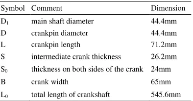
A crankshaft used in a medium-sized semi-hermetic piston compressor is adopted for the research. The reciprocating mass of the compressor is 0.4756kg; the compressor rated speed is 1,450r/min and the rated power is 2.2kW. The main dimensions of the crank-shaft are shown in Table1.
The crankshaft material is 40Cr steel. The main physical constants of 40Cr steel are shown in
[image:2.516.266.463.88.191.2]Table 2.
Table 1. Main dimensions of the crankshaft.
Symbol Comment Dimension
D1 main shaft diameter 44.4mm
D crankpin diameter 44.4mm
L crankpin length 71.2mm
S intermediate crank thickness 26.2mm
S0 thickness on both sides of the crank 24mm
B crank width 65mm
[image:2.516.268.460.215.246.2]L0 total length of crankshaft 545.6mm
Table 2. The physical characteristics constants of 40Cr steel.
Material Elastic modulus
E/Gpa
Poisson's ratio
µ
Density
ρ/g·cm-3
40Cr steel 198 0.29 7.82
2.1 Three-dimensional modeling and meshing
Three-dimensional modeling is precisely constructed for calculating the strength of whole crankshaft based on Pro/Engineer software. Taking into account the meshing grid at the junction of oil channels and, shaft necks are prone to adverse elements, the oil passages are ignored in the model (Okamura H, 1995).
Since hexahedral meshing has more advantages in calculation precision, deformation characteristics and anti-distortion degree than tetrahedral meshing, the finite element model of crankshaft is hexahedral meshed in HyperMesh software with a total of 219,095 nodes and 612,220 elements.
2.2 Force boundary conditions and constraints
The force boundary conditions of finite ele-ment model include loads, bearing radial constraints and input torque, etc (Tadashi N, 2002). The force acting on piston pin mainly contains air force
Fg, reciprocating inertia force Fj and friction force Ff .
Since the forces’ directions are all along the central line of the cylinder, the equations of comprehen-sive piston force Fpcan be written as follows:
p g j f
[image:2.516.267.430.523.617.2]F = F + F +F
(1)Figure 1. Schematic of crank linkage force.
stress analysis under the condition of the largest com-prehensive force, which provides reasonable values to assure the simulated results are physically meaningful. Figure 1 presents that the total force Fa imposed on piston are decomposed into connecting rod force Fl and lateral force perpendicular to the cylinder wall Fh. The Fl as well as Fh can be expressed by the ratio of crank radius and connecting rod length λand crank angle a as follows:
l α 2 2
1 F = F
1 -λsinα
⋅ (2)
h α 2 2
λsinα
F = F
1 -λsinα
⋅ (3)
The force Fl acting on crankpin center through the connecting rod are decomposed into the circumferen-tial tangencircumferen-tial force Ft and radial normal force Fr. These two forces can be calculated as:
t α 2 2
λsin2α
F = F sinα+
2 1 -λsinα
(4)
2
r α 2 2
λsinα
F = F cosα
-1 -λsin α
(5)
The simplified forces model of crankshaft is shown in Figure 2. The tangential force Ft and normal force Fr were applied on the center node of crankpin.
The constraints of crankshaft are specified as fol-lows:
Radial constraints are applied in the position of crankshaft neck for sustaining two bearings respec-tively and circumferential rotation.
Displacement constraints are arranged to the short end of main shaft for limiting the axial movement.
The power input end of crankshaft needs to make steel processing for reducing stress concentration on the center node.
[image:3.516.54.463.214.270.2]According to the formula T=F × D1, input torque T can be described as the tangential force F exerting on the circumference face of power input, the moment arm is D1/2. The loads on crankshaft are shown in Table 3.
2.3 Result analysis
[image:3.516.57.241.511.574.2]After arranged the load boundary conditions and con-straints, the static stress distribution of crankshaft is calculated in ANSYS under the condition of maxi-mum piston comprehensive force. It was found that the maximum stress was 83Mpa at the journal fillet of second crankpin, which is located in the vicinity of 300 degrees counter-clockwise viewing from motor. According to the experimental results, the destruction of crankshaft commonly occurs at transition fillet of crankshaft journal, which is consistent with the calcu-lated results. Therefore, the finite element model of static stress analysis is valid correspondingly. Stress distribution of the crankshaft is shown in Figure 3:
Figure 3. Stress distribution of crankshaft. Figure 2. Simplified forces model of crankshaft.
Table 3. Loads on crankshaft.
Crankshaft position feature
The first crankpin The second crankpin
Input torque
T (Nm)
Input Force
F (N)
Normal force F'r (N)
Tangential force F't (N)
Normal force Fr (N)
Tangential force
Ft (N)
The largest comprehensive
[image:3.516.264.464.569.635.2]3 PARAMETERS OPTIMIZATION OF THE CRANKSHAFT
The structural parameters of crankshaft impact on the strength are studied by modifying the geometric di-mensions of the finite element model. Optimization of the crankshaft structural parameters needs to integrate the consideration of crankshaft strength, stiffness, weight and reliability. Since the maximum stress emerged when comprehensive piston force is the larg-est, the static strength analysis is carried out under this condition. In this section, we emphasize our analysis in structure parameters as crankpin diameter, center distance of adjacent crankpins and common fillet ra-dius inflecting on the maximum stress of crankshaft.
3.1 Crankpin diameter
The changes of maximum stress with the crankpin diameter increased have been studied based on the main shaft length and thickness of crank arm invari-antly. Figure 4 presents the maximum stress at the journal fillet, which is reduced with the increase of crankpin diameter. Crankpin diameter is also affected by bearing diameter and quality, the overall stiffness and weight of the crankshaft subsequently. The crank-pin diameter could be improved only in permit condi-tions.
Figure 4. Maximum stress changed with crankpin diameter increase.
3.2 Center distance of adjacent crankpins
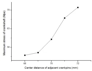
The changes of maximum stress with the increasing center distance of adjacent crankpins have been also studied based on main shaft length, crank thickness and crankpin diameter invariantly. Figure 6 presents the maximum stress at the journal fillet, which is gen-erally increased with the center distance growth. However, reducing the center distance of adjacent crankpins will shorten the stroke of connecting rod and resulted in lower volumetric efficiency of the compressor. Therefore, the structural parameters of stroke / bore size ratio should be reasonable chosen for the relative clearance volume from 1.5% to 6% in design of the small–and-medium-sized compressor.
Figure 5. Maximum stress changed with the center distance of adjacent crankpins increase.
Figure 6 shows that the maximum stress is 53MPa or 58MPa when center distance of adjacent crankpins is 68mm or 70mm.
(a) Center distance = 68mm
(b) Center distance = 70mm
Figure 6(a-b). Stress distributions when center distance of adjacent crankpins is 68mm or 70mm.
3.3 Common fillet radius
[image:4.516.285.440.55.176.2] [image:4.516.272.453.250.463.2] [image:4.516.75.230.357.471.2] [image:4.516.269.440.506.638.2]The size, shape and surface quality of the crankpin journal fillet have significantly affected on stress con-centration and fatigue strength. The maximum stress can be gradually reduced with the appropriate increase of common radius R, as shown in Figure 7. When R increased over 3mm, the effect of stress reduction is not obvious, and length of effective pressure will be shortened correspondingly and unfavorable for the crankpin working. Therefore, the crankshaft fillet radius should not be too large.
3.4 Undercut fillet
[image:5.516.275.452.184.597.2]In order to solve the above problem, the undercut fillet was designed for reducing the maximum stress. And the structure of undercut fillet is shown in Figure 8:
Figure 8. Undercut fillet of crankshaft.
The undercut fillet is arranged within the fillet of crank pin and crank, which is recommended when the axial length of the compressor is strictly limited such as angle-type compressors. Meanwhile, the undercut fillet should be avoided cutting too deep otherwise it will weaken the strength of the crank.
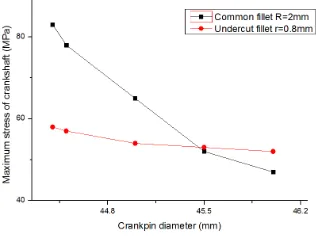
Figure 9. Comparison of the maximum stress between un-dercut fillet and common fillet.
Figure 9 shows the comparison of maximum stress between common fillet and undercut fillet. The black line represents the maximum stress varying with the increase of crankpin diameter when common fillet R is 2mm. It was found that the maximum stress is very strong when crank pin diameter is small and then de-clined rapidly with the diameter increase. There is a
large variation range of the maximum stress. The red line represents the maximum stress changed with the increase of crank pin diameter when undercut fillet r is 0.8mm. However, the maximum stress at the journal of undercut fillet decreased generally and continued its downward trend when the diameter is less than 45.5mm. The maximum stress of undercut fillet ex-ceeds that of common fillet when diameter is larger than 45.5mm. Therefore, undercut fillet could be se-lected for reducing the stress concentration according to the diameter of crank-pin under the premise of en-suring the overall strength of crankshaft.
(a) D = 44.4mm
(b) D = 44.5mm
(c) D = 45mm
(d) D = 46mm
Figure 10(a-d). Stress distribution on crankshaft with the increasing of crankpin diameter (D) when undercut fillet r=0.8mm.
[image:5.516.98.209.229.325.2] [image:5.516.73.232.430.548.2]when undercut fillet (r) is 0.8mm. The maximum stress occurs in the undercut fillet of crankshaft jour-nal, which is generally lower than common fillet. The maximum stress is 58MPa, 57MPa, 54MPa or 53MPa when crankpin diameter (D) is 44.4mm, 44.5mm, 45mm or 46m
4 CONCLUSIONS
In this study, static stress analysis is conducted for a whole crankshaft of reciprocating refrigeration com-pressor. The weak position of strength was found in crankshaft journal fillet, where reached 83Mpa at the maximum comprehensive piston force. The influences of crankpin diameter, center distance of adjacent crankpins and journal fillet radius on the maximum stress of crankshaft have been investigated. The main conclusions are listed as follows:
The increase of crankpin diameter causes a signifi-cant decrease in fillet stress when the thickness of the crank arm is unchanged.
With the center distance of adjacent crankpins shortened, the fillet stress decreases slowly.
The maximum stress can be decreased with the crankpin fillet radius R increase. When R increased over 3mm, the effect of stress reduction is not obvious, and the journal pressure area is reduced, which is un-favorable for the crankpin working. Therefore, the crankshaft fillet radius should not be too large.
To decrease the maximum stress of crankshaft, the undercut fillet structure of the crankpin was designed. The static stress analysis of common fillet and under-cut fillet are compared and found that the maximum stress at the crankshaft journal was significantly de-creased when crankpin diameter is 44.4mm. Once the diameter exceeds 45.5mm, the stress in common fillet is smaller than that of undercut fillet. Therefore, less stress can be obtained in the range of 44.4mm– 45.5mm of the crankpin diameter. Furthermore, more accurate stress analysis data of crankpin fillets was obtained in this study, which provides a theoretical basis for the improvement of small-and-medium-sized compressor crankshaft.
ACKNOWLEDGEMENT
This paper was sponsored by Liaoning Provincial Department of Education of China (GN: L2013280).
REFERENCES
[1] Cordon R Pennock. 1997. Force analysis of the apex
seals in the Wankel rotary compressor including the in-fluence of fluctuations in the crankshaft speed. Mech. Mach. Theory, 32 (3):349-355.
[2] Choi K.S. & Pan J. 2009. Simulations of stress distribu-
tion in crankshaft section under fillet rolling and bending
fatigue test. International Journal of Fatigue, 31:
544-557.
[3] D. Taylor, W. Zhoub, A. J. Ciepalowicz. & J. Devlukia,
1999. Mixed-mode fatigue from stress concentrations: an approach based on equivalent stress intensity, Interna-tional Journal of Fatigue.
[4] Deng Banglin, Yang Jing & Fu Jianqin, 2011. The
Fric-tion Analysis of Main Bearing on An Internal Combus-tion Engine Based on Multi-body Dynamics and Elasto --Hydrodynamic. Electric Information and Control En-gineering (ICEICE), Wuhan, China.
[5] Feng, G. S., Zhang, Y. T. & Zhang, Y. S. 2003. Three-Dimensional FEM Analysis of Engine Crankshaft
Static and Dynamic Behaviour. Chinese Internal
Com-bustion Engine Engineering, 24(2): 74-77.
[6] Hu, Y.P., Mao, H.Y. & Hu, Y.P. 2006. A
3Dimension-Finite Element Analysis on the crankshaft of 6160 diesel engine. Journal of Shandong University (Engineering science), 4(2): 99-103.
[7] Klemenz M. & Schulze V, 2010. Application of the concept of local fatigue strength after shot peening of notched components based on numerical simulations. Materials Science Forum, 638: 912-917.
[8] Lee Y.L. & Morrissey W., 2001. Uncertainties of
ex-perimental crankshaft fatigue strength assessment.
In-ternational Journal of Materials and Product Technolo-gy, 16: 379 - 392.
[9] Li, H. Z., Yang, S.L. & Yang, Z.C. 1991.Optimum De-sign of Crankshaft Fillets. Chinese Internal Combustion Engine Engineering, 12: 72-76.
[10] Okamura H. & Shinno A. 1995. Simple Modeling and Analysis for Crankshaft Three-dimensional Vibrations, Part 1: Background and Application to Free Vibrations. ASME Journal of Vibration and Acoustics, 117(1): 70-79.
[11] Silva F S. 2003. Analysis of a vehicle crankshaft failure,
Engineering Failure Analysis. 10: 605-616.
[12] Su, T. X., Zhang, R.H., Cai, P. 1995. A research on
var-ied rules of crankshaft bending stress using FEM. Jour-nal of Vehicle Engine, 4: 35-40.
[13] Tadashi N, Tatsuya I. & Shingo U. 2002. Development of simulation technology for dynamic behavior of
crankshaft systems in motorcycle engines. JSAE Review,
23: 127-131.
[14] Wang, D.H., Yin, J.M. & Yuan, Y.N. 1997.
Three-dimensional Finite Element Method in research on crankshaft strength of multi-cylinder engine. Journal of Jiangsu University of Science and Technology, 18(1): 7-11.
[15] Xie Jizhou., 1992. Handbook of Low-cycle Fatigue.
Bei-jing: Beijing Institute of Materials Publications.
[16] Xu Jinyuan, Li Zhen & He Zhixian, 2013. Dynamic
op-timization for the main drive system of a reciprocating compressor considering joint friction (ICMEE. Mechan-ical & Electronic). Tianjin: Tianjin Press, pp: 315-316.
[17] Yang, Z. 2014. Application of the Finite Piece Method to
Simulate Viscoelastic Fluid Flows in L-shaped Channel. Applied Mechanics and Materials, 38: 100-103.
[18] Y. Kang, G. J. Sheng & M.H. Tseng. 1998. Modal
anal-yses and experiments for engine crankshafts. Journal of Sound and Vibration.
[19] Zhang, G. Q., Huang, B.C. & Pu, G. Q. 2006.Crankshaft
Fatigue Life Calculation Based on Dynamic Simulation
and FEA. Chinese Internal Combustion Engine