2017 3rd International Conference on Electronic Information Technology and Intellectualization (ICEITI 2017) ISBN: 978-1-60595-512-4
Electric Wheel Automobile Electro-hydraulic
Composite ABS Layer Control Based on
Constant Hydraulic
Houzhong Zhang, Xinfei Wang, Jinlin Ma and Qi Wu
ABSTRACT
In view of the big hydraulic pressure fluctuation, high adjustment frequency, great control error of sliding rate in the process of braking of distributed driven electric vehicle (electric wheel motors). The hierarchical control strategy based on the constant hydraulic pressure is proposed. The upper part of this strategy calculates the braking torque of each wheel for the control of wheel slip rate by using pavement recognition technology, the vehicle dynamics model based on Carsim software and the vehicle state parameters. The lower part assigns the torque to hydraulic braking and electrical braking wheel to implement the anti-lock function based on constant hydraulic pressure, the motor braking adjusts the slip rate preferentially to reduce the frequency and amplitude of hydraulic pressure fluctuations, improving the stability of braking, The hierarchical control strategy simulation experiments are implemented respectively on splitter road through Carsim and Matlab/Simulink co-simulation experiment to verify the effectiveness of the proposed strategy. Simulation results show that compared with the traditional logic threshold ABS control strategy, the electro-hydraulic compound ABS hierarchical control strategy is able to keep hydraulic pressure constant and improve the stability and comfort effectively in the braking process.
________________________
INTRODUCTION
How to coordinate the motor braking and the hydraulic braking is the core part of the electric-liquid composite brake when the wheels are in the ABS control. In term of the coordination control of electro-hydraulic compound braking, some research proposed that with drawing the motor braking gradually on entering the ABS to ensure the safety of braking, but this method can not timely compensate the loss of motor braking force because of the hydraulic with hysteresis and the braking force is insufficient, In order to solve this problem, Li he [1] designs the hydraulic hysteresis compensation strategy, through the setting of threshold, realizes the motor brake feedback in advance, make the hydraulic braking system action in advance, solve the problem of the hydraulic brake lag to a certain extent. Yimin Gao [2] put forward the integrated motor regenerative braking and traditional electronic control of the ABS braking system, with designing the motor braking torque threshold accurately, making the regenerative braking work compatible with ABS, they designed the distinction of logic braking force between conventional brake and emergency brake. Bin Cheng[3] designed the algorithm to adjust hydraulic braking to control the slip rate when the actual slip rate was achieved to the desired slip rate, adjusting the hydraulic braking control slip rate when detecting the tendency of the wheel lock. Another kind of coordination control are research on coordination with motor brake and hydraulic braking in ABS. Dong Peng[4] used the control theory of fuzzy control fuzzy control strategy based on the motor brake and hydraulic brake participating anti-lock brake at the same time, they designed the optimal slip ratio of fuzzy control strategy and braking force dynamic allocation strategy, realizing the wheel slip rate steady at the optimal slip ratio through the motor brake and hydraulic brake dynamic allocation. Qingzhang Chen [5] proposed that motor brake and the traditional ABS adopt logic threshold method at the same time, realizing the coordination control of motor brake system and hydraulic brake system by keeping the proportion of motor braking and improving the energy recovery rate. Guozhu Zhao[6] proposed the regenerative ABS system through control of motor braking and reverse braking to prevent the anti-lock of wheel in term of condition of the pure motor braking on the low adhesion coefficient road. The control theory of variable structure, fuzzy control theory and dual closed-loop control strategy are adopted to control the regenerative ABS. The research of electro-hydraulic composite brake control strategies above mainly focus on optimizing energy recovery efficiency under the condition of braking efficiency and safety. Less attention is paid to the study of hydraulic stability and comfort in the anti-lock braking.
on the principle of constant hydraulic pressure. It tries to reduce the fluctuation of hydraulic braking and in order to improve the stability and comfort of the emergency braking. The motor brake is adjusted by PID controller, which can make full use of the motor brake rapid response, precise control and realize the real-time control of slip rate.
ELECTRIC WHEEL BRAKING SYSTEM AND MODEL
Structural of Braking System
In this paper, the structure of distributed driven electric vehicle braking system is shown in Fig. 1, four wheels were installed hub motor respectively, vehicle controller (vehicle control unit, VCU) gain pedal position, the wheel slip ratio and the current state of the battery pack information in the process of braking. VCU calculates the braking torque required, and then assign the braking torque to hydraulic braking and electrical braking, order are sent via CAN bus to ABS controller and motor controller (motor control unit, MCU). ABS controller calculates the target brake pressure according to the instructions of hydraulic braking force. It takes four wheel cylinder pressure of the hydraulic pressure and wheel slip rate and putting them back to the ABS controller. MCU control motor torque based on the electric braking command, the sum of electric braking force and hydraulic braking force meet the required braking requirements.
Hydraulic Brake Inverse Model
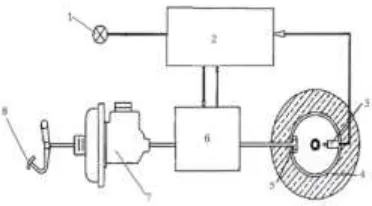
ABS system mainly includes wheel speed sensor; brake hydraulic regulator; master cylinder and wheel cylinder, as shown in Fig. 2. When braking, the hydraulic braking is used to provide the basic braking force. The force analysis of the vehicle in the braking process is shown in figure 3, and the influence of the rotation inertia of the vehicle parts is ignored. The motor equation is expressed as follows:
wheel cylinder valve
ABS Controller Motor
Motor Motor
Motor
VCU Controller MCU
Controller
ABS hydraulic control unit
battery pack voltage
circuit hydraulic
circuit
can area network signal line
wheel speed sensor brake
1. Alarm device 2. Electronic control devices 3. Wheel speed sensor 4.Wheels 5. Brake cylinder 6. Brake pressure regulating device 7. Master cylinder 8. Brake pedal
Figure 2. Schematic diagram of ABS hydraulic system.
ma
F
t
F
x
F
V
(1)In equation (1), Ft is the driving force of the vehicle, Fx is the vehicle braking
force,
F
V is the total resistance. The paper only considers air resistance and rolling resistance, i.e.
2
2 1
V A C mgf V
F D a
(2)
In braking, through the equation (1) and (2) the inverse braking model can be achieved:
b a D
K
ma V A C mgf P
2
exp
2
1
(3)
Motor Braking Model
When braking, the motor braking control the adjustment of the slip rate, Fmac is the biggest motor braking force allowed by the vehicle dynamic state, it is affected by motor speed, battery capacity, etc. The specific expression is:
m m m
m m m
m
N n w
T
N n w N
P
F
mac 9550(4)
In the formula: Tm is the motor rated torque, Nm is the motor rated speed, Pm is the motor rated power, nm is motor speed; ∏ w is the influence factor of the motor system. When the ∏ w is larger, the motor braking force that motor provide is larger and the energy recovery efficiency is high. It should be appropriately lowered for taking stability into consideration.
ELECTRO-HYDRAULIC COMPOSITE ABS CONTROL STRATEGY
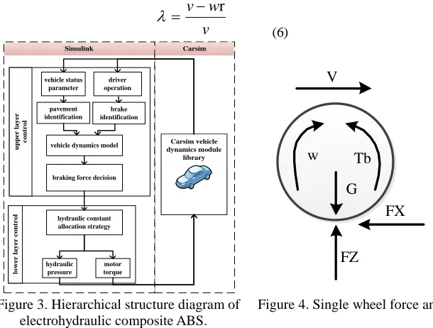
In term of electric-hydraulic composite braking system, regulating motor braking to control the wheel slip ratio firstly. When the biggest motor braking force can not meet the needs of slip rate adjustment or motor fails, hydraulic braking participates. The layered control strategy of electro-hydraulic composite ABS for electric wheels is shown in Fig.3. Hierarchical control strategy is divided into two layers according to the function of design, the upper is total braking torque maker, the lower is the distribution based on the constant hydraulic pressure, which contains a method of motor failure. The hydraulic braking force and motor braking force are implemented to simulate vehicle via Carsim software finally.
Upper Controller
ROAD RECOGNIZER
Under the influence of pavement (cement pavement and asphalt pavement, etc.), the types of attachments (snow and ice, etc.) and tire structure change, the road and tire adhesion exist a corresponding relation, vehicle dynamics response contained the characteristics of road and tire adhesion. In this article, the road identification is based on vehicle dynamic response characteristics.
The road use adhesion and slip rate are defined as[7] :
Z X
F F Pexp
v w v r
(6) Carsim Simulink u p p e r l a y e r c o n tr o l lo w e r l a y e r c o n tr o l Carsim vehicle dynamics module library braking force decision
vehicle status parameter
vehicle dynamics model
[image:6.612.141.446.89.320.2]hydraulic constant allocation strategy hydraulic pressure motor torque pavement identification brake identification driver operation w Tb G V FZ FX
Figure 3. Hierarchical structure diagram of Figure 4. Single wheel force analysis. electrohydraulic composite ABS.
In the process of linear braking, the single-wheel force analysis is shown in Figure 4:
The wheel meets the motion equation[8]:
JwFX TbTf
r
(7)
The equation (6) is substituted into the equation:
Zr f b F T T w J
(8)
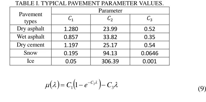
TABLE I. TYPICAL PAVEMENT PARAMETER VALUES.
Pavement types
Parameter
𝐶1 𝐶2 𝐶3
Dry asphalt 1.280 23.99 0.52
Wet asphalt 0.857 33.82 0.35
Dry cement 1.197 25.17 0.54
Snow 0.195 94.13 0.0646
Ice 0.05 306.39 0.001
3 1
2
1 e C
C C
(9)
In the formula: C1, C2 and C3 are the parameter values of typical pavement, is slip rate. The typical road parameter values are shown in table I.
TOTAL BRAKING TORQUE
It can be seen from the model of vehicle dynamics that the maximum ground power Fmax which is the product of μand vertical force FZ. However, this is the lock
braking torque of the wheel, which should be reduced properly. The target system is:
Fbrak FZ -Fmar (10)
In the formula: Fmar is the fluctuation margin, which is the reduced value on the
Fmax basis. Fmar is:
Fmar 500ka (11)
ka is determined by the road adhesion coefficient and the surface roughness, The
torque fluctuation is about 400 Nm on high adhesion road braking based on the traditional logic threshold control strategy. The torque fluctuate is about 100Nm on low attachment road braking.
Lower Controller
MOTOR BRAKING
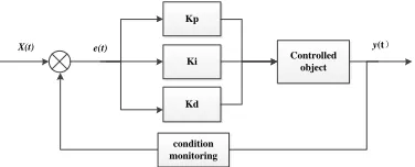
integrating factor, which can eliminate the steady state error, and Kd is the differential factor, which can accelerate the reaction of the system.
dt t de K dt t e K t e K
Fmac p i
d(12)
Fmac can be obtained from the Formula (11). The braking torque can be
calculated by the current motor state and compared with the torque of the demand braking torque, then the motor braking force is sent to motor control unit.
Kp Ki Kd
Controlled object
y(t)
e(t) X(t)
[image:8.612.214.402.236.312.2]condition monitoring
Figure 5. PID controller principle.
HYDRAULIC BRAKING
In the process of electro-hydraulic compound braking, hydraulic brake occupies a large proportion, single wheel can use one of the biggest ground braking force Fx and vertical force fluctuation, the largest ground braking force will be near the Fx volatility, design the goal of the hydraulic braking force is:
Fliq FbrakFmac
(13)
After the hydraulic power is obtained, the pressure value of each cylinder is calculated by the inverse braking model built by Simulink, and the vehicle model is passed to Carsim.
SIMULATION
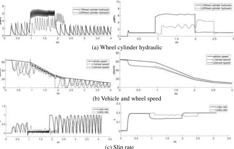
(a) Wheel cylinder hydraulic
(b) Vehicle and wheel speed
[image:9.612.102.484.85.328.2](c) Slip rate
Figure 6. Control effect of logic threshold ABS. Figure 7. Control effect of electro-hydraulic on split road composite ABS on split road.
As shown in Fig.6, the simulation results are control effect of logic threshold ABS on split road. In the low - high -low attached road, the results are similar with a homogenous pavement. The wheel cylinder hydraulic fluctuation frequency is high; when the adhesion coefficient of road jumps, the hydraulic pressure value will jump correspondingly. The wheel cylinder hydraulic of front wheel occurs about 4 Mpa fluctuation, the rear wheel cylinder hydraulic occurs about 2 Mpa fluctuations. The slip ratio jump when the road jumps; it can not keep stable and is not near optimal slip ratio. In conclusion, the traditional ABS control strategy has poor adaptability to the jump-road.
CONCLUSIONS
The traditional ABS control strategy Based on logic threshold to control the slip rate, fluctuation of hydraulic pressure occurs frequently which affects the vehicle braking stability. Reducing the hydraulic pressure fluctuation frequency is the key to improve the stability. In this paper, based on the compound control system of electric wheel motor, this paper puts forward a layered control strategy based on hydraulic stability. The upper part of the strategy uses pavement recognition to identify the current road and calculates the braking torque for slip rate control based on the state parameters of the vehicle. Lower part distributes the braking torque to the motor braking and hydraulic braking, motor braking control the slip rate by adjusting torque to realize the real-time control. The simulation results show that this strategy reduces the fluctuation frequency of the hydraulic pressure; ensures the stability of the braking and shortens the braking distance. The next step is to further verify the effectiveness of the strategy through the real car experiment .On the basis of this strategy, the synchronization improvement of braking efficiency and energy recovery can be realized.
REFERENCES
1. He Li. A study on the regenerative braking system of pure electric vehicle integrated control
strategy with ABS[D]. Wuhan: Wuhan University of Technology. 2012 In Chinese
2. Yimin Gao, Mehrdad Ehsani. Electronic Braking System of EV and HEV Integration of
Regenerative Braking, Automatic Braking Force Control and ABS [R].[s.n.]: SAE Paper, 2001.
3. Cheng Bin. Pure electric vehicle matching control strategy of regenerative braking system and
ABS[D]. Hefei: Hefei University of Technology. 2014 In Chinese
4. Peng D, Zhang Y, Yin C L, et al. Study on combined control of regenerative braking and antilock
braking system for hybrid electric vehicle [J]. International Journal of AutomotiveTechnology, 2008,9(6):749-757.
5. Chen Qing-zhang, He Ren, Shang Gao-gao. A research on integrated control of vehicle
regenerative braking based on ABS[J]. Automotive Engineering. 2008.30(04):301-304. In Chinese
6. Guo-zhu Zhao, Min-xiang Wei. A Research on the Double-closed-loop Control for Regenerative
Antilock Braking System in an Electric Vehicle Driven by Brushless DC Motor[J]. Automotive Engineering, 2013, 35(4):307-311. In Chinese
7. Zhi-sheng Yu, Automobile theory (The fifth edition)[M]. Beijing: Mechanical Industry Press,
2009. In Chinese
8. Wang B, Sun R Y, Liu X M. Road Surface Identification Approach Based on Vehicle Dynamic
Parameters[J]. Applied Mechanics & Materials, 2010, 44-47:3640-3646.
9. Fodor D, Enisz K, Doman R, et al. Tire road friction coefficient estimation methods comparison