© 2017, IRJET | Impact Factor value: 5.181 | ISO 9001:2008 Certified Journal | Page 2114
DESIGN OF MULTI ELECTRICITY GENERATOR USING SOLAR AND PIEZO
ELECTRIC TRANSDUCER
K.Aneelkumar
1, M.Sridhar
2, D.Swamy Durgaram
3, P.Rahul
4G.Snathosh Kumar
51,2,3,4,5
Student Department of EEE, Pragati Engineering College, Surampalem, A.P
---***---Abstract -
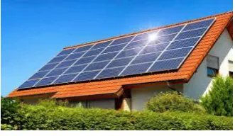
The objective of this project is to generate powercontinuously from the renewable energy resources. Here the renewable energy resources used in this project are solar power and rain water. Now-a-days using solar energy for the generation of electricity has become very popular. Particularly in the agricultural fields the usage of solar panels for electricity increasing day by day. The flaw in this concept is whenever there is sun, there will be solar energy production. But if there is no sun light i.e., during rainfall sufficient power will not be generated. For overcoming this problem this project is needed. This project is based on the principle of using hybrid mechanism of combining solar power technology with piezo electric power technology In this project, we will have hybrid panel i.e., one side it will have solar panel and other side it will have piezo electric plate. Based on the weather conditions, the plate will be rotated automatically using dc motors. So whenever the day is sunny, solar panel will be faced up and whenever there is rainfall, the piezo electric plate will be faced up. For sensing the sun, we are using an LDR and for detecting the rainfall we are using moisture sensor.
Key Words: Aurdino Microcontroller, LDR Sensor, Moisture Sensor, Piezo Electric Panel, Solar Panel
1. INTRODUCTION
In today’s rapidly increasing and randomly developing technological world, the ultimate need for sustainment of human race is Electricity. There are many ways in which the Electric energy can be stored, converted, and amplified for our use. To help in understanding the energy sources which plays an important role in the world’s future, it is required to familiarize with some of the history, theory, economics, and problems of the various types of energy. The energy sources have been split into three categories: fossil fuels, renewable sources, and nuclear sources. The fossil fuels here are coal, petroleum, and natural gas. The renewable energy sources are solar, wind, hydroelectric, ocean energy, and piezo energy. The nuclear-powered sources are fission and fusion.
1.1PROJECT OBJECTIVE
The purpose of this project is to generate power from multiple sources. This project we are using two main sources to generate power. They are solar and Piezo electric transducer LDR Sensor to sense light and moisture sensor to sense moisture.
1.2 EXISTING TECHINQUE
The name solar power is actually a little misleading. In fact, most of the energy known to man is derived in some way from the sun. The creation of solar panels typically involves cutting crystalline silicon into tiny disks less than a centimeter thick. These thin, wafer-like disks are then carefully polished and treated to repair and gloss any damage from the slicing process. After polishing, do pants (materials added to alter an electrical charge in a semiconductor or photovoltaic solar cell) and metal conductors are spread across each disk. Amorphous silicon solar panels are a powerful that differ in output, structure and manufacture than traditional photo-voltaic which use crystalline silicon. Silicon thin-film cells are mainly deposited by chemical vapour deposition (typically plasma-enhanced, PE-CVD) from silane gas and hydrogen gas.
1.3 PROPOSED TECHNIQUE
The piezoelectric effect, by which a material generates an electric potential in response to a temperature change, was studied by Carl Linnaeus and Franz Aepinus in the mid-18th century. Drawing on this knowledge, both René Just Haüy and Antoine César Becquerel posited a relationship between mechanical stress and electric charge; however, experiments by both proved inconclusive. The first demonstration of the direct piezoelectric effect was in 1880 by the brothers Pierre Curie and Curie. They combined their knowledge of piezoelectricity with their understanding of the underlying crystal structures that gave rise to piezoelectricity to predict crystal behavior, and demonstrated the effect using crystals of tourmaline, quartz, topaz, cane sugar, and Rochelle salt (sodium potassium tartrate tetrahydrate).
1.4 TYPES OF SOURCE OF POWER
1.4.1 Solar Power
© 2017, IRJET | Impact Factor value: 5.181 | ISO 9001:2008 Certified Journal | Page 2115 energy obtained through the use of solar panels. Although
the field of research dealing with this type of solar power is relatively new, one should bear in mind that man has known about the energy of the sun for thousands of years.
[image:2.595.81.247.162.258.2]
Figure 1.1: Solar panel
1.4.2 Piezo Electric Energy
Piezoelectricity is the electric charge that accumulates in certain solid materials (such as crystals, certain ceramics, and biological matter such as bone, DNA and various proteins) in response to applied mechanical stress. The word piezoelectricity means electricity resulting from pressure. Piezo means to squeeze or press, and which means amber, an ancient source of electric charge. The piezoelectric effect is understood as the linear electromechanical interaction between the mechanical and the electrical state in crystalline materials with no inversion symmetry. The piezoelectric effect is a reversible process in that materials exhibiting the direct piezoelectric effect (the internal generation of electrical charge resulting from an applied mechanical force) also exhibit the reverse piezoelectric effect.
Figure 1.2: Piezo electric Transducer
2. POWER GENERATION FROM SOLAR ENERGY
2.1 Current status
For several years, worldwide growth of solar PV was driven by European deployment, but has since shifted to Asia, especially China and Japan, and to a growing number of countries and regions all over the world, including, but not limited to, Australia, Canada, Chile, India, Israel, Mexico, South Africa, South Korea, Thailand, and
the United States. Worldwide growth of photovoltaic has averaged 40% per year since 2000 and total installed capacity reached 139 GW at the end of 2013 with Germany having the most cumulative installations.
2.1.1 Running Techniques
Solar power plants use one of two technologies:
Photovoltaic (PV) systems use solar panels, either on rooftops or in ground-mounted solar farms, converting sunlight directly into electric power. Concentrated solar power (CSP, also known as
"concentrated solar thermal") plants use solar thermal energy to make steam then that is converted into electricity by a turbine.[2]
3. POWER GENERATION FROM PIEZO-ELECTRIC
EFFECT
The pyroelectric effect, by which a material generates an electric potential in response to a temperature change, was studied by Carl Linnaeus and Franz Aepinus in the mid-18th century. Drawing on this knowledge, both René Just Haüy and Antoine César Becquerel posited a relationship between mechanical stress and electric charge; however, experiments by both proved inconclusive. The first demonstration of the direct piezoelectric effect was in 1880 by the brothers Pierre Curie and Curie. They combined their knowledge of pyroelectricity with their understanding of the underlying crystal structures that gave rise to pyroelectricity to predict crystal behavior, and demonstrated the effect using crystals of tourmaline, quartz, topaz, cane sugar, and Rochelle salt (sodium potassium tartrate tetrahydrate).
3.1 Mechanism
The nature of the piezoelectric effect is closely related to the occurrence of electric dipole moments in solids. The latter may either be induced for ions on crystal lattice sites with asymmetric charge surroundings (as in BaTiO3 and PZTs) or may directly be carried by molecular
groups (as in cane sugar). The dipole density or polarization (dimensionality [Cm/m3]) may easily be
calculated for crystals by summing up the dipole moments per volume of the crystallographic unit cell. Not all piezoelectric materials can be poled. Of decisive importance for the piezoelectric effect is the change of polarization P when applying a mechanical stress. The power from PIEZO Electric transducer is depending on: 1. the orientation of P within the crystal; 2. crystal symmetry; and 3. the applied mechanical stress. The change in P appears as a variation of surface charge density upon the crystal faces. For example, a 1 cm3 cube of quartz with 2 kN (500 lbf) of
[image:2.595.105.254.518.596.2]© 2017, IRJET | Impact Factor value: 5.181 | ISO 9001:2008 Certified Journal | Page 2116
3.2Actuators
Figure 3.2Metal disk with piezoelectric disk attached, used in a buzzer.
As very high electric fields correspond to only tiny changes in the width of the crystal, this width can be changed with better-than-imprecision, making piezo crystals the most important tool for positioning objects with extreme accuracy — thus their use in actuators. Multilayer ceramics, using layers thinner than 100 µm, allow reaching high electric fields with voltage lower than 150 V. These ceramics are used within two kinds of actuators: direct piezo actuators and Amplified piezoelectric actuators. While direct actuator's stroke is generally lower than 100 µm, amplified piezo actuators can reach millimeter strokes.
Loudspeakers: Voltage is converted to mechanical movement of a metallic diaphragm.
Piezoelectric motors: Piezoelectric elements apply a directional force to an axle, causing it to rotate. Due to the extremely small distances involved, the piezo motor is viewed as a high-precision replacement for the stepper motor.
Piezoelectric elements can be used in laser mirror alignment, where their ability to move a large mass (the mirror mount) over microscopic distances is exploited to electronically align some laser mirrors. By precisely controlling the distance between mirrors, the laser electronics can accurately maintain optical conditions inside the laser cavity to optimize the beam output.
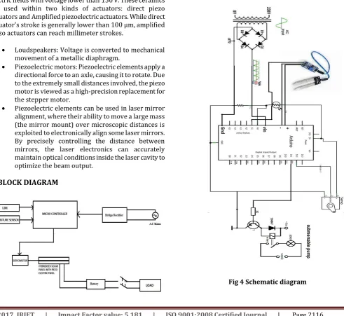
4. BLOCK DIAGRAM
4.1 BLOCK DIAGRAM OPERATION
The microcontroller is interfaced with light sensor and moisture sensor along with servomotor. So whenever the LDR senses the sunlight, it provides input
To microcontroller and microcontroller drives the servomotor which in turn rotates the hybridized panel and solar panel faces the sun and solar panel starts charging the battery.
Similarly whenever the moisture sensor senses the moisture from the rain water, it provides the input for microcontroller and microcontroller drives the servomotor so that hybridized panel and the Piezo electric panel faces up. The rain water hits the Piezo electric panel and due to Piezo electric effect, electricity is generated and battery starts changing.
5. SCHEMATIC DIAGRAM
[image:3.595.51.543.339.790.2]© 2017, IRJET | Impact Factor value: 5.181 | ISO 9001:2008 Certified Journal | Page 2117
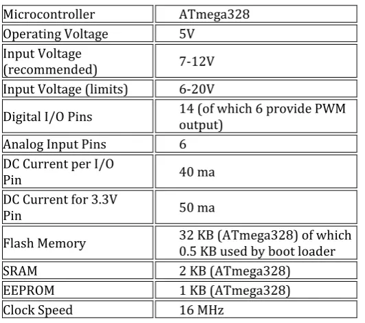
Table 1 Specifications other components Table
5.1. TECHNICAL SPECIFICATIONS
Fig 4 represents schematic diagram of proposed project. It consists of the following components.
1. Bridge rectifier 2. Arduino board 3. Moisture sensor
4. Servomotor with servo mechanism 5. Submersible pump load
1.
Bridge rectifier:
Bridge rectifier used for converting available ac supply to required dc .Converted output dc voltage is given to IC Circuits for obtaining required voltages. Example IC 7405, IC 7412, among these former will give dc voltage of 5V and later will give the output voltage of 12V.
2.
Arduino board:
It is the combination of preprogrammed micro controller, Adders, multiplexers, busbar connections and also contains AT commands for controlling the connected components or loads.
3.
Moisture sensor:
It is used for detecting the presence of wet conditions which can be used for further controlling purpose.
4.
Servomotor with servo mechanism:
Here in this project servomotor is used for rotating the solar panel along with the piezo electric transducer depending on
the command signals received from the Aurdino board.ATmega 328 is the Aurdino used in this project.
5.
Submersible pump load:
Here in our project used submersible pumps as loads to obtain the desired output.
[image:4.595.34.300.121.356.2]Table 1 show the ratings and technical specifications of different components used in our project. The complete hardware equipment we used are purely based on the requirement of the project.
Table 2 Specifications other components:
Bridge rectifier Diode IN4007/3A Moisture sensor 1kohm,operating voltage 5V DC motor 30 RPM,3KG Submersible
pumps 1000RPM,9V
Solar panel OC voltage 12V,1.2A
Transformer 230/12V,1A
RESULTS
The hybrid panel had rotated based on the weather condition i.e., when the LDR sensed the light with intensity the hybrid panel is rotated and solar side of the hybrid panel faced up as shown in Fig.5.1.Similarly when the moisture sensor sensed the moisture content, the hybrid panel is again rotated and the piezo electric panel is faced up as shown in the Fig.5.2
5.1. Implemented hardware:
[image:4.595.336.536.276.410.2] As the LDR senses the light with more intensity, the panel is rotated and the solar panel faces up.
Fig.5.1.Implemented hardware with solar panel at top Microcontroller ATmega328
Operating Voltage 5V Input Voltage
(recommended) 7-12V Input Voltage (limits) 6-20V
Digital I/O Pins 14 (of which 6 provide PWM output)
Analog Input Pins 6 DC Current per I/O
Pin 40 ma
DC Current for 3.3V
Pin 50 ma
Flash Memory 32 KB (ATmega328) of which 0.5 KB used by boot loader
SRAM 2 KB (ATmega328)
[image:4.595.315.558.567.748.2]© 2017, IRJET | Impact Factor value: 5.181 | ISO 9001:2008 Certified Journal | Page 2118 As the moisture sensor senses the moisture content, the
[image:5.595.313.557.57.566.2]panel is rotated and the piezo electric panel faces up.
Fig.5.2.Implemented hardware with Piezo electric board at top
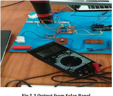
Fig.5.3 Output from Solar Panel
Table 3 Output voltages from the panel
S.NO PANEL NAME OUTPUT VOLTAGE (V) 1 Solar Panel 4.01 V
2 Piezo Electric
Panel 3.97 V
[image:5.595.44.278.124.304.2]
Fig.5.4 Output from Piezo Electric Panel
Table 4 Output values from sensors
S.NO Sensor Name Value before
sensing Value after sensing
1 LDR 101 953
2 Moisture
Sensor 1023 655
Fig.5.5 Results during light sensor sensing the light
[image:5.595.44.280.351.552.2]© 2017, IRJET | Impact Factor value: 5.181 | ISO 9001:2008 Certified Journal | Page 2119
6. CONCLUSIONS
The pre-study report has described that using the hybrid power generation i.e., solar power generation combined with power generation from piezo electric effect gave the conclusion that it provides path for obtaining continuous power generation from renewable energy resources based on weather conditions
7. FURTURE SCOPE
This project is in the first stage of using hybrid power generation concept. In this project, we used the solar panel fixed based on the concept of Electrical tracking of solar panel. But for the future extension the project, we are planning for the implementation of this project based on the concept of Mechanical tracking of solar panel so that we can utilize Maximum Power Point Tracking Technique and then we are able to provide the Maximum of solar power at any instant of time during daytime
REFERENCES
1. M. Birkholz (1995). "Crystal-field induced dipoles in heteropolar crystals – II. Physical significance". Z.Phys.B. 96(3):333340. Bib code: 1995ZPhyB..96..333 B.doi:10.100 7/BF01313055.
2. Damjanovic, Dragan (1998). "Ferroelectric, dielectric and piezoelectric properties of ferroelectric thin films and ceramics". Reports on Progress in Physics. 61 (9): 1267–
3. Holler, F. James; Skoog, Douglas A.; Crouch, Stanley R. (2007). "Chapter 1". Principles of Instrumental Analysis (6th Ed.). Cengage Learning. p. 9. ISBN 978-0-495-01201-6.