http://dx.doi.org/10.4236/wet.2015.61001
A Compact Wideband Dual-Polarized
Printed Antenna with Coaxial Feeds for
TD-SCDMA Application
Yujie Liu, Wei Tang, Yuehe Ge, Guogang Li
College of Information Science and Engineering, Huaqiao University, Xiamen, China Email: yuehe@ieee.org, liutld@126.com
Received 20 October 2014; revised 25 November 2014; accepted 29 December 2014
Copyright © 2015 by authors and Scientific Research Publishing Inc.
This work is licensed under the Creative Commons Attribution International License (CC BY). http://creativecommons.org/licenses/by/4.0/
Abstract
In this article, a low-profile wideband dual-polarized planar printed dipole antenna, fed by coaxial lines, is investigated for the TD-SCDMA operation. The antenna is composed of two printed dipoles, two pairs of feeding coaxial lines and a ground. The single-polarized planar printed rectangular dipole and petal dipole, with the similar configuration, are first studied, exhibiting the potential wideband operation. Two petal dipoles are then cross-arranged to design a dual-polarized planar printed antenna, giving a lower profile and a better bandwidth covering the Chinese TD-SCDMA band (1880 - 2400 MHz). The dual-polarized antenna is simply excited by two pairs of coaxial feeds. Simulated and measured results show that the antenna achieves a common impedance bandwidth of 42% at both ports, good isolation of more than 25 dB, stable radiation patterns and the gain of about 7 dBi over the operating bandwidth.
Keywords
Base Station Antenna, Dual Polarization, Petal Type Antenna, TD-SCDMA, Printed Dipole
1. Introduction
an-tennas and magneto-electric dipole anan-tennas have attracted much attention [5]-[10] for the development of wi-deband dual-polarized base station antennas. Wide bandwidth and good radiation performance are the common advantages for these antennas. In this paper, a planar petal-shape dipole antenna with coaxial feeding mechan-ism is developed for wideband applications. Two pairs of such planar printed dipole antennas with two DC grounded coaxial feeds and backed by a PEC ground form a wideband dual-polarized antenna element for base station antennas. The antenna was developed to cover the frequency band for the Chinese self-developed stan-dard Time Division Synchronous Code Division Multiple Access (TD-SCDMA) system, operated at frequency bands (A) 1880 - 1920 MHz, (B) 2010 - 2025 MHz and (C) 2300 - 2400 MHz. Advantages of this antenna in-clude low profile, wide bandwidth, dual polarization, high isolation and ease to fabricate and mount. Parametric study was performed and a prototype was built and tested to demonstrate the performance of the antenna.
2. Antenna with Coaxial Feeds Description
2.1. Planar Dipole with Coaxial Feeder
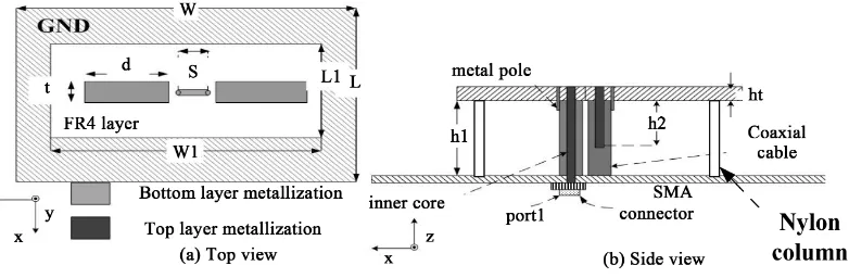
The configuration of the initial planar printed dipole investigated in this work is shown in Figure 1. It is com-posed of a rectangular printed dipole, a coaxial feeder connected to a SMA connector and a PEC ground. The planar rectangular dipole, with a dimension of d × t, is printed on the top surface of a FR4/Epoxy substrate, which is suspended on a PEC ground plane and supported by Nylon poles. The substrate has a height of h1, a dielectric constant of 4.4 and a thickness of 0.8 mm, as shown in Figure 1(a). The substrate and the ground have the dimensions of L1 × W1 and L × W respectively. The dipole is fed by a coaxial balun. Figure 1(b) shows the feeding mechanism. Two coaxial lines are placed between the substrate and the ground. The outer copper shields of both coaxial lines are connected to the PEC ground, as well as the dipole through two metal poles. One of inner copper cores is connected to a 50 Ω SMA connector underneath the ground and a small metallic strip, printed on the top surface of the substrate. Another copper core is an open stub and connected to the other end of the strip and has a length of h2 + ht. Compared to the conventional printed dipole antenna, the two copper cores and the small strip on the top surface of the substrate are served as the balun and the copper shields are the corresponding ground connected to the printed dipole. The antenna has a planar structure and an additional ground to increase the directivity above the ground.
The design of this planar printed dipole antenna with a coaxial feeding is similar to that of a conventional di-pole antenna. A λ/4 short-circuited conductor is needed to connect one of the λ/4 printed strips. The outer con-ductors or the copper shields of the coaxial line are employed as the λ/4 short-circuited conductor. Therefore, the length of the coaxial line, h1, should be about λ/4 of the operating frequency. The length of the open copper core, h2, should be about λg/4 (λg is the guided-wavelength in coaxial line) in order for the balun to feed the
planar dipole antenna. The dipole length, d, should be about λ1/4 (λ1 is the wavelength on the FR4 substrate).
[image:2.595.104.495.580.708.2]The antenna is designed for the wireless base station antennas operating at about 2 GHz. Based on the design strategy above, the dimensions of the planar dipole antenna are optimized and listed in Table 1. In the design, the parameter h1 and h2 are two important parameters to tune the impedance matching of the antenna. The pa-rameter h1 is normally chosen to be as small as possible, to keep a low profile. The length of the open copper core, h2, can be adjusted for good impedance matching. The simulated VSWRs for h1 = 50 mm and different h2 values, obtained from commercial software Anoft HFSS, are plotted in Figure 2.
Figure 2. VSWR and realized gain of the planar rectangular dipole antenna.
Table 1. Dimensions of the planar printed rectangular dipole antenna with a
coaxial feed (unit: mm).
W L W1 L1 S
150 150 80 40 5.2
d T h1 h2 ht
26 5 50 16 0.8
As can be seen, adjusting the length of the open copper core can minor tune the operating band and the im-pedance matching. The simulated realized gain for h2 = 16 mm, also plotted in Figure 2, is maintained about 6.7 dBi over the whole operating band, which is determined by VSWR < 2, ranging from 1.75 GHz to 2.32 GHz, about 28%.
2.2. Petal Dipole with Coaxial Feeder
Further study on the planar printed dipole antenna with a coaxial feed was carried out and it is found that the bandwidth can be improved by changing the shape of the printed dipole, without compromising the radiation performance. One of the examples is the planar printed dipole with a petal shape. Figure 3 shows the geometry of the petal dipole. It can be seen that the antenna geometry is similar to that in Figure 1, except for the shape of the dipole. The parameters of the petal dipole are optimized and the final dimensions are listed in Table 2. The simulated VSWR and realized gain are plotted in Figure 4. The bandwidth for VSWR < 2 is 35%, from 1.74 GHz to 2.48 GHz. Compared to that of the dipole in Figure 1, which is 28%, the bandwidth is improved by 7%. The realized gain is also improved a little, though it slightly decreases with frequency.
2.3. Dual-Polarized Planar Printed Dipole with Coaxial Feeder
[image:3.595.163.434.302.368.2]Figure 3. Configuration of the wideband planar printed petal dipole.
[image:4.595.88.539.651.721.2]Figure 4. VSWR and gain of the printed petal dipole antenna.
Figure 5. Geometry of the concerned dual-polarized planar printed antenna.
Table 2. Dimensions of the planar printed petal dipole antenna with a coaxial feed (unit: mm).
L W L1 W1 S wp
150 150 40 80 5.2 33.6
lp1 lp2 h1 h2 ht
metallic poles, as shown in Figure 5(c). Thus, the two dipoles can be cross-arranged and fed by two pairs of coaxial lines, exhibiting dual-polarization performance.
In the design, FR4/Epoxy substrate with the permittivity of 4.4 and a thickness of 1.5 mm is employed. The height (h1) of the substrate, the lengths of the two open copper cores and the dimensions of the dipoles deter-mine the impedance matching and its operating bandwidth. The target of the design is the wide bandwidth and the low profile of the antenna. Based on the simulation and optimization from HFSS, it is found that the antenna exhibits a better bandwidth and a lower profile, compared to the two single-polarized cases shown in Figure 1 and Figure 3 respectively. The reason might be the strong mutual coupling between the two dipoles. The final optimized dimensions of the dual-polarized design are listed in Table 3. It can be seen that the height (h1) of the substrate is only 32 mm, lower than those in the designs shown in Figure 1 and Figure 3. The VSWRs of the two ports of the dual-polarized planar printed dipole antenna, calculated using Ansoft HFSS, are plotted in Fig-ure 6. One can see that wide operating bands at the two ports, determined by VSWR < 2 and ranging from 1.54 GHz to 2.78 GHz and 1.6 GHz to2.8 GHz respectively, are obtained. The bandwidths at the two ports are 57.4% and 54.5% respectively and both cover the Chinese TD-SCDMA band (1880 - 2400 MHz). Compared to those of the single-polarized designs above, which are 28% and 35% respectively, the common bandwidth, which is about 54%, is significantly improved, due to the mutual coupling between the two dipoles.
The fabricated prototype for the designed dual-polarized printed dipole was measured using Vector Network Analyzer Agilent E8363C and the measured results are also plotted in Figure 6, for comparison. The measured common bandwidth for the two ports of the antenna are 42%, ranging from 1.76 GHz to 2.68 GHz. Figure 7 shows the simulated and measured isolations between the two ports, which are 30 dB and 25 dB over the whole operating bandwidth, respectively. The difference between simulations and measurements might come from the difficulty when tuning open copper cores and other unpredicted factors during the fabrication. The realized gain, calculated using Ansoft HFSS and shown in Figure 8, is maintained about 7 dBi over the bandwidth, for both ports. The antenna prototype is also measured and the measured gains for both ports are almost same. Therefore, only one measured gain curve is given in Figure 8. Figure 9 shows the prototype pictures of the proposed dual-polarization planar antenna. The radiation patterns are also measured and plotted in Figure 10. It can be seen that stable radiation patterns at 1.8 GHz, 2.2 GHz and 2.4 GHz are obtained.
Table 3. Dimensions of the dual-polarized printed antenna (unit: mm).
L W1 wp1 wp2 lp lp1
160 80 8 24 4.8 7.5
lp2 h1 h2 h3 ht S
22.5 32 16 21.5 1.5 5.2
Figure 6. Measured and simulated VSWRs for the dual-polarized planar printed
Figure 7. Measured and simulated isolation for the dual-polarized planar printed antenna excited by coaxial lines.
Figure 8. Gain of the dual-polarized planar printed antenna excited by co-axial lines.
(a)
(b)
(a) (b)
[image:6.595.89.537.540.708.2]Figure 10. Measured radiation patterns of the dual-polarized planar printed antenna in E and H
planes at 1.8 GHz, 2.2 GHz and 2.4 GHz, for Port 1 and Port 2, respectively.
3. Conclusion
[image:7.595.103.484.81.639.2]a petal dipole, with such configuration, have achieved bandwidths of 28% and 35% respectively. Two printed petal dipoles are then cross-printed on a FR4/Epoxy substrate, fed by two pairs of coaxial lines and backed by a PEC ground, forming a low-profile dual-polarized antenna for the TD-SCDMA operation. Due to the mutual coupling, the antenna has a lower profile (about 0.21λ at 2 GHz), a wider common bandwidth (42%), stable radiation patterns over the whole bandwidth and a stable gain of about 7 dBi. Additional advantages include simple structure, ease to fabricate, install, and be arrayed for TD-SCDMA base station antenna.
Acknowledgements
This research was supported by the centre university special funding project (JB-ZR1144), China, and Natural Science Foundation of Fujian Province (2011J01351), China, the Tongjiang Scholars Program, Fujian province, China, the Start-Up Program (11BS301) from Huaqiao University, China, Natural Science Foundation of Fujian Province (2012J01276), China, Xiamen Major Science and Technology Project (3502Z20131019), and Qua-nzhou Science and Technology Project (Z1424008), QuaQua-nzhou, Fujian province, China.
References
[1] Wong, H., Lau, K.L. and Luk, K.M. (2004) Design of Dual-Polarized L-Probe Patch Antenna Arrays with High Isola-tion. IEEE Transactions on Antennas and Propagation, 52, 45-52. http://dx.doi.org/10.1109/TAP.2003.822402
[2] Wu, B.Q. and Luk, K.M. (2009) A Broadband Dual-Polarized Magneto-Electric Dipole Antenna with Simple Feeds. IEEE Antennas and Wireless Propagation Letters, 8, 60-63. http://dx.doi.org/10.1109/LAWP.2008.2011656
[3] Secmen, M. and Hizal, A. (2010) A Dual-Polarized Wide-Band Patch Antenna for Indoor Mobile Communication Ap-plications. Progress in Electromagnetics Research (PIER), 100, 189-200. http://dx.doi.org/10.2528/PIER09112607
[4] Lian, R.N. and Zheng, S.F. (2014) A Single-Layer Wideband Dual-Polarized Antenna with High Isolation. Progress In Electromagnetics Research C, 49, 115-122. http://dx.doi.org/10.2528/PIERC14031904
[5] Adrian and Schaubert, D.H. (1987) Dual Aperture-Coupled Microstrip Antenna for Dual or Circular Polarization. Electronics Letters, 23, 1226-1228. http://dx.doi.org/10.1049/el:19870854
[6] Zhou, Z.W., Yang, S.W. and Nie, Z.P. (2007) A Novel Broadband Printed Dipole Antenna with Low Cross-Polariza- tion. IEEE Transactions on Antennas and Propagation, 55, 3091-3093.
http://dx.doi.org/10.1109/TAP.2007.908570
[7] Li, R.L., Wu, T. and Pan, B. (2009) Equivalent-Circuit Analysis of a Broadband Printed Dipole with Adjusted Inte-grated Balun and an Array for Base Station Applications. IEEE Transactions on Antennas and Propagation, 57, 2180- 2184. http://dx.doi.org/10.1109/TAP.2009.2021967
[8] Vallecchi, A. and Gentilli, G.B. (2005) Design of Dual-Polarized Series-Fed Microstrip Arrays with Low Losses and High Polarization Purity. IEEE Transactions on Antennas and Propagation, 53, 1791-1798.
http://dx.doi.org/10.1109/TAP.2005.846732
[9] Huang, Y.-H. and Zhou, S.-G. (2013) Compact and Wideband Dual-Polarized Antenna with High Isolation for Wire-less communication. Progress in Electromagnetics Research Letters, 38, 171-180.
http://dx.doi.org/10.2528/PIERL13020102