© 2017, IRJET | Impact Factor value: 5.181 | ISO 9001:2008 Certified Journal | Page 969
DESIGN OF COMMON HEADER LINE FOR REDUCTION OF PROCESS TIME IN
PUMP TESTING
V.Naveenprabhu
1,*,F.JustinDhiraviam
2, A.Vimal
3and K.Kumarrathinam
41,2,3 Assistant professor, Department of mechanical Engineering, Sri Eshwar College of engineering, Coimbatore, India.
4 Executive engineer, Enmas GB Power systems projects limited, Chennai, India.
---*****---
ABSTRACT
Groundwater is frequently chosen as the most suitable source of drinking water. Hence it is necessary to conduct various tests to analyze the various parameters while abstracting the water. Pumping tests are a practical way of obtaining the results pertaining to the water abstraction. Much of the specialized knowledge and technical expertise needed for this purpose can be gained from the standard literature. However, field operations in remote areas or in difficult conditions often require flexibility to solve technical problems. The end result should be a cost-effective facility capable of supplying water for many years. The main objective of the project is to test the operation of the pumping and monitoring equipment, to make sure that employed method is been a sophisticated, effective and efficient method which will bring down the process timing and manual labor. Industries plunged towards technological development such as automation, superior material management etc., which brings down the manual labor work and most important factor, Time. This work is also a technique which reduces the handling time and handling effort in the process of testing the pump for its specifications.
KEYWORDS:
pumping test, common header, delivery line and suction lineINTRODUCTION
A pump is a device that moves fluids (liquids or gases), or sometimes slurries, by mechanical action. Pumps can be classified into three major groups according to the method they use to move the fluid: direct lift, displacement, and gravity pumps. Pumps operate by some mechanism and consume energy to perform mechanical work by moving the fluid. Pumps operate via many energy sources, including manual operation, electricity, engines, or wind power, come in many sizes, from microscopic for use in medical applications to large industrial pumps.Mechanical
pumps serve in a wide range of applications such as pumping water from wells, aquarium filtering, pond filtering and aeration, in the car industry for water-cooling and fuel injection, in the energy industry for pumping oil and natural gas or for operating cooling towers. The every pump has to test the capacity before implement into in action of actual load.
Testing of pumps to check whether that it meets the manufacture specification is the area that needs improvement.The problem identified is the time taken for testing of the pump is quite long and work is found tedious, in addition to huge manpower is needed while mounting and demounting of the pumps.Since wide range of pumps are been tested, It is often found that the old method is time consuming and taken a dig at manual power.It is observed that the present method employed for the testing of pumps need improvisation.Currently separate suction line and delivery line are used for testing the pumps of suction separately for lengths 1”, 1.5”, 2”, 2.5” and for lengths 3”, 4”, 6”. Such a kind of design takes huge time in testing and also requires high man power.
LITERATURE REVIEW
Randall W. Whitesides, PE et alThere are many factors that affect the operation of a pump. Important factors are total head, speed, liquid properties, and physical arrangement/system connection. Included in the category of arrangement and connection are the suction conditions.
Excessive suction lift, shallow inlet submergence, or insufficient
© 2017, IRJET | Impact Factor value: 5.181 | ISO 9001:2008 Certified Journal | Page 970 process factors, with planning and foresight many
times the pump suction conditions can be optimized in the design stage.
Gokilakrishnan.g et al.[10] torque required to open the valve in the fluid system needs some separate external mechanical equipment for easier the operation of valve.
Naveenprabhu et al. [6] and [7] deals with the fluid flow over the closed pipe environment to enhance the fluid heat transfer characteristics nano sized materials like aluminium are mixed with the water by means of separate mechanical process of chemical decomposition to enhancement of thermal conductivity of water. These chemical composition will increase the density of water that result decrease the flow due to increase viscosity as well as pressure drop in flow.
Baskaran.s et al.[8] experimental setup has explained with help of ic engines with different fuel for the flow analysis of fuel through the different flow of diesel with different blending.
Saravanakumar.N et al. [9] nano materials is mixed with the cutting fluid used in the conventional as well as CNC machines for the efficient heat transfer, when introduction of these types of fluids in application main problem arising is the flow to application is not as original because of alter the mother fluid by some of the additives.
Sathiseelan.N et al. [11] Advanced materials exhibitvery excellent technical properties. However, the high costof both raw materials and processing limit their use.Advanced material such asnickel-base alloys, titanium alloys and stainless steel can beused
as the work piece in this type of welding and weldingparameters such as welding current.
EXPERIMENTAL SETUP
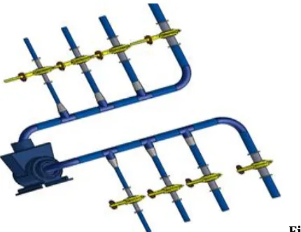
Theproposed common header line system is implemented in the pump testing line. Thebed used for the mounting of the pumps is the same as used before for testing individual pumps.
After mounting the pump, the common header line for suction and delivery are engaged to the pump’s suction and delivery port respectively. Thisdesign is used for both common header lines and the working of common header line is explained in the following:
Operation of 1” Pump
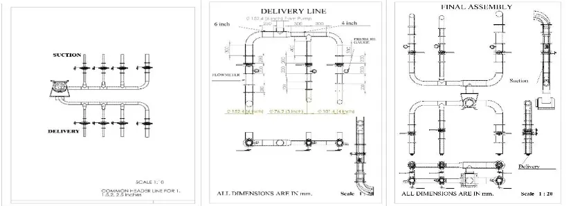
[image:2.612.35.449.533.682.2]When a pump of suction capacity 1” is to be tested, the 1” suction pump is mounted on the bed and the common header line assembly is mounted .When test is to be started the following arrangements are made . The valve engaged with the 1” suction line is opened and the 1.5”, 2”, 2.5” valves are closed. This, in turn makes the suction only through the 1” line. Eventually the flow takes place through the 1” suction line and flows through the common 2.5” header line and reaches the pump. From there by the pump mechanism, the water is fed into the delivery line. Similar to suction line the delivery line too comprises of valves. In the delivery line, the arrangement similar to suction is made i.e. 1” valve is opened, 1.5”, 2”and 2.5” are closed. And the flow measurement devices integrated with the 1” delivery line is used to find out different flow parameters.
© 2017, IRJET | Impact Factor value: 5.181 | ISO 9001:2008 Certified Journal | Page 971
Operation of 1.5” Pump
When a pump of suction capacity 1.5” is to be tested, the 1.5” suction pump is mounted on the bed and the common header line assembly is mounted .When test is to be started the following arrangements are made . The valve engaged with the 1.5” suction line is opened and the 1”, 2”, 2.5” valves are closed. This, in turn makes the suction only through the 1.5” line. Eventually the flow takes place through the 1.5” suction line and flows through the common 2.5” header line and reaches the pump. From there by the pump mechanism, the water is fed into the delivery line. Similar to suction line the delivery line too comprises of valves. In the delivery line, the arrangement similar to suction is made i.e. 1.5” valve is opened, 1”, 2” and 2.5” are closed. And the flow measurement devices integrated with the 1.5” delivery line is used to find out different flow parameters.
Operation of 2” Pump
When a pump of suction capacity 2” is to be tested, the 2” suction pump is mounted on the bed and the common header line assembly is mounted .When test is to be started the following arrangements are made . The valve engaged with the 2” suction line is opened and the 1”, 1.5”, 2.5” valves are closed. This, in turn makes the suction only through the 2” line.
Eventually the flow takes place through the 2” suction line and flows through the common 2.5” header line and reaches the pump. From there by the pump mechanism, the water is fed into the delivery line. Similar to suction line the delivery line too comprises of valves. In the delivery line, the rrangement similar to suction is made i.e. 2” valve is opened” and 1”, 1.5”, 2.5” are closed. And the flow measurement devices integrated with the 2” delivery line is used to find out different flow parameters.
Operation of 2.5” Pump
When a pump of suction capacity 2.5” is to be tested, the 2.5” suction pump is mounted on the bed and the common header line assembly is mounted .When test is to be started the following arrangements are made . The valve engaged with the 2.5” suction line is opened and the 1”, 1.5”, 2” valves are closed. This, in turn makes the suction only through the 2.5” line. Eventually the flow takes place through the 2.5” suction line and flows through the common 2.5” header line and reaches the pump. From there by the pump mechanism, the water is fed into the delivery line. Similar to suction line the delivery line too comprises of valves. In the delivery line, the arrangement similar to suction is made i.e. 2.5” valve is opened” and 1”, 1.5”, 2” are closed.
[image:3.612.56.271.515.681.2]Fig 2 : Final Assembly of Common HeaderLine 1” to 2.5”
© 2017, IRJET | Impact Factor value: 5.181 | ISO 9001:2008 Certified Journal | Page 972
FOR COMMON HEADER LINE OF LENGTH 3” TO 6” Operation of 3” Pump
When a pump of suction capacity 3” is to be tested, the 3” suction pump is mounted on the bed and the common header line assembly is mounted .When test is to be started the following arrangements are made . The valve engaged with the 3” suction line is opened and the 4”, 6” valves are closed. This, in turn makes the suction only through the 3” line. Eventually the flow takes place through the 3” suction line and flows through the common 4” header line and reaches the pump. From there by the pump mechanism, the water is fed into the delivery line. Similar to suction line the delivery line too comprises of valves. In the delivery line, the arrangement similar to suction is made i.e. 3” valve is opened, 4”and 6” is closed. And the flow measurement devices integrated with the 3” delivery line is used to find out different flow parameters.
Operation of 4” Pump
When a pump of suction capacity 4” is to be tested, the 3” suction pump is mounted on the bed and the common header line assembly is mounted .When test is to be started the following arrangements are made . The valve engaged with the 4” suction line is opened and the 3”, 6” valves are closed. This, in turn makes the suction only through the 3” line. Eventually the flow takes place through the 3” suction line and flows through the common 4” header line and reaches the pump. From there by the pump mechanism, the water is fed into the delivery line. Similar to suction line the delivery line too comprises of valves. In the
delivery line, the arrangement similar to suction is made i.e. 4” valve is opened, 3”and 6” is closed. And the flow measurement devices integrated with the 3” delivery line is used to find out different flow parameters.
Operation of 6” Pump
When a pump of suction capacity 6” is to be tested, the 6” suction pump is mounted on the bed and the common header line assembly is mounted .When test is to be started the following arrangements are made . The valve engaged with the 6” suction line is opened and the 3”, 4” valves are closed. This, in turn makes the suction only through the 6” line. Eventually the flow takes place through the 6” suction line and flows through the common 6” header line and reaches the pump. From there by the pump mechanism, the water is fed into the delivery line. Similar to suction line the delivery line too comprises of valves. In the delivery line, the arrangement similar to suction is made i.e. 6” valve is opened, 3”and 4” is closed. And the flow measurement devices integrated with the 6” delivery line is used to find out different flow parameters.
CALCULATION
CALCULATION OF ENERGY LOSSES
Kinematic Viscosity ⁄
Kinematic Viscosity ⁄
MAJOR ENERGY LOSS:
Darcy- Weisbach Equation,
Chezy’s Formula,
( ) √
- Loss of Head due to Friction
f- Coefficient of Friction which is a function of Reynolds number
Reynolds number=
, for Re < 2000 (Viscous Flow)
=
⁄ , for re varying from 4000 to
L– Length of Pipe
V- Mean Velocity of Flow d- Diameter of Pipe
P- Welded Perimeter of Pipe A- Area of Cross section of Pipe
© 2017, IRJET | Impact Factor value: 5.181 | ISO 9001:2008 Certified Journal | Page 973
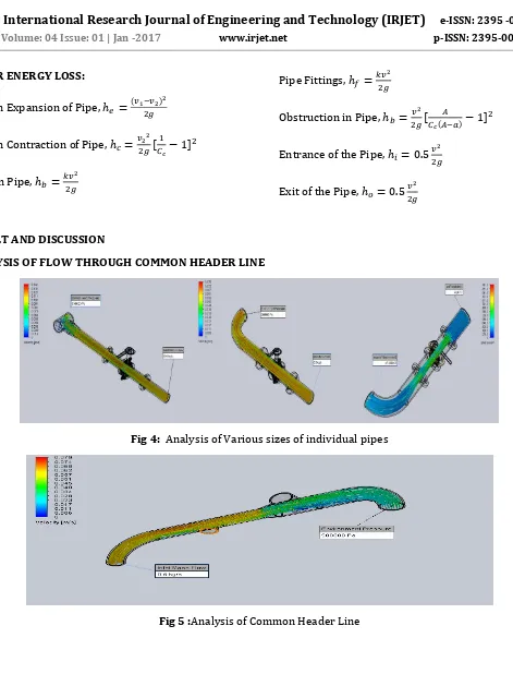
MINOR ENERGY LOSS:
Sudden Expansion of Pipe, ( )
Sudden Contraction of Pipe,
Bend in Pipe,
Pipe Fittings,
Obstruction in Pipe,
( )
Entrance of the Pipe,
Exit of the Pipe,
RESULT AND DISCUSSION
ANALYSIS OF FLOW THROUGH COMMON HEADER LINE
[image:5.612.68.539.37.655.2]Fig 4: Analysis of Various sizes of individual pipes
© 2017, IRJET | Impact Factor value: 5.181 | ISO 9001:2008 Certified Journal | Page 974
PROCESSTIMECALCULATION Table: 1 Present Method
NUMBER OF PUMPS
SETUP TIME (MOUNT +DEMOU
NT)
OPERA TION TIME
TOTA L TIME
NUMB ER OF LABO
URS
1 1 Hr 30
Mins 1 Hr 30 Mins 3 Hrs 4
4 6 Hrs 6 Hrs 12
Hrs
4
Max number of pumps tested/ Per day (8hrs) =2
Table: 2 Developed Method
COST ESTIMATION
Table3:Cost Estimation for 1” to 2.5” Common Header Line
COMPONENTS 1” 1.5” 2” 2.5” COST (IN
RUPEES)
PIPES (in meters) 1*86=86 1*139=139 1*186=186 3*300=900 1311
ELBOW - - - 2*125=250 250
TEE JOINT 2*25= 50 2*50= 100 2*80= 160 - 310
VALVE 2*212= 424 2*411= 822 2*629=1258 2*836=1672 4176 FLANGE 4*147= 588 4*196= 784 4*295=1180 4*447=1788 4340 REDUCER 1”*2.5”-
2*40= 80
1.5”*2.5”= 2*46= 92
2”*2.5”= 2*51= 102
- 274
[image:6.612.26.548.510.633.2]TOTAL COST Rs. 10661
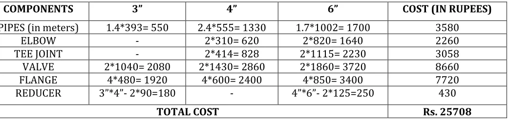
Table 4: Cost Estimation for 3” to 6” Common Header Line
COMPONENTS 3” 4” 6” COST (IN RUPEES)
PIPES (in meters) 1.4*393= 550 2.4*555= 1330 1.7*1002= 1700 3580
ELBOW - 2*310= 620 2*820= 1640 2260
TEE JOINT - 2*414= 828 2*1115= 2230 3058
VALVE 2*1040= 2080 2*1430= 2860 2*1860= 3720 8660
FLANGE 4*480= 1920 4*600= 2400 4*850= 3400 7720
REDUCER 3”*4”- 2*90=180 - 4”*6”- 2*125=250 430
TOTAL COST Rs. 25708
CONCLUSION
According to the International Labor Organization (ILO), “Ergonomics is defined as the application of human biological sciences in conjunction with
engineering sciences to the worker and his working environment, so as obtain maximum satisfaction for the worker which at the same time enhances productivity”.
NUM BER OF PUM
PS
SETUP TIME (MOUNT +DEMOU
NT)
OPER ATION
TIME
TOTA L TIME
NUMB ER OF LABO
URS
1 30 Mins 1 Hr 30 Mins
2 Hrs 2
4 2 Hrs 6 Hrs 8 Hrs 2 Max number of pumps tested/ Per day (8hrs)
© 2017, IRJET | Impact Factor value: 5.181 | ISO 9001:2008 Certified Journal | Page 975 Thus by using the Common Header Line, it becomes
very much easier for the workers to do pump testing without mounting and de-mounting the suction and delivery lines often.Hence the manual labor is reduced thereby reducing the process time and end result cost is also minimized.
REFERENCES
1. Dazhuan Wu, Leqinwang, ZangruiHao, Zhifeng Li and ZhirenBao (2010), ‘Experimental study of hydrodynamic performance of a cavitating centrifugal pump during transit operation’, Journal of Mechanical Science and technology, 575-582. 2. HildingBeij .K (1938), ‘Pressure losses for
fluid flow in pipe bends’, Part ofJournal of Research of the National Bureau of Standards, Volume 21.
3. Thandapani. P and Prasad. R (1995), ‘Centrifugal pump transientcharacteristics and analysis using the method of characteristics’, International Journal of Mechanical Science, 37 77-89.
4. NaveenPrabhu. V,SaravanaKumar. K,Suresh .T and Suresh.M,(2016) ‘Experimental investigation on tube-in-tubeheat exchanger using nanofluids’,ADVANCES in NATURAL and APPLIED SCIENCES,pages 272-278. 5. NaveenPrabhu. V and Suresh.M,(2015),’
Performance evaluation of tube-in-tube heat exchanger using nanofluids’ Applied Mechanics and Materials Vol. 787 (2015) pp 72-76.
6. Baskaran s and venkadesh s,(2015),’ Exergy analysis in ic engine using diesel blends as a fuel , International Journal of Applied Engineering Research ISSN 0973-4562 pp 5831-5836.
7. Saravanakumar.N ,Prabu. L ,Karthik.M and Rajamanickam .A(2014) ,’ Experimental analysis on cutting fluid dispersed with silver nano particles’ Journal of Mechanical Science and Technology,pp 645–651.
8. Gokilakrishnan.G ,Divya.S, Rajesh.R and Selvakumar.V,(2014),’ Operating torque in ball valves-a review’, International Journal For Technological Research In Engineering, ISSN (Online): 2347 – 4718,pp 311-315.
9. Sathiseelan.N and Baskaran.S, ( 2016) ,’ Optimization of welding parameters using plasma arc welding for SS316 material’, IRACST – Engineering Science and Technology: An International Journal,pp 26-31.