© 2017, IRJET | Impact Factor value: 6.171 | ISO 9001:2008 Certified Journal | Page 1323
Electromagnetic Assisted Takeoff for Various Aircraft’s Wingspans
Sambit Supriya Dash
SRM University, Department of Aerospace Engineering,
Kancheepuram, Chennai, Tamil Nadu, India.
---***---Abstract -
Aerospace Industry has evolved over the last century and is looking forward for more fuel efficient, cheaper, safer, simpler and convenient ways of flight stages. During take-off the rate of fuel consumption is observed to be maximum. By applying the concept of interpreting electromagnetism a remarkable rate of fuel consumption is reduced, which can be used in case of emergency due to lacking fuel or in case of an extended flight. In this paper the effectiveness of the concept is compared among different aircrafts having various wingspans by depicting the examples popular aircrafts. A complete setup of the electromagnetic system is described taking care of the weight constraints and operating conditions of an aircraft. By embedding a series of strong and controlled electromagnets (EMs) below the runway along and aside the center line maintaining the arrangement symmetry and another series embedded along the lateral axis of aircraft passing through consecutive spars of wing. The generated electromagnetic resultant force act on and through the wing-fuselage aerodynamic center for effective results. This concept can be used in upcoming future for making aviation more economic by reducing energy resource consumption.Key Words: Electromagnetism, Additional Lift, Fuel
Consumption, Emergency, Takeoff, Economic
1. INTRODUCTION
Since always the airways are considered as the safer, faster and better means of carriage and transportation. To keep this transportation standard, aircrafts go through regular quality tests, maintenances and repairs associated with lot of time and money. Aircrafts need more energy to generate power and use the air as a medium to travel which comes with feeding fuel to the power house of aircraft i.e. engine. During take-off phase of flight gaining the appropriate V speeds in time is very crucial. But when high-speed cross winds suddenly hit, the control surfaces and landing gears make a stable take-off possible, which requires more energy or fuel to overcome the drag. To compensate for this loss of fuel, by virtue of repulsive electromagnetic forces enough upward push has to be delivered so that it would counter some amount of lifting force generated by the wing. Thus low velocity during take-off enables the aircraft to lift up and achieve that speed. Less thrust is required than to the previous case which in turn needs less fuel flow rate to generate the required thrust. As in almost every case the position of throttle is maximum during the time of take-off, that means a lot of fuel is being consumed and this concept of interpreting electromagnetism (EM) deals with the take-off phase of flight. Thus a huge amount of fuel can be saved for the later phases of flight or for the emergency cases.
Here the electromagnetic waves can create attenuations for guidance and the navigation system. To counter this problem, the application of electromagnetic shielding can be used for an entire GNC system creating a barrier for electromagnetic frequencies.
Even in the case of fire on aircraft on the runway, behavior of EM is studied by researchers shows the spread rate of fire can be greatly affected and controlled by the electromagnetic (EM) field. This application can ensure the fire safety of aircraft. It could possibly be the safest, cheapest, most feasible and most effective method for airways.
2. MODEL OF NOTION
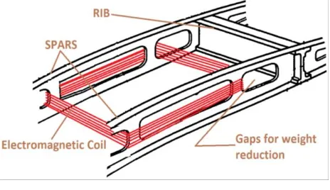
To install the EMs good conducting insulated copper wire is required. To setup EM is the aircraft the soft iron cores are not required to reduce weight. Permalloy could be used as the core of underground EM. The wing spars have gaps for weight reduction and the horizontal members of the spars hold around the EM coil. An accurate controlling mechanism is required to turn on and off and to set the value of current providing to the EM on the runway the ground staff and on the pilot controlled aircraft during takeoff and landing.
[image:1.595.308.555.552.757.2]The consecutive spars inside the wing are embedded with electromagnetic coils by taking care of structural constraints of the spars. These electromagnetic (EM) coils acts as a bar magnet and its strength and polarity can be controlled by varying current which is handled by the pilot. The complementary electromagnets are arranged symmetric under the runway and about the center line.
© 2017, IRJET | Impact Factor value: 6.171 | ISO 9001:2008 Certified Journal | Page 1324 Figure 2: Model of electromagnetic coil through two spars
together
3. APPLICATION OF THE NOTION ON THE MODEL
During takeoff the aerodynamic lift generated by wing of aircraft is given in equation (1).
(1) To reach the velocity ‘ ’, thrust ‘ ’ is required to be produced by engine. The takeoff velocity can be approximated in the terms of takeoff thrust by equation (2).
(2)
Strengths of electromagnets on the aircraft and electromagnets under the runway are given by equation (3) and equation (4), respectively.
(3)
(4)
By fundamental equation of force between two electromagnets, the generated force on the aircraft is given in equation (5), where ‘ ’ is the permeability in free space and ‘ ’ is the distance of wing from the runway surface.
(5)
During takeoff, pilot turns on aircraft’s EMs with positive polarity to create a repulsive EM force which can take a part of aerodynamic lift’s role. Hence, aerodynamic lift is reduced by ‘ ’ thus reducing the aircraft’s takeoff velocity ‘ ’ and thrust ‘ ’ to reach that velocity by aircraft. The velocity is finally required ‘ ’ to produce same aerodynamic lift by wing after applying the concept of EM is given in equation (6).
(6)
Required thrust ‘ ’ produced to reach velocity ‘ ’ is given by equation (7).
(7)
To maintain the consistency of the engine parameter Thrust Specific Fuel Consumption (TSFC), ‘ ’. With decrement of thrust required there must be reduction of fuel flow rate ‘ ’ to combustion chamber. The reduced fuel flow rate ‘ ’ by applying concept of EM is given in equation (8).
(8)
Rewriting the expression for ‘ ’ by substituting the terms from equations (5), (6) and (7) in equation (8), we produced equation (9) where ‘ ’.
(9)
Three aircrafts having different wingspans are considered as the examples for expressing the concept, its approach and its effectiveness.
Here case of the runway, EMs are embedded underground the size should be large enough to generate an effective electromagnetic force. For this case, along the width of the runway the best possible EM setup is of quantity 10 of radius 2.5 m each for effective functioning. The strength of one underground EM is calculated using equation (4).
Here, we have taken 30 m length of electromagnet, 30,000 turns, radius 2.5 m and a 15 A current supply.
In this paper a novel non-dimensional parameter is produced as ‘SRD Number’ denoted by ‘ ’ to check the application efficiency for an aircraft i.e.
(10) SRD Number comprises of four distinct zones.
© 2017, IRJET | Impact Factor value: 6.171 | ISO 9001:2008 Certified Journal | Page 1325
2.
ξ ∈ (1,14) : This region signifies that this EM configuration could be embedded to the aircraft with less effectiveness.3.
ξ ∈ (14,50) : This region signifies that the EM configuration is perfect for this aircraft.4.
ξ ∈ (50, ) : This region signifies that the EM configuration would be most effective for the aircraft.3.1 Large Size Wingspan
First aircraft for example is Airbus A330. As per its specificationsand considering during takeoff. We got,
.
As the wingspan = 60 m, 25 EMs with radius of 1.2 m are possible for setup, but we are taking 20 EMs with radius of 1.2 m for setup with proper clearance and arrangements. The chosen radius is 1.2 m because it is the best possible dimension to embed into and its square is proportional with generated EM force
.
Here, we have taken 10 EMs of 70 cm in length, 650 turns, 5A current supply and radius of 1.2 m. For both sides of the wing,
Here the 60 m wingspan can cover over 10 underground EMs. So strength of 10 EMs along the runway width is ‘ ’ given below.
[image:3.595.322.533.405.620.2]By substitution of these values in equation (5) and considering the only variable ‘r’ and plug the value of constants and the previously calculated values of the strength of aircraft EMs and under the runway we got:
Table 1. Force generation with the variation of distance of wing and runway surface
Distance of separation between two poles
(in m)
Upward repulsive lifting
force by EMs, (x105 ) (in N)
Contribution of the uplifting repulsive forces to the lifting
force (% of Lwing)
7 11.135 4.23692
8 8.5253 3.2439
9 6.736 2.563
10 5.456 2
15 2.4249 0.9
20 1.36404 0.5
25 0.87298 0.3334
Table 1 shows the behavior of electromagnetic forces as the aircraft is moving farther from the runway. This scenario comes into picture because during takeoff the aircraft is lifting up and going forward hence the electromagnets are embedded with the spars moving away from the electromagnets present under the runway. In the case of standing aircraft, the height of the wing from the ground is about 7 m. Here we have neglected the separation distance of the tip of the underground EM and the runway surface.
To know the distance from the runway where the electromagnetic force is minimum, we assumed the minimum contribution of electromagnetic force to the lift by the wing to be 0.001% of the aerodynamic lift. By using equation (1), we calculated the distance of wing from runway:
We got the minimum and maximum distance of wing of Airbus A330 from the runway where we can have the maximum and minimum value of electromagnetic forces’ contribution to the lift by wing. And the range of the usage is 7 to 455 m, respectively.
Chart 1. Graphical representation of Table 1
© 2017, IRJET | Impact Factor value: 6.171 | ISO 9001:2008 Certified Journal | Page 1326 (11)
(12)
After the application of electromagnetism, the lift to takeoff is reduced by 4.23692% by the contribution of electromagnetic force to the lift by wing on the runway during takeoff.
After applying the EM concept the aerodynamic lift required ‘ ’, the velocity required ‘ ’ to generate the required lift and the thrust required ‘ ’ to reach the velocity required ‘ ’ are calculated.
To calculate the drag force at the required velocity, first by calculating the drag force at maximum velocity from equation (11), we can get the approximate value of coefficient of drag.
The aircraft maximum drag force by using required velocity is estimated to be 176208.9526 N. And from equation (11), we got the equation for thrusts at ‘ ’:
The noted TFFC value is 0.565 lb/ (h·lbf) or
1.59651372e (-5) Kg/ (N.s) and .
For the value of mass fuel flow rate at required thrust with EM concept ‘ ’:
The change of mass fuel flow rate can be calculated by equation (12):
(13) It led to consumption of 5.941149047% of fuel during takeoff when the fuel consumption was supposed to be maximum. We can use it for any kind of emergency purposes or for the benefit on the basis of economy.
This concept’s complete setup on this aircraft carries about 800 Kg that is only 0.439% of the loaded weight of the aircraft.
This setup’s SRD Number ‘
ξ
’ is 13.534 which signifies this setup could be done but it would fetch not much effectiveness.3.2 Medium Size Wingspan
Second aircraft for example is Yakovlev Yak-40. As per its specificationsand considering during takeoff.
We got,
As the wingspan = 25 m, 18 EMs with radius of 0.65 m are possible for setup, and the reasons are same as for the previous example.
Here, we have taken 10 EMs of 0.63 m in length, 600 turns, 3A current supply and radius of 0.65 m. For both sides of the wing,
Here the span can cover only 5 Ems of the same runway.
So ‘ ’ is changed as per 5 Ems,
[image:4.595.308.555.499.783.2]By substitution of these values in equation (5) and considering the only variable ‘r’ and plug the value of constants and the previously calculated values of the strength of aircraft EMs and under the runway we got:
Table 2. Force generation with the variation of distance of wing and runway surface
Distance of separation between two poles (in m)
Upward repulsive lifting
force by EMs, (x105) (in N)
Contribution of the uplifting repulsive forces to
the lifting force (% of Lwing)
1.8 5.910844392 58.65
2 4.787783958 52.788
3 2.127903981 23.4614
3.5 1.563358027 17.2369
4 1.196945989 13.197
4.5 0.945751027 10.4272279
5 0.7660454332 8.4461
6 0.5319759953 5.865344
7 0.3908395067 4.3092325
8 0.2992364973 3.2993
9 0.2364337757 2.60682
10 0.1915113583 2.111524
11 0.1582738498 1.7450611
12 0.132994 1.4663361
13 0.11332 1.24942
© 2017, IRJET | Impact Factor value: 6.171 | ISO 9001:2008 Certified Journal | Page 1327 Table 2 shows the behavior of EM forces as the aircraft is
moving farther from the runway. In the case of standing aircraft, the height of the wing from the ground is about 1.8 m. Here we have neglected the separation distance of the tip of the underground EM and the runway surface.
By proceeding as in the previous example we found:
We got the minimum and maximum distance of wing of Yakovlev Yak-40 from the runway where we can have the maximum and minimum value of electromagnetic forces’ contribution to the lift by wing. And the range of the usage is 1.8 to 459.51 m, respectively.
In Yakovlev Yak-40, three Ivchenko AI-25 are used to produce thrust (T). Due to the presence of the opposing agent to thrust i.e. drag force (D), the thrust produced by the engines never equalizes with the thrust of whole aircraft. The maximum thrust can be produced by this power plant is 14679 N and TSFC is 0.575 lb/ (h·lbf). By using the equations (11) and (12), we followed previously used ways and got the following. The lift to takeoff is reduced by 58.65% by the contribution of electromagnetic force to the lift by wing on the runway during takeoff.
To calculate the drag force at the required velocity, first by calculating the drag force at maximum velocity from equation (11), we can get the approximate value of coefficient of drag.
Chart 2. Graphical representation of Table 2
The aircraft maximum drag force by using required velocity is estimated to be 8836.5874 N. And from equation (11), we got the equation for thrusts at ‘ ’:
The observed TFFC value is 0.575 lb/ (h·lbf) or 1.6247706e (-5) Kg/ (N.s) and
For the value of mass fuel flow rate at required thrust with EM concept ‘ ’:
By using equation (13) we came to know that it led to consumption of 58.7% of fuel during takeoff when the fuel consumption was supposed to be maximum. We can use it for any kind of emergency purposes or for the benefit on the basis of economy.
This concept’s complete setup on this aircraft carries about 342.2106 Kg that is only 2.8518% of the loaded weight of the aircraft which is little more than the large size wingspan’s. This setup’s SRD Number ‘
ξ
’ is 20.5835 which signifies this setup could be done and with optimum effectiveness.3.3 Small Size Wingspan
Third aircraft for example is Eclipse 500. As per its specificationsand considering during takeoff. We got,
As the wingspan = 11.4 m, 8 EMs with radius of 0.68 m are possible for setup, and the reasons are same as for the previous example.
Here, we have taken 8 EMs of 0.23 m in length, 220 turns, 3A current supply and radius of 0.68 m. For both sides of the wing,
Here the span can cover only 2 Ems of the same runway.
So ‘ ’ is changed as per 2 Ems,
© 2017, IRJET | Impact Factor value: 6.171 | ISO 9001:2008 Certified Journal | Page 1328 Table 3. Force generation with the variation of distance of
wing and runway surface
Distance of separation between two poles
(in m)
Upward repulsive lifting
force by EMs, (in N)
Contribution of the uplifting repulsive forces to the lifting
force (% of Lwing)
0.8 146130.22 64.41
0.9 115460.9 50.895
1 93523.34 41.23
1.1 77292.02 34.07
1.2 64946.76 28.63
1.5 41565.93 18.32
1.7 32361.02 14.26
1.9 25906.74 11.19
2 23380.84 10.306
2.5 14963.73 6.596
3.0 10391.48 4.58
3.5 7634.56 3.37
4.0 5845.208 2.58
4.5 4618.437 2.036
5.0 3740.9336 1.649
5.5 3091.68 1.36
6.0 2597.87 1.15
7 1908.639 0.84
8 1461.302 0.644
9 1154.609 0.51
10 935.23 0.41
13 553.39 0.24
15 415.659 0.18
17 323.61 0.14
20 233.81 0.1
25 149.637 0.066
30 103.915 0.046
Table 3 shows the behavior of EM forces as the aircraft is moving farther from the runway. In the case of standing aircraft, the height of the wing from the ground is about 0.8 m. Here we have neglected the separation distance of the tip of the underground EM and the runway surface. By proceeding as in the previous example we found:
We got the minimum and maximum distance of wing of Eclipse 500 from the runway where we can have the maximum and minimum value of electromagnetic forces’ contribution to the lift by wing. And the range of the usage is 0.8 to 203.00 m, respectively.
In Eclipse 500, two Pratt and Whitney are used to produce thrust (T). Due to the presence of the opposing agent to thrust i.e. drag force (D), the thrust produced by the engines never equalizes with the thrust of whole aircraft. The maximum thrust can be produced by this power plant is 13 kN and TSFC is 0.50 lb/ (h·lbf). By using the equations (11) and (12), we followed previously used ways and got the following. The lift to takeoff is reduced by 64.41% by the contribution of electromagnetic force to the lift by wing on the runway during takeoff.
To calculate the drag force at the required velocity, first by calculating the drag force at maximum velocity from equation (11), we can get the approximate value of coefficient of drag.
The aircraft maximum drag force by using required velocity is estimated to be 6125.442281 N. And from equation (11), we got the equation for thrusts at ‘ ’:
The observed TFFC value is 0.50 lb/ (h·lbf) or
1.41577778 e (-5) Kg/ (N.s) and
Chart 3. Graphical representation of Table 3
© 2017, IRJET | Impact Factor value: 6.171 | ISO 9001:2008 Certified Journal | Page 1329 By using equation (13) we came to know that it led to
consumption of 65.5549% of fuel during takeoff when the fuel consumption was supposed to be maximum. We can use it for any kind of emergency purposes or for the benefit on the basis of economy.
This concept’s complete setup on this aircraft carries about 57.8375 Kg that is only 0.3731% of the loaded weight of the aircraft which seems to be the most effective type of aircraft for EM concept application.
This setup’s SRD Number ‘
ξ
’ is 175.703 which clearly justifies that this is much more effective configuration than other examples.Chart 4. Showing the trend of the EM effect by fuel consumption rate with the aircrafts’ varying wingspan size
Chart 5. Showing the trend of the EM effect by SRD Number with aircrafts’ varying wingspan size
The charts 4 and 5 clearly depicts that usage of EM for the case of small size aircraft (low weight and thick wing) are remarkably effective and beneficial.
4. CONCLUSIONS
This work was carried out specifically for the takeoff phase to investigate the effect of electromagnetism on the concept aircraft and by various calculations and observations are expressed through examples. Finally the conclusions can be drawn as follows:
1. Contribution as a fraction of aerodynamic resultant force to lower the aerodynamic lift requirement. The EM application effectiveness on aircrafts is in following ascending order of large, medium and small size wingspan aircrafts, respectively.
2. Consumption of significant fuel flow rate to combustion chamber with the EM concept. The same trend of EM effectiveness is followed for the fuel consumption during takeoff.
3. A relation is produced relating fuel flow rate, electromagnets’ specifications, current supply and distance of aircraft from ground in equation (9). Which is applicable for any setup of EMs on aircraft and EMs under the runway.
4. A non-dimensional parameter is produced as SRD Number ‘
ξ
’ to check the application efficiency for the aircraft given in equation (10). This could be a major parameter for upcoming generations’ aviation.REFERENCES
[1] Nishanth Murugan, Mohammed Niyasdeen
Nejaamtheen, ad S. Sounder Rajan, “Conceptual Design of an Aircraft with Maglev Landing System”. International Journal of Aerospace and Mechanical Engineering, Vol:7, No:7, 2013.
[2] EMI Shielding: Methods and Materials-A Review by S.
Geetha, Konda Kannan Satheesh Kumar, Chepuri R. K. Rao, M. Vijayan, D.Dinesh C.Chandra Trivedi. Journal of Applied Polymer Science 112(4):2073 – 2086. May 2009.
[3] Magnetic Flame Spread by Poorva Shrivastava, A. Vinoth
Kumar, Pratik Tiwari, Vinayak Malhotra. IJAIEM, Volume 5, Issue 9, September 2016 ISSN 2319 – 4847.
[4] Electromagnetic Field Theory by Bo Thide.
[5] Fundamentals of Electromagnetism: Vacuum
© 2017, IRJET | Impact Factor value: 6.171 | ISO 9001:2008 Certified Journal | Page 1330 Sambit Supriya Dash, born in Odisha,
India. He is currently pursuing undergraduate course in Aerospace Engineering from SRM University, Chennai. He is highly enthusiastic in engineering, exploring science and applying the knowledge in real case scenarios.