© 2018, IRJET | Impact Factor value: 6.171 | ISO 9001:2008 Certified Journal | Page 2451
MODAL ANALYSIS AND OPTIMIZATION OF TILE CUTTER BLADE
USING FEA
Kailas Pathade
1, Akash Desai
2, Bhagyashri Dhanagar
3, Swapnil Kadam
4, Rohit Patil
5, Amol Patil
61Assistant Professor of mechanical department, Dr. A. D. Shinde College of Engineering, Gadhinglaj-416502, Maharashtra, India
2,3,4,5,6 B.E. of mechanical department, Dr. A. D. Shinde College of Engineering, Gadhinglaj-416502, Maharashtra, India
---***---Abstract
- In the cutting operation Circular tile cuttershaving uniform radial cracks are widely used. Cutters ar accustomed cut various materials to a needed size or form. they are available in an exceedingly variety of various forms, from basic manual devices to advanced attachments for power tools. Unwanted noise, vibration and accidental failure related to the cutting method became a crucial economic and technological side within the trade. The statistics of natural frequencies of elements is of exceptional hobby within the observe of the response of systems to various excitations. In this study, natural frequencies will be evaluated in desired frequency ranges of cutter mechanism. Mode shapes at various natural frequencies will be evaluated using FEA results, CATIA V5 software will be used to design various existing blades and modification will be carried out as per results. Optimization to minimize the weight of circular tile cutter and thereby reducing the material cost. Conclusion and future scope will be suggested.
Keywords -tile cutter, natural frequencies, Mode shapes, Optimization.
1. INTRODUCTION
Its miles general that the presence of cracks will have an effect on the dynamic behavior of the vibrating plate. Like a tangle is state-of-the-art due to it mixes the arena of vibration evaluation and fracture mechanics. circular cutters having homogeneous radial cracks place unit broadly employed for slicing mechanism. The records of natural frequencies of parts is of best hobby inside the have a look at of response of structures to numerous excitations. circular slicing tool may be a plate of circle having hole at middle that fastened at internal facet with unfastened at border for its dynamic feedback [1].
In tile cutting operation only one type of cutter is selected. People are getting trouble by using that cutter with respect to vibration point of view. Vibrations are creating in tile cutting operation. From the same sample, cutters are selected with respect to different changes so that we comment on vibration and natural frequency. There many parameters required to consider for minimize vibration in tile cutter. Which contain the increment in no. radial crack; increment the length of the radial crack, slot end whole diameter, the geometry of cutter tooth, material selection,
adding damping material, enlargement of stress concentration holes, applying mass concentration. The primary purpose of modification of such tile cutter beside from minimization of vibration is to allow thermal expansion during the cutting process without the development of circumferential stresses. Often in practice, a hole is cut at the end of slots in order to relieve the radial stress introduced by the slot which can cause by cracking[2].
2. MODELING OF CIRCULAR TILE CUTTER
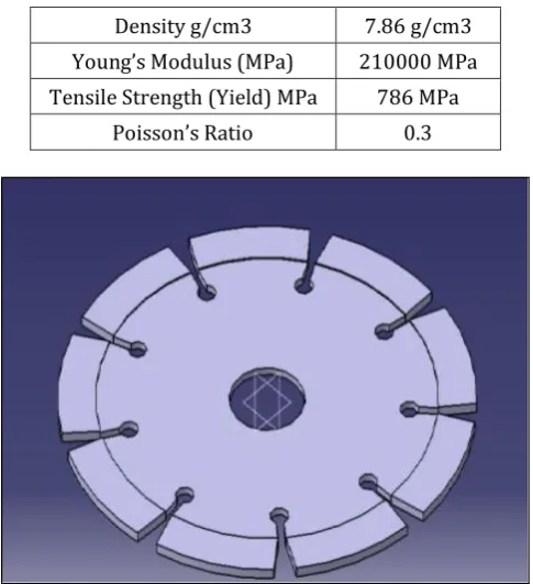
[image:1.595.313.556.437.703.2]A basic tile cutter modeled in CATIA whose outer diameter is 110 mm and inner diameter or hole is of 20 mm. thickness of 2 mm up to 75 mm and 1.5 mm at outer region it has 9 cuts [3]
Table -1: Material Properties
Density g/cm3 7.86 g/cm3
Young’s Modulus (MPa) 210000 MPa
Tensile Strength (Yield) MPa 786 MPa
Poisson’s Ratio 0.3
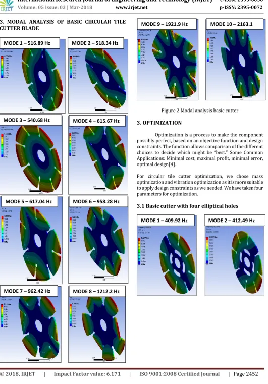
© 2018, IRJET | Impact Factor value: 6.171 | ISO 9001:2008 Certified Journal | Page 2452 3. MODAL ANALYSIS OF BASIC CIRCULAR TILE
[image:2.595.37.569.45.806.2]CUTTER BLADE
Figure 2 Modal analysis basic cutter
3. OPTIMIZATION
Optimization is a process to make the component possibly perfect, based on an objective function and design constraints. The function allows comparison of the different choices to decide which might be “best.” Some Common Applications: Minimal cost, maximal profit, minimal error, optimal design[4].
For circular tile cutter optimization, we chose mass optimization and vibration optimization as it is more suitable to apply design constraints as we needed. We have taken four parameters for optimization.
3.1 Basic cutter with four elliptical holes MODE 1 – 516.89 Hz
MODE 3 – 540.68 Hz
MODE 2 – 518.34 Hz
MODE 4 – 615.67 Hz
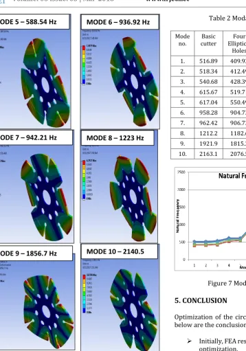
MODE 10 – 2163.1 Hz
MODE 9 – 1921.9 Hz
MODE 8 – 1212.2 Hz MODE 7 – 962.42 Hz
MODE 6 – 958.28 Hz MODE 5 – 617.04 Hz
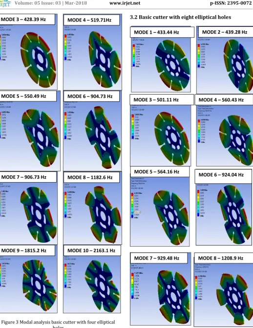
© 2018, IRJET | Impact Factor value: 6.171 | ISO 9001:2008 Certified Journal | Page 2453 Figure 3 Modal analysis basic cutter with four elliptical
holes
3.2 Basic cutter with eight elliptical holes
MODE 3 – 428.39 Hz MODE 4 – 519.71Hz
MODE 10 – 2163.1 Hz MODE 9 – 1815.2 Hz
MODE 8 – 1182.6 Hz MODE 7 – 906.73 Hz
MODE 6 – 904.73 Hz MODE 5 – 550.49 Hz
MODE 4 – 560.43 Hz MODE 1 – 433.44 Hz
MODE 3 – 501.11 Hz
MODE 2 – 439.28 Hz
MODE 7 – 929.48 Hz
MODE 5 – 564.16 Hz MODE 6 – 924.04 Hz
© 2018, IRJET | Impact Factor value: 6.171 | ISO 9001:2008 Certified Journal | Page 2454 Figure 4 Modal analysis basic cutter with eight elliptical
holes
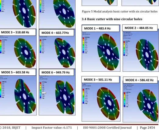
[image:4.595.40.563.366.794.2]3.3 Basic cutter with six circular holes
Figure 5 Modal analysis basic cutter with six circular holes
3.4 Basic cutter with nine circular holes MODE 9 – 1842.4 Hz MODE 10 – 2126.9 Hz
MODE 1 – 499.64 Hz
MODE 3 – 518.68 Hz
MODE 2 – 501.3 Hz
MODE 4 – 602.77Hz
MODE 10 – 2166.9 Hz MODE 9 – 1894.7 Hz
MODE 8 – 1231 Hz MODE 7 – 959.6 Hz
MODE 6 – 949.79 Hz MODE 5 – 603.58 Hz
MODE 1 – 483.4 Hz
MODE 3 – 501.11 Hz
MODE 2 – 484.05 Hz
© 2018, IRJET | Impact Factor value: 6.171 | ISO 9001:2008 Certified Journal | Page 2455 Figure 6 Modal analysis basic cutter with nine circular
holes
4. EFFECT OF OPTIMIZATION
[image:5.595.54.413.61.573.2]For above five models, we do modal analysis and the result. For frequencies are tabulated as shown below we observe that all cutter model gives frequencies more than the basic frequency of cutter so vibrations will get optimized. The things are elliptical eight holes give maximum weight reduction that is 8.2 % but according to manufacturing constraints, it will not economical. So we have taken circular nine holes for mass reduction of tile cutter.
Table 2 Modal analysis comparison
Mode
no. cutter Basic Elliptical Four Holes Eight Elliptical Holes Six Circular Holes Nine Circular Holes 1. 516.89 409.92 433.44 499.64 483.4 2. 518.34 412.49 439.28 501.3 484.05 3. 540.68 428.39 447.87 518.68 501.11 4. 615.67 519.71 560.43 602.77 586.42 5. 617.04 550.49 564.16 603.58 588.54 6. 958.28 904.73 924.04 949.79 936.92 7. 962.42 906.73 929.48 959.6 942.21 8. 1212.2 1182.6 1208.9 1231. 1223. 9. 1921.9 1815.2 1842.4 1894.7 1856.7 10. 2163.1 2076.5 2126.9 2166.9 2140.5
Figure 7 Modal analysis comparison
5. CONCLUSION
Optimization of the circular tile cutter is carried out and below are the conclusions from the analysis and testing:
Initially, FEA result shows that there is the scope of
optimization.
design i.e stress is within yield limit of material 37 Mpa and also drilling holes is simple as compared to elliptical holes suggested which makes design economical
REFERENCES
1. L. Cheng,Y.Y. Li, L.H. Yam, “Vibration analysis of annular-like plates”,Journal of Sound and Vibration , 2003, PP:1153–1170.
MODE 10 – 2140.5 Hz
MODE 9 – 1856.7 Hz
MODE 8 – 1223 Hz MODE 7 – 942.21 Hz
MODE 6 – 936.92 Hz MODE 5 – 588.54 Hz
Prcentage reduction in mass is 7.4 %.
[image:5.595.232.560.82.468.2]© 2018, IRJET | Impact Factor value: 6.171 | ISO 9001:2008 Certified Journal | Page 2456
2.
Chi-Hung Huang, “Vibration of cracked circularPlates at Resonance Frequency”,Journal of Sound and vibration, 2000, PP: 637-656.
3.
Patil Sheetal .A, Wasekar M. K. “Experimental Investigation and Analysis of Circular Tile Cutter Using FEA and FFT” International Journal of Advance Research and Development.4. M. Haterbouch, R. Benamar “Geometrically