http://www.scirp.org/journal/cs ISSN Online: 2153-1293
ISSN Print: 2153-1285
DOI: 10.4236/cs.2016.711299 September 8, 2016
New Log-Domain First-Order Multifunction Filter
Using MOSFETs in Weak Inversion
Manoj Kumar Jain, Vinod Kumar Singh
Department of Electronics Engineering, Institute of Engineering and Technology, Lucknow, India
1. Introduction
In 1979, Adams [1] proposed the concept of log-domain signal processing but this concept did not receive much attention of the researchers at that time. The power of log-domain technique came into popular focus only when Frey [2][3] gave a genera-lized method to synthesize log-domain filters by using state-space technique. The prin-ciple of log-domain signal processing is to first compress (logarithmic) the input signal and then process it and finally expand (exponential) the signal at output stage. The working nature of log-domain filters is the same as that of companding circuits which were proposed by Tsividis, Gopinathan and Toth [4] independently in 1990. Thus, the log-domain circuits fall into the class of externally linear and internally nonlinear (ELIN) circuits. Adams circuit was the first ELIN circuit. The log-domain filters are al-so recognized as translinear (TL) filters (or dynamic translinear filters). The TL filter concept was reinvented by Seevinck [5] in 1990.
Abstract
A new current-mode first-order log-domain multifunction filter is presented in this paper. This filter has single input and provides three outputs (low-pass, high-pass and all-pass) using a first-order low-pass filter and five of current mirrors as building blocks. The proposed filter employs only MOSFETs and a grounded capacitor. The first-order filters are used in audio and video applications extensively. The MOS-FETs of the core section are operated in weak inversion thereby making the circuit suitable for low-voltage, low-power applications. The SPICE simulations have shown good performance of the proposed filter.
Keywords
Log-Domain Filters, Multifunction Filter, Translinear Circuits
How to cite this paper: Jain, M.K. and Singh, V.K. (2016) New Log-Domain First- Order Multifunction Filter Using MOSFETs in Weak Inversion. Circuits and Systems, 7, 3522-3530.
http://dx.doi.org/10.4236/cs.2016.711299
Received: May 15, 2016 Accepted: May 28, 2016 Published: September 8, 2016
Copyright © 2016 by authors and Scientific Research Publishing Inc. This work is licensed under the Creative Commons Attribution International License (CC BY 4.0).
http://creativecommons.org/licenses/by/4.0/
3523 Initially, log-domain filters were synthesized by using the exponential nature of bi-polar transistor, but in 1994 Toumazou, Ngarmnil and Lande [6] proposed the first log-domain filter for implementation in MOS technology in which the MOS transistors were operated in subthreshold (or weak inversion) region. The literature survey up till 2014 shows that the log-domain filters have received more attention of the researchers during more than three decades [7].
The first-order filters have been extensively used in audio and video applications where circuit simplicity and power consumption are important parameters. Thus, dur-ing the last few decades, voltage-mode and current-mode first-order filter circuits have found significant place in literature. Among the voltage-mode and current-mode cir-cuits, the latter fulfill the contemporary requirements such as low-power consumption, low-voltage operation, large dynamic range etc.; therefore, current-mode (CM) circuits have received much attention and from time to time, a number of current-mode first- order multifunction (low-pass, high-pass and all-pass) filters [8]-[14] have been re-ported earlier in the literature by various researchers. Current-mode multifunction fil-ters employing only bipolar junction transistors and a single grounded capacitor have been proposed by Kircay and Cam [8][9] in 2006 and Arslanalp, Tola and Yuce [10] [11] in 2011. In 2014, Kircay [12] again proposed a multifunction1 filter using MOS
transistors and single grounded capacitor. In this circuit [12], the MOS transistors have been operated in saturated region.
This paper proposes a MOS based multifunction first-order filter which is capable of realizing all possible first-order filters namely, low-pass, high-pas and all-pass from the same configuration. In the proposed circuit, the MOS transistors forming the core low- pass filter are operating in subthreshold region wherein MOS transistors have exponen-tial characteristics. The validity of the proposed configuration has been confirmed through SPICE simulation results. The SPICE simulations show that the proposed cir-cuit offers a performance which makes it suitable for low voltage, low power operation.
2. Proposed Multifunction Filter Circuit
The core block of the proposed circuit is a first-order low-pass filter which has been obtained by an appropriate modification of the four-MOSFETs translinear circuit used earlier as a normal product computation function [15]. The key concept to obtain mul-tiple outputs from a single input signal is to subtract the low-pass signal from the input signal to get a high-pass response and then adding this high-pass output with the low-pass to get an all-pass output. In this sense, the methodology is similar to the one adopted in recent works [8][9]. This is the first circuit of its kind in log-domain using CMOS technology.
The proposed circuit offers the advantage of the MOS transistors operating in subth-reshold region [16]. This circuit includes a number of current steering circuits, at
ap-1Among other methods of creating first-order multifunction/ universal filters, which are based upon
3524
propriate locations for minimizing dc offset and producing correct outputs.
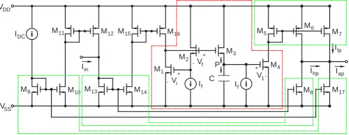
In Figure 1 MOSFETs M1-M2-M3-M4 along with a capacitor C constitute the basic
first-order low-pass core. The transfer function of this circuit can be determined as fol-lows. For the translinear loop comprised of M1-M2-M3-M4, we have the following
equa-tion for the close loop containing of VGS of the four-MOSFETs.
3 1
i f GS
V+V =V +V (1)
If the MOS transistors are operated in weak inversion region they would have expo-nential relationship between drain current and gate source voltage [16] of the form
0e
GS T V nV
D d
I =I (2)
where Id0 is the zero bias current, n = 1.5 is the subthreshold slope coefficient and VT
= kT/q = 26 mV at room temperature is known as thermal voltage. Now Equation (2) can be rearranged as
0 ln D GS T d I V nV I =
(3)
Therefore Equation (1) can be written as
1
0 0 0 0
ln in ln f ln f ln out
T T T T
d d d d
I sCV I
I I
nV nV nV nV
I I I I
+
+ = +
(4)
Equation (4) can be simplified as
1
0 0 0 0
ln in * f ln f * out
d d d d
I sCV I
I I
I I I I
+
=
(5)
From Equation (5), we finally obtain
(
1)
* *
in f f out
I I = CV +I I (6)
The value of V can be obtained by differentiating Equation (2) and putting in Equ-ation (6), thereby leading to
(
)
* *
in f T f out
I I = sCnV +I I (7)
[image:3.595.199.552.547.684.2]Rearranging Equation (7), we get the transfer function of the circuit as
Figure 1. The proposed log-domain first-order multifunction filter. VDD -VSS IDC M1 M2 M3 M4 M5 M6 M7 M8
M9 M10
M11 M12
M13 M14
M15 M16
M17 Iin
Iap Ihp
Ilp
If C If
+ -Vi
+ -Vf
V1 +
(
)
(
)
(
f T)
out
in f T
I nCV
I
I = s+I nCV (8)
Equation (8) represents the transfer function of the first-order low-pass filter and can be expressed as:
( )
00 out in I H s I s ω ω = =
+ (9)
where ω0=If
(
nCVT)
is the cutoff frequency of the low-pass filter. Now the low-pass output is given bylp out
I =I (10)
whereas the other two current outputs namely, Ihp and Iap are obtained by
hp out in
I =I −I (11)
2
ap out in
I = I −I (12)
for which the required operations are carried out by the appropriate current mirrors and current repeaters as shown in Figure 1. The transistors M9-M10-M17, M13-M14-M8
and M5-M6-M7 are current steering circuits and the MOSFET pairs M11-M12 and
M15-M16 are simple current mirrors.
Thus, the transfer functions of the low-pass, high-pass and all-pass filters realized by the proposed circuit are given by
( )
( )
00lp lp
in
I s
H
I s s
ω ω
= =
+ (13)
( )
( )
0hp hp
in
I s s
H
I s s ω
= = −
+ (14)
( )
( )
00ap ap
in
I s s
H
I s s
ω ω − +
= =
+ (15)
From Equations (13)-(15), it turns out that the cutoff frequency (in case of low-pass and high-pass) and phase (in case of all-pass) can be electronically tuned by changing the value of If since 0
f
T I nCV
ω = .
3. SPICE Simulations
The proposed circuit was simulated in SPICE employing TSMC 0.35 μm Level 3 CMOS process parameters [17]. The selected parameters were VDD = −VSS = 0.5 V, C = 3 pF, If
= 70 nA, Io = 0.3 µA and Iin = 0.2 μA. The aspect ratios of the transistors were taken as
shown in Table 2. From SPICE simulation, it has been verified that the condition re-quired for weak inversion operation (of all the four MOSFETs M1-M2-M3-M4 of the
ba-sic low-pass core) i.e. VGS < VT is satisfied.
3526
Table 1. TSMC 0.35 μm Level 3 CMOS process parameters.
Parameters NMOS PMOS
L 1U 1U
W 6U 6U
TOX 7.9E−9 7.9E−9
NSUB 1E17 1E17
GAMMA 0.5827871 0.4083894
PHI 0.7 0.7
VTO 0.5445549 −0.7140674
DELTA 0 0
UO 436.256147 212.2319801
ETA 0 9.999762E−4
THETA 0.1749684 0.2020774
KP 2.055786E−4 6.733755E
VMAX 8.309444E4 1.181551E5
KAPPA 0.2574081 1.5
RSH 0.0559398 30.0712458
NFS 1E12 1E12
TPG 1 −1
XJ 3E−7 2E−7
LD 3.162278E−11 5.000001E−13
WD 7.04672E−8 1.249872E−7
CGDO 2.82E−10 3.09E−10
CGSO 2.82E−10 3.09E−10
CGBO 1E−10 1E−10
CJ 1E−3 1.419508E−3
PB 0.9758533 0.8152753
MJ 0.3448504 0.5
CJSW 3.777852E−10 4.813504E−10
MJSW 0.3508721 0.5
Table 2. Aspect ratios.
MOS Transistors W/L (μm)
M1-M7, M9-M17 6/1
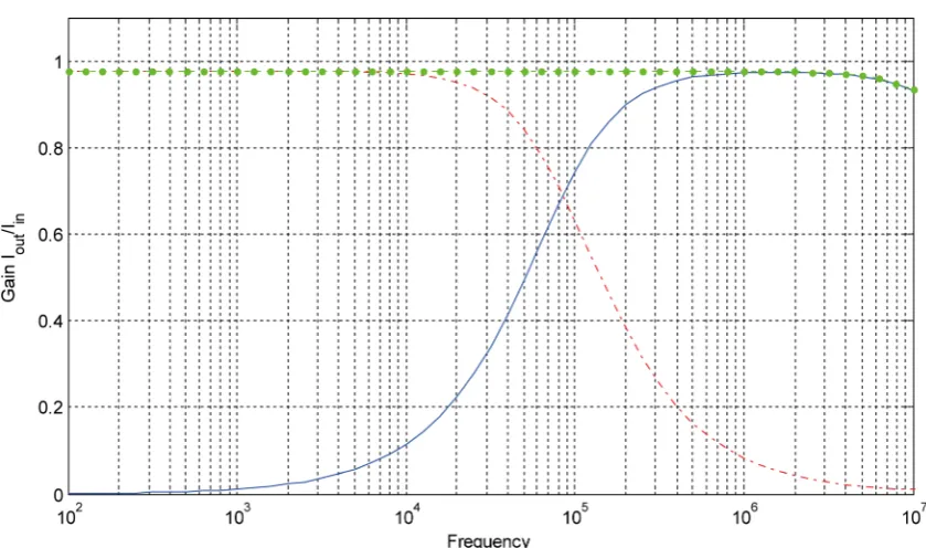
Figure 2. SPICE generated frequency response for the circuit of Figure 1 for If= 70 nA.
(a)
3528
[image:7.595.133.550.75.250.2](c)
Figure 3. Transient response of various circuits: (a) Transisent response of low-pass filter (f0 = 85 KHz); (b)
Tran-sient response of high-pass filter (f0 = 85 KHz); (c) Transient response of all-pass filter (f0 = 85 KHz).
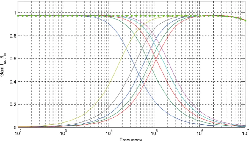
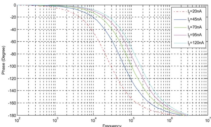
Figure 4. Electronically tuning characteristics observed by varying the current If(20 nA, 45 nA, 70 nA, 95 nA and
200 nA).
low-pass, high-pass and all-pass. Figures 3(a)-(c) shows the transient response of the low-pass, high-pass and all-pass filters designed for cutoff frequency of f0 = 85 KHz by
taking If = 70 nA. Figure 4 shows the electronic controllability of the cutoff frequency
by change of dc bias current (If = 20 nA, 45 nA, 70 nA, 95 nA and 120 nA) and Figure 5
[image:7.595.134.553.294.532.2]Figure 5. Phase response of the all-pass filter.
The SPICE simulation results, thus confirm the validity of the proposed filter.
4. Concluding Remarks
This paper presented a log-domain multifunction first-order filter using only MOSFETs and grounded capacitor. The circuit is capable of realizing all first-order filters namely, low-pass, high-pass and all-pass from the same configuration with electronic tunability of the radian frequency ω0. The circuit was simulated in SPICE employing TSMC 0.35
μm Level 3 CMOS process parameters. The SPICE simulation results have confirmed the workability and performance of the proposed MOS circuit. The proposed circuit which is operated from ±0.5 volt DC power supply and consumes only 2.62 μW power at If =120 nA, appears suitable for low voltage, low-power applications. This paper has
therefore, added a new CMOS multifunction first-order filter to the existing repertoire of log-domain filters (as in [1]-[9] [16] and references cited therein).
Acknowledgements
Authors are thankful to “Analog Signal Processing Research Lab”, Electronics Engi-neering Department, Institute of EngiEngi-neering and Technology, Lucknow for conduct-ing this research. The authors are also thankful to World Bank assisted project “Tech-nical Education Quality Improvement Program” for funding this lab.
References
[1] Adams, R.W. (1979) Filtering in the Log-Domain. 63rd AES Conference, New York, May 1979, 4.
[2] Frey, D.R. (1993) Log-Domain Filtering: An Approach to Current-Mode Filtering. IEE Proceedings G—Circuits, Devices and Systems, 140, 406-416.
3530
[3] Frey, D.R. (1996) Exponential State-Space Filters: A Generic Current-Mode Design Strate-gy. IEEE Transaction on CAS-I: Fundamental Theory and Applications, 43, 34-42.
http://dx.doi.org/10.1109/81.481459
[4] Tsividis, Y.P., Gopinathan, V. and Toth, L. (1990) Companding in Signal Processing. Elec-tronics Letters, 26, 1331-1332.http://dx.doi.org/10.1049/el:19900858
[5] Seevinck, E. (1990) Companding Current-Mode Integrator: A New Circuit Principle for Continuous-Time Monolithic Filters. Electronics Letters, 26, 2064-2065.
http://dx.doi.org/10.1049/el:19901319
[6] Toumazou, C., Ngarmnil, J. and Lande, T.S. (1994) Micropower Log-Domain Filter for Electronic Cochlea. Electronics Letters, 30, 1839-1841.
http://dx.doi.org/10.1049/el:19941284
[7] Jain, M.K., Singh, V.K. and Senani, R. (2015) A Bibliography of the Work Done on Exter-nally-Linear-Internally-Nonlinear Circuits during 1979-2014. American Journal of Electric-al and Electronic Engineering, 3, 64-71.
[8] Kircay, A. and Cam, U. (2006) Log-Domain First Order Multifunction Current-Mode Filter Design. IEEE 14th Signal Processing and Communications Applications, Antalya, 17-19 April 2006, 1-4.
[9] Kircay, A. and Cam, U. (2006) A Novel Log-Domain First Order Multifunction Filter. ETRI Journal, 28, 401-404.http://dx.doi.org/10.4218/etrij.06.0205.0117
[10] Arslanalp, R., Tola, A.T. and Yuce, E. (2011) Novel Resistorless First-order Current-Mode Universal Filter Employing a Grounded Capacitor. Radioengineering, 20, 656-664.
[11] Arslanalp, R., Tola, A.T. and Yuce, E. (2011) Fully Controllable First Order Current Mode Universal Filter Composed of BJT and a Grounded Capacitor. Electronics and Electrical Engineering, 6, 69-72.http://dx.doi.org/10.5755/j01.eee.112.6.448
[12] Kircay, A. (2014) Electronically Tunable-Current-Mode Square-Root-Domain First-Order Multifunction Filter. International Journal of Electronics, 101, 212-219.
http://dx.doi.org/10.1080/00207217.2013.778172
[13] Horng, J.W., Hou, C.L., Tseng, C.Y., Chang, R. and Yang, D.Y. (2012) Cascadable Cur-rent-Mode First-Order and Second-Order Multifunction Filters Employing Grounded Ca-pacitors. Active and Passive Electronic Components, 2012, Article ID: 261075.
http://dx.doi.org/10.1155/2012/261075
[14] Pal, R., Tiwari, R.C., Pandey, R. and Pandey, N. (2014) Single CDBA Based Current Mode First Order Multifunction Filter. International Journal of Engineering Science and Tech-nology (IJEST), 6, 444-451.
[15] Andreou, A.G., Boahen, K.A., Pouliquen, P.O., Pavasovic, A., Jenkins, R.E. and Strohbehn, K. (1991) Current-Mode Subthreshold MOS Circuits for Analog VLSI Neural Systems. IEEE Transactions on Neural Networks, 2, 205-213. http://dx.doi.org/10.1109/72.80331 [16] El-Marsy, E.I. and Wu, J. (1999) CMOS Micropower Universal Log-Domain Biquad. IEEE
Trans. CAS-I: Fundamental Theory and Applications, 1, 389-392.
Submit or recommend next manuscript to SCIRP and we will provide best service for you:
Accepting pre-submission inquiries through Email, Facebook, LinkedIn, Twitter, etc. A wide selection of journals (inclusive of 9 subjects, more than 200 journals)
Providing 24-hour high-quality service User-friendly online submission system Fair and swift peer-review system
Efficient typesetting and proofreading procedure
Display of the result of downloads and visits, as well as the number of cited articles Maximum dissemination of your research work