wM>\
WEM-l i WEM-l i i i i WEM-l WEM-l i «
mmaSÊHSÊÊí».
ifÄlM«
mmm
H H i
T*ffBi Svilir·*!'IS íww&Msiraiíím ^írnal^HJfií' ' ■ * íwríí! -(•".Iift.ti·,ΉΓΕ] • ' { ! ™ ι ΐ 1 g « l ·
LEGAL NOTICE
This document was prepared under the sponsorship of the Commission of the European Atomic Energy Community (EURATOM).
Neither the EURATOM Commission, its contractors nor any person acting on their behalf :
iiiliMll
1
:!
1° — Make any warranty or representation, express or implied, with respect to the accuracy, completeness, or usefulness of the information contained in this document, or that the use of any information, apparatus, method, or process disclosed in this document may not infringe privately owned rights; or
any liability with respect t o the use of, or for damages resulting from the use of any information, apparatus, method or
This report can be obtained, at the price of Belgian Francs 25,—, from: PRESSES ACADEMIQUES EUROPEENNES 98, Chaussée de Charleroi, Brussels 6.
Please remit payments:
— to BANQUE DE LA SOCIETE GENERALE (Agence Ma Campagne) - Brussels - account No 964.558,
— to BELGIAN AMERICAN BANK AND TRUST
¡ffiiiPWS^wiîfl
givin. state
COMPANY - New York - account No 121.86, to LLOYDS
London E.C.2,
Ufa' v^«i* «*- *. ^v.„ ^.-~~ =
— to LLOYDS BANK (Foreign) Ltd. 10 Moorgate
-giving the reference : detector".
Printed by E. Guyot, s. a. Brussels, October 1963.
E U R 4 2 9 . e
ALPHA RATEMETER W I T H SOLID STATE D ETECTOR by V. MANDL and L. OLIVEIRA.
European Atomic Energy Community - EURATOM Joint Nuclear Research Center
ïspra Establishment (Italy) Nuclear Chemistry Service
Brussels, October 1963 - pages 11 - figures 3.
EUR 4 2 9 . e
EUROPEAN ATOMIC ENERGY COMMUNITY - EURATOM
ALPHA RATEMETER WITH SOLID STATE
DETECTOR
by
V. MANDL and L. OLIVEIRA
1963
Joint Nuclear Research Center Ispra Establishment - Italy
CONTENTS
1 — Introduction 5
2 — The description of the circuit 5
3 — Performances 6
4 — Acknowledgments 6
KEY TO THE FIGURES
Fig. 1 — The schematic of the monitor. All resistances are in ohms, 1/4 W, i 10 %
and all capacitors in microfarad unless otherwise specified 7
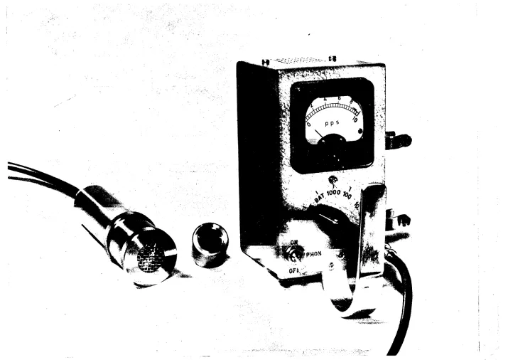
Fig. 2 — The solid state detector alpha ratemeter 9
Fig. 3 — The schematic of the external power supply. All resistances are in ohms,
ALPHA RATEMETER WITH SOLID STATE DETECTOR
by
V. MANDL and L. OLIVEIRA *
SUMMARY
A portable alpha monitor with solid state detectors is described. The full scale range is of 1000 p.p.s. and an auditive indication is also provided. The battery life is about 70 hours. The instrument operates correctly in a gamma field up to 8 r/h.
1 — I N T R O D U C T I O N
A portable alpha monitor with surface barrier solid state detectors (L) developed in our
laboratory, has been built.
The main advantages of these detectors are their small size, light weight, and the possi-bility to operate them with the same voltage supply used for the electronic circuit. The absence of a high voltage makes the instrument much simpler and more reliable.
The instrument normally uses a single solid state detector of 2 cm2 sensitive area. These
small dimensions are particularly useful to determine located alpha contaminations. If required more detectors can be connected in parallel to increase the sensitive area.
The detector is placed in a probe connected to the monitor by a coaxial cable. This allows the remote operation.
2 — T H E D E S C R I P T I O N OF T H E CIRCUIT
The circuit diagram of the monitor is shown in Fig. 1. The instrument consists of : a charge sensitive preamplifier, a main amplifier, an audio circuit and the diode pump.
The detector signals are amplified by the charge sensitive preamplifier (Tu T2 and T3)
placed inside the probe and supplied through the coaxial connecting cable. This charge sensitive configuration has a dynamic input capacitance of 2 500 pF approximately ; it makes possible the interchanging of the detectors and the use of a mosaic type head.
* Qualified trainee- Present address : Instituto de Pesquisas Radioativas, Belo Horizonte, Brasil.
í1) F. Cappellani, G. Restelli. Construction and Performances of Silicon Surface Barrier Detectors. To be
The main amplifier has two shaping constants of 2 μβεα The differentiation is placed in the input circuit of the transistor T4 and the integration network between transistors T5 and T„.
The signaltonoise ratio with an equivalent alpha particle of 1 Mev. an external input capa citance of 800 pF, and a reverse current of 1 μΑ is about 5. Such a low energy has been considered because of the attenuation which the particles undergo through the air and the sheet of aluminium which keeps the detector light protected.
The pulse shaper (transistors T7, Ts, T9) drives the audio and measuring circuit (T10,
Tn) . The diode pump supplies a 50 μΑ meter. The full scale ranges are : 10, 100 and 1000 p.p.s.
with the time constant of 5, 2 and 1 sec. respectively.
The overall resolving time is of 50 /¿sec. The detector and the charge sensitive preampli fier are placed inside a stainless steel probe in order to be easily decontaminated, if required. The detector is shock protected with a metallic mesh. A simple disconnecting system is foreseen providing an easy change of detectors. The complete instrument is shown in Fig. 2.
3 — PERFORMANCES
The instrument operates correctly up to 40° C.
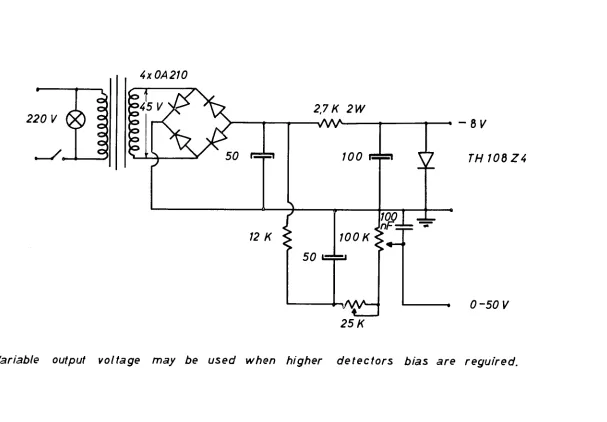
The power is normally supplied from two series connected mercurycell batteries assuring a rather constant voltage for about 70 hours service. In fixed operation an external power supply may be also used. (Fig. 3)
The solid state detectors are, as well known, almost insensible to gammas. Our monitor has been checked in a gamma field up to 8 r/h of Co60 and only a higher noise has been observed
in the output of the charge sensitive preamplifier but no pulses were counted. At higher field levels however the noise is of the same order of magnitude as 5,8 Mev alphas.
4 — ACKNOWLEDGMENTS
We wish to thank Dr Bertolini for many useful discussions, Messrs. Cappellani and Restelli
Τ, = Τ2 = 7^ = 2 Ν 2049
-7V
33Μ .
SOLID STATE DETECTOR^. 47n F
H H
-27K
WK
>4,7K
IM .
Tl 5pF
'33 Κ
)Τ2 Î S « I
J
HJso ~T7c
75«
390
¿ W v t
7^ = T5 = 2N 274
390
Tg = OC 719
250 \W nF
s/\A/· * τ -7,6 V
lnF
250
- Λ Λ Λ ^ - ^ - C
6δ
T7 = Tå = Τ9 = 2Ν 404 Τ!0 = OC 80 7; ; = 2Λ/404
Β - β f
PHONO l /o w
up
/SA 8,2 Λ· < J J / f ?3,9Κ2 2 nF
û
47nF33 nF
<2:2K
ho
/ \ c \ .
>4?K
>3,9K \27K
Ί2Κ
rO"
25 η F 22K<
Hh
660 nFD3 0A9 3.3 nF
HH
rìH
6änF 330 pF 6finF750/Q
5 1 2 WO
200 WK' 'JOK
10K SOO
HH
e*
w.,
.2^4W L·^.
L-Cf)
JJ
2l J, < :¡
I 0 < ¡ 0 / 1 9 .2
Ζ
0A9 D2 1 2-r
ι
!
3 4 5
500
. J
f
■D
t -OFF. 2 -CHECK BAT
3 7000 P P S . 4 - WO PPS, 5-10 PPS.
* EXTERNAL POWER SUPPLY
[image:11.842.52.803.34.518.2]220 V
( g )
4x0/42/0
2,7K 2W
- V W
700
f Y
12 K
50
JOOK
100
_ L
VW—l
25/<
- 8 1 /
TH 10ÕZ4
-* 0 -50 1/
[image:15.842.183.790.63.485.2]Variable output voltage may be used when higher detectors bias are reguired.
Fig. 3 — The schematic of the external power supply. All resistances are in ohms,