Abstract—This paper Proposed an intelligent current control
topology for grid-connected operations of distributed generation (DG), which supports the DG to transfer a sinusoidal current into the utility grid despite the distorted grid voltage and non-linear local load conditions. The proposed current controller is designed in the synchronous reference frame and composed of a fuzzy controller. Hence, the control strategy can be greatly simplified efficiently. In addition, the proposed control method does not require the local load current measurement or harmonic analysis of the grid voltage. Therefore, the proposed control method can be easily adopted into the traditional DG control system without installation of extra hardware. Despite the reduced number of sensors, the grid current quality is significantly improved. The operation principle of the proposed control method is analyzed in detail, and its effectiveness is validated through observing total harmonic distortion (THD) and simulated results. Index Terms—Distributed generation (DG), Fuzzy controller grid-connected inverter, harmonic compensation, nonlinear load, repetitive control.
I. INTRODUCTION
D
istribution generation units popularly Renewable energy sources, such as wind turbines, photovoltaic, and fuel cells, has greatly increased in recent decades to address concerns about the global energy crisis, depletion of fossil fuels, and environmental pollution problems. Grid Current Compensator for Grid-Connected Distributed Generation under linear and non linear load condition are analyzed with PI-RC controller in [1] and the operational observations show the efficiency of the controller bitterly. As a result, a large number of renewable energy sources have been integrated in power distribution systems in the form of distributed generation (DG) [2]. DG systems can offer many advantages over traditional power generation, such as small size, low cost, high efficiency, and clean electric power generation. A DG system is typically operated in a grid-connected mode where themaximum available power is extracted from energy sources and transferred to the utility grid [3]-[9]. In addition, to exploit full advantages of a DG system, the DG can be also equipped and operated with local loads, where the DG supplies power to the local load and transfers surplus power to the grid [10]-[15]. In both configurations, i.e., with and without the local load, the prime objective of the DG system is to transfer a high-quality current (grid current) into the utility grid with the limited total harmonic distortion (THD) of the grid current at 5%, as recommended in the IEEE 1547 standards [16].
To produce a high-quality grid current, various current control strategies have been introduced, such as hysteresis, predictive, integral (PI), and proportional-resonant (PR) controllers. Hysteresis control is simple and offers rapid responses; however, it regularly produces high and variable switching frequencies, which results in high current ripples and difficulties in the output filter design [4]. Meanwhile, predictive control is a viable solution for current regulation of the grid-connected DG. However, despite its rapid response, the control performance of the predictive controller strongly relies on system parameters [5]. Therefore, system uncertainty is an important issue affecting the grid current quality. The PI controller in the synchronously rotating (d-q) reference frame and the PR controller in the stationary (α-β) reference frame are effective solutions that are commonly adopted to achieve a high-quality grid current [3], [4], [11], [12]. However, these current controllers are only effective when the grid voltage is ideally balanced and sinusoidal. Unfortunately, due to the popular use of nonlinear loads such as diode rectifiers and adjustable-speed ac motor drives in power systems, the grid voltage at the point of common coupling (PCC) is typically not pure sinusoidal, but instead can be unbalanced or distorted. These abnormal grid voltage conditions can strongly deteriorate the performance of the regulating grid current.
To eliminate the adverse effect of the distorted grid voltage on the grid current quality, several harmonic compensation methods have been introduced [7]-[9]. A novel compensation approach for reducing the THD of the grid current under distorted grid voltage is introduced. In this method, the harmonic components in the grid voltage are extracted, and the Cauchy-Schwarz inequality theory is adopted to find the minimum point of the grid current THD. The grid current quality therefore relies heavily on the accuracy of the grid voltage harmonic analysis; if the harmonic components in the
Kasi Gautami satya1, D. Revathi2
PG Student, Department of EEE, KIET, Kakinada, India.1 Asst. Professor, Department of EEE, KIET, Kakinada, India.2
An Improved Grid Current Compensator for
Grid-Connected Distributed Generation under
grid voltage are varied, it is difficult to maintain a good grid current quality. Moreover, the searching algorithm requires a large calculation time and can operate only offline. Several selective harmonic compensators are developed using a resonant controller, in which the resonant controller tuned at the sixth multiple of the fundamental frequency is added to eliminate the effect of fifth and seventh harmonic grid voltages on the grid current quality. The grid current quality can be improved, due to the additional resonant controllers. However, if higher order harmonics are taken into account, more resonant controllers should be added because a single resonant controller can regulate only one specific harmonic component [8], [9]. Unfortunately, adding more controllers increases the complexity of the control system. To improve the grid current quality with a simplified control scheme, the repetitive control technique has been adopted [13]. A repetitive controller (RC) serves as a bank of resonant controllers to compensate a large number of harmonic components with a simple delay structure. However, despite the effectiveness of the RC in harmonic compensation, the traditional RC has a long delay time, which regularly limits the dynamic response of the current controller. For example, as reported in [13], the dynamic response of the grid current under a step change of the current reference is approximately 150 ms, which is extremely slow compared with other control methods. In addition, even with the utilization of the RC, this method is unable to bring the THD of the grid current lower than the limited value 5% in the IEEE 1547 standards. Along with grid voltage distortion, the presence of nonlinear loads in the local load of the DG also causes a negative impact on the grid current quality [14]. To address this problem, the local load current measurement and a load current feedforward loop are regularly adopted [14], [15]. Although these compensation methods are effective in improving grid current quality, the requirement of additional hardware, specifically the current sensor for measuring the local load current, is the main drawback of this control method. Furthermore, most aforementioned studies consider and separately tackle the impact of distorted grid voltage or the nonlinear local load; none of them simultaneously takes into account those issues. To overcome the limitations of aforementioned studies, this paper proposes an advanced current control strategy for the grid-connected DG, which makes the grid current sinusoidal by simultaneously eliminating the effect of nonlinear local load and grid voltage distortions. First, the influence of the grid designed in the d-q reference frame and is composed of a Fuzzy controller.
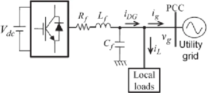
Fig. 1. System configuration of a grid-connected DG system with local load.
One single RC can compensate a large number of harmonic components with a simple delay function. Hence, the control strategy can be greatly simplified. Another advantage of the proposed control method is that it does not demand the local load current measurement and the harmonic analysis of the grid voltage. Therefore, the proposed control method can be easily adopted into the traditional DG control system without the installation of extra hardware. Despite the reduced number of sensors, the performance of the proposed grid current controller with fuzzy technique is significantly improved compared with that of the PI current controller. In addition, with the combination of fuzzy, the dynamic response of the proposed current controller is also greatly enhanced compared with that of the traditional PI-RC. The feasibility of the proposed control strategy is completely verified by simulation results.
II. SYSTEM CONFIGURATION AND ANALYSIS OF GRID VOLTAGE DISTORTION AND NONLINEAR
LOCAL LOAD
Fig. 1 shows the system configuration of a three-phase DG operating in grid-connected mode. The system consists of a dc power source, a voltage-source inverter (VSI), an output LC filter, local loads, and the utility grid. The purpose of the DG system is to supply power to its local load and to transfer surplus power to the utility grid at the PCC. To guarantee high-quality power, the current that the DG transfers to grid (ig ) should be balanced, sinusoidal, and have a low THD value. However, because of the distorted grid voltage and nonlinear local loads that typically exist in the power system, it is not easy to satisfy these requirements.
A. Effect of Grid Voltage Distortion
To assess the impact of grid voltage distortion on the grid current performance of the DG, a model of the grid-connected DG system is developed, as shown in Fig. 2. In this model, the VSI of the DG is simplified as voltage source (vi ). The inverter transfers a grid current (ig ) to the utility grid (vg ). For simplification purpose, it is assumed that the local load is not connected into the system. In Fig. 2(a), the voltage equation of the system is given as
(1) whereRf andLf are the equivalent resistance and inductance of the inductorLf, respectively.
Fig. 2. Model of grid-connected DG system under distorted grid voltage condition.
(a) General condition;
(b) at the fundamental frequency; and (c) at harmonic frequencies.
If both the inverter voltage and the grid voltage are composed of the fundamental and harmonic components as (2), the voltage equation of (1) can be decomposed into (3) and (4), and the system model shown in Fig. 2(a) can be expressed as Fig. 2(b) and (c), respectively. That is
B. Effect of Nonlinear Local Load
Fig. 3 shows the model of a grid-connected DG system with a local load, whereby the local load is represented as a current source iL, and the DG is represented as a controlled current source iDG. According to Fig. 3, the relationship of DG current iDG, load current iL, and grid current ig is described as
Fig. 3. Model of grid-connected DG system with nonlinear local load.
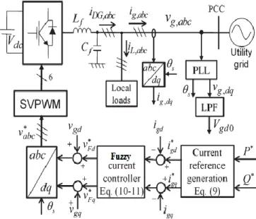
Fig. 4. Overall block diagram of the proposed control strategy. Assuming that the local load is nonlinear, e.g., a three-phase diode rectifier, the load current is composed of the fundamental and harmonic components as
where iL1 and iLh are the fundamental and harmonic compo- nents of the load current, respectively.
Substituting (6) into (5), we have
From (7), it is obvious that, in order to transfer sinusoidal grid current ig into the grid, DG current iDG should include the
harmonic components that can compensate the load current harmonics Therefore, it is important to design an effective and low-cost current controller that can generate the specific harmonic components to compensate the load current harmonics. Generally, traditional current controllers, such as the PI or PR controllers, cannot realize this demand because they lack the capability to regulate harmonic components.
III. PROPOSED CONTROL SCHEME
To enhance grid current quality, an advanced current control strategy, as shown in Fig. 4, is introduced. Although there are several approaches to avoid the grid voltage sensors and a phase-locked loop (PLL) [19], Fig. 4 contains the grid voltage sensor and a PLL for simple and effective implementing of the proposed algorithm, which is developed in the d-q reference frame.
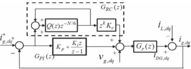
Fig. 5. Block diagram of the current controller.
The proposed control scheme is composed of three main parts: the PLL, the current reference generation scheme, and the current controller. The operation of the PLL under distorted grid voltage has been investigated, in detail, in [20]; therefore, it will not be addressed in this paper. As shown in Fig. 4, the control Fig. 6. Bode diagram of the proposed PI-RC current controller. strategy operates without the local load current measurement and harmonic voltage analysis on the grid voltage. Therefore, it can be developed without requiring additional hardware. Moreover, it can simultaneously address the effect of nonlinear local load and distorted grid voltage on the grid current quality .
A. Current Reference Generation
As shown in Fig. 4, the current references for the current controller can be generated in the d-q reference frame based on the desired power and grid voltage as follows [15]:
where P ∗ and Q∗ are the reference active and reactive power, respectively; vgd represents the instantaneous grid voltage in the d-q frame; and igd and igq denote the direct and quadrature components of the grid current, respectively.Under ideal conditions, the magnitude of vgd has a constant value in the d-q reference frame because the grid voltage is pure sinusoidal. However, if the grid voltage is distorted, the magnitude of vgd no longer can be a constant value. As a consequence, reference current igd and igq cannot be constant in (8). To overcome this problem, a low-pass filter (LPF) is used to obtain the average value of vgd , and the d-q reference currents are modified as follows, whereVgd0 is the average value of vgd, which is obtained through the LPF in Fig. 4
IV. Fuzzy controller
The word Fuzzy means vagueness. Fuzziness occurs when the boundary of piece of information is not clear-cut. In 1965 Lotfi A. Zahed propounded the fuzzy set theory. Fuzzy set theory exhibits immense potential for effective solving of the uncertainty in the
problem. Fuzzy set theory is an excellent mathematical tool to handle the uncertainty arising due to vagueness. Understanding human speech and recognizing handwritten characters are some common instances where fuzziness manifests.
Fuzzy set theory is an extension of classical set theory where elements have varying degrees of membership. Fuzzy logic uses the whole interval between 0 and 1 to describe human reasoning. In FLC the input variables are mapped by sets of membership functions and these are called as “FUZZY SETS”.
Fuzzy set comprises from a membership function which could be defines by parameters. The value between 0 and 1 reveals a degree of membership to the fuzzy set. The process of converting the crisp input to a fuzzy value is called as “fuzzificaton.” The output of the Fuzzier module is interfaced with the rules. The basic operation of FLC is constructed from fuzzy control rules utilizing the values of fuzzy sets in general for the error and the change of error and control action. Basic fuzzy module is shown in fig.6.
The results are combined to give a crisp output controlling the output variable and this process is called as “DEFUZZIFICATION.”
Fig.6. Fuzzy Basic Module
i. Fuzzy rules
In the fuzzy control, input and output variables are the size of the form to describe in words, so to select special vocabulary to describe these variables, generally used in "big, medium and small" Three words to express the controller input and output variables state, plus the positive and negative directions, and zero, a total of seven words : { negative big, negative medium, negative small, zero, positive small, middle, CT } , the general terms used in the English abbreviation prefix : {NB , NM, NS , ZE, PS , PM, PB}.
COE
E
NB NM NS
ZE
PS PM PB
NB
NB NB NB NB NM NS ZE
NM
NB NB NB NM NS
ZE
PS
NS
NB NM NS NS
ZE
PS PM
ZE
NB NM NS
ZE
PB
NS ZE
PS
NM NS
ZE
PS
PM PM PB
PM
NS
ZE
PS PM
PB
PB PB
PB
ZE
PS
PM PB
PB
PB PB
ii. Membership Functions
A membership function (MF) is a curve that defines how each point in the input space is mapped to a membership value (or degree of membership) between 0 and 1. A membership function for a fuzzy set A on the universe of discourse X is defined as µA: X → [0,1], where each element of X is mapped to a value between 0 and 1. This value, called membership value or degree of membership, quantifies the grade of membership of the element in X to the fuzzy set A. Membership functions allow us to graphically represent a fuzzy set. The x axis represents the universe of discourse, whereas the y axis represents the degrees of membership in the [0,1] interval. Simple functions are used to build membership functions. Because we are defining fuzzy concepts, using more complex functions does not add more precision. Below is a list of the membership functions we will use in the practical section of this tutorial. Triangular function: defined by a lower limit a, an upper limit b, and a value m, where a < m < b.
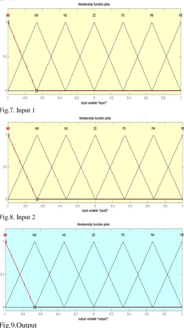
Fig.7. Input 1
Fig.8. Input 2
Fig.9.Output
Membership functions plots, Fig.7, Fig.8, Fig 9 are the input 1, input2 and output of fuzzy controller respectively. These plots are obtained according to the rules written in the fuzzy tool box and the switching process depends upon these rules.
TABLE I
SYSTEM PARAMETERS
V. SIMULATION RESULTS
A simulation model of the DG system is built by MATLAB/Simulink software to verify the effectiveness of the proposed control method. The system parameters are given in Table I. In the simulation, three cases are taken into account. 1) Case I: The grid voltage is sinusoidal and the linear local load is used.
2) Case II: The grid voltage is sinusoidal and the nonlinear local load is used.
3) Case III: The grid voltage is distorted and the nonlinear local load is used.
In Cases I and II, the grid voltage is assumed as a pure sinusoidal waveform. In Case III, the distorted grid voltage is supplied with the harmonic components: 3.5% 5th harmonic, 3% 7th harmonic, 1% 11th harmonic, and 1% 13th harmonic. The THD of grid voltage is about 4.82%. This grid voltage condition complies with the IEEE 519-1992 harmonic restriction standards, where the THD of grid voltage is less than 5% . In all test cases, the reference grid current is set at igd = 10 A and igq = 0, and the fuzzy current controller is investigated to compare its control performances.
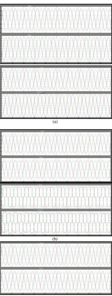
Fig. 10 depicts the steady-state performance of the grid-connected DG by using the Fuzzy current controller, in which the waveforms of grid voltage (vg,abc ), grid current (ig,abc ),
local load current (iL,abc ), and DG current (iDG,abc ) are
plotted. As shown in Fig. 10, the Fuzzy controller is able to offer a good performance in Case I, when the grid voltage is ideal sinusoidal and the local load is linear. In the other circumstances, due to the effect of distorted grid voltage and the nonlinear local load, the fuzzy current controller is somewhat unable to transfer a sinusoidal grid current to the utility grid. In fact, because of the popular use of nonlinear loads in the DG local load and distribution system, the ideal sinusoidal condition of the grid voltage is very rare. On the other hand, the conditions, as given in Cases II and III, frequently occur in practice. As a result, the conventional PI controller is sufficient to some extent to offer a good quality of the grid current.
(a)
(b)
(c)
Fig. 10. Simulation results with the PI current controller: (a) Case I; (b) Case II; and (c) Case III.
TABLE II
SUMMARY OF THD VALUES OF GRID CURRENT WITH PI AND PROPOSED CURRENT CONTROLLERS
PI & RC current controller FUZZY LOGIC current controller Case I Case II Case III Case I Case II Case III THD Of ig 1.55% 1.80% 1.92% 1.23% 1.61% 1.76% VI. CONCLUSION
This paper has proposed an intelligent current control strategy for the grid-connected DG to simultaneously eliminate the effect of grid voltage distortion and nonlinear local load on the grid current. The simulation results established that the DG with the proposed current controller can sufficiently transfer a sinusoidal current to the utility grid, despite the nonlinear local load and distorted grid voltage conditions. The proposed current control scheme can be implemented without the local load current sensor and harmonic analysis of the grid voltage; therefore, it can be easily integrated in the conventional control scheme without installation of extra hardware. Despite the reduced number of current sensors, the quality of the grid current is significantly improved: the THD value of the grid current is decreased considerably compared with that achieved by using the conventional current controller like PI. In addition, the proposed current controller also maintained a good quality of grid current under grid frequency variations and total harmonic distortion (THD) decreases. Moreover, the dynamic response of the grid current controller was also greatly enhanced compared with that of the traditional PI-RC topology.
REFERENCES
[1] Quoc-Nam Trinh, Hong-Hee Lee, “An Enhanced Grid Current Compensator for Grid-Connected Distributed Generation Under Nonlinear Loads and Grid Voltage Distortions,” IEEE TRANS.Ind.Electronics, vol. 61, no. 12, pp. 6528-6537, Dec. 2014.
[2] R. C. Dugan and T. E. McDermott, “Distributed generation,” IEEE Ind.Appl. Mag., vol. 8, no. 2, pp. 19-25, Mar./Apr. 2002.
[3] F. Blaabjerg, R. Teodorescu, M. Liserre, and A. V. Timbus, “Overviewof control and grid synchronization for distributed power generation systems,” IEEE Trans. Ind. Electron., vol. 53, no. 5, pp. 1398-1409,Oct. 2006.
[4] J. A. Suul, K. Ljokelsoy, T. Midtsund, and T. Undeland, “Synchronous reference frame hysteresis current control for grid converter applications,” IEEE Trans. Ind. Appl., vol. 47, no. 5, pp. 2183-2194, Sep./Oct. 2011.
[5] Q. Zeng and L. Chang, “An advanced SVPWM-based predictive current controller for three-phase inverters in distributed generation systems,” IEEE Trans. Ind. Electron., vol. 55, no. 3, pp. 1235-1246, Mar. 2008.
[6] S. Buso and P. Mattavelli, “Digital control in power electronics,” in Syn thesis Lectures on Power Electronics. San Rafael, CA, USA: Morgan & Claypool, 2006.
[7] C. A. Busada, S. Gomez Jorge, A. E. Leon, and J. A. Solsona, “Current controller based on reduced order generalized integrators for distributed generation systems,” IEEE Trans. Ind. Electron., vol. 59, no. 7, pp. 2898- 2909, Jul. 2012.
[8] M. Liserre, R. Teodorescu, and F. Blaabjerg, “Multiple harmonics control for three-phase grid converter systems with the use of PI-RES current controller in a rotating frame,” IEEE Trans. Power Electron., vol. 21, no. 3, pp. 836-841, May 2006.
[9] M. Castilla, J. Miret, A. Camacho, J. Matas, and L. G. de Vicuna, “Reduction of current harmonic distortion in three-phase grid-connected photo voltaic inverters via resonant current control,” IEEE Trans. Ind. Electron., vol. 60, no. 4, pp. 1464-1472, Apr. 2013.
[10] R.-J. Wai, C.-Y. Lin, Y.-C. Huang, and Y.-R. Chang, “Design of high-performance stand-alone and grid-connected inverter for distributed generation applications,” IEEE Trans. Ind. Electron., vol. 60, no. 4,pp. 1542-1555, Apr. 2013.
[11] I. J. Balaguer, Q. Lei, S. Yang, U. Supatti, and F. Z. Peng, “Control for grid-connected and intentional islanding operations of distributed power generation,” IEEE Trans. Ind. Electron., vol. 58, no. 1, pp. 147-157,Jan. 2011.
[12] G. G. Pozzebon, A. F. Q. Goncalves, G. G. Pena, N. E. M. Mocambique, and R. Q. Machado, “Operation of a three-phase power converter connected to a distribution system,” IEEE Trans. Ind. Electron., vol. 60, no. 5, pp. 1810-1818, May 2013.
[13] Q.-C. Zhong and T. Hornik, “Cascaded current-voltage control to improve the power quality for a grid-connected inverter with a local load,” IEEE Trans. Ind. Electron., vol. 60, no. 4, pp. 1344-1355, Apr. 2013.
[14] Z. Yao and L. Xiao, “Control of single-phase grid-connected inverterswith nonlinear loads,” IEEE Trans. Ind. Electron., vol. 60, no. 4, pp. 1384-1389, Apr. 2013.
[15] Z. Liu, J. Liu, and Y. Zhao, “A unified control strategy for three-phase inverter in distributed generation,” IEEE Trans. Power Electron., vol. 29,no. 3, pp. 1176-1191, Mar. 2014.
[16] IEEE Application Guide for IEEE Std 1547, IEEE Standard for Interconnecting Distributed Resources with Electric Power Systems, IEEE Std.1547.2-2008, 2008.