Abstract— The electrical power system is a dynamic system which is no longer operated as isolated system, but as interconnected system which includes thousands of electrical elements spread over a wide area. [P.Kundru, 1994]
Power system stability is one of the most crucial issues which deals with the response of the system to the errors such as sudden load change, short circuit, prime mover failure, excitation failure etc. In all these conditions to maintain the stability or to improve the transient stability and the damping oscillation of power system, in the n/w. Recently, Flexible Alternative Current Transmission System(FACTS) controllers have been proposed to enhance the transient or dynamic stability of the power systems.
In this paper a fuzzy logic controller is proposed to apply a suitable control signal to STATCOM to improve the fault clearing time and transient stability improvement within a particular duration. The controller designed using fuzzy logic implements human reasoning that can be programmed into fuzzy logic language (membership functions, rules and the rule interpretation). Here fuzzy logic is a methodology, algorithm for optimized implementation of controlled signal to the real system. Proposed method is implemented in a single machine infinite bus system and the results are compared with conventional energy function based controllers.
INTRODUCTION
The nonlinear fuzzy controller is proposed to supply a supplementary control signal to STATCOM to increase the critical clearing time and overcome the uncertainties existing in the power systems. The Proposed method is implemented in a single machine infinite bus system and the results are compared with conventional energy function-based controllers. . Fuzzy logic provides powerful tools to consider these uncertainties and their modelling. To enhance the transient stability of synchronous generator a combination of fuzzy logic controller and STATCOM are employed at generator end. Here the observations clarified that the transient stability on generator terminal was due to LLL-G faults. The main concern is about the positive sequence voltage and active power deviation with and without fault in interconnected power system. The variation in positive sequence voltage and active power is due to LLL-G Fault with respect to time with fuzzy logic based STATCOM (FLSTATCOM) controller.The active and reactive power transfer between the power system and the STATCOM is caused by the voltage difference across this reactance.
As opposed by the modern control theory, fuzzy logic design is not based on the mathematical model of the process. The controller designed using fuzzy logic implements human reasoning that can be programmed into fuzzy logic language (i.e. membership functions and rule). MATHEMATICAL
MODELLING:->> Modelling of the
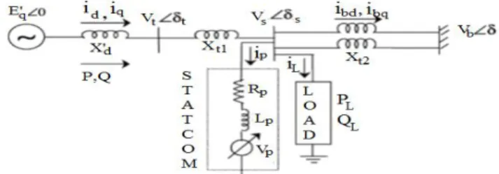
STATCOM:-The fundamental principle of STATCOM is the generation of a controllable ac voltage source by a VSI connected to a dc capacitor. The ac voltage source appears behind a transformer leakage reactance. The active and reactive power transfer is caused by the voltage difference across this reactance. The ac voltage control is achieved by firing angle control. There are two control objectives in STATCOM control, i.e. ac-bus voltage control and dc voltage control across the capacitor. There are 2 voltage regulators designed for this purpose: ac bus voltage regulators and dc voltage regulator. The modelling and control design are usually carried in the standard synchronous d–q frame.The synchronous generator is described by a third-order nonlinear mathematical model
i.e-Fig: 1.1Single machine infinite bus power system with a STATCOM. ………..….………. (1.01)
……... (1.02) …….…. (1.03)
Where; and
The dynamic equations governing the instantaneous values of the three-phase voltage across the current flowing into it,
………... (1.04)
Where, ….……..……… (1.05)
…………..……. (1.07) ………. (1.08)
Transient stability improvement by using
STATCOM based on Fuzzy Logic
Prabha Pandit
Rohit Kumar
Manju Gupta
Department of Elec and Elex Engg. Department of Elec and Elex Engg Department of Elec and Elex Engg OIST(Bhopal) U.I.T, RGPV (Bhopal) OIST(Bhopal
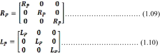
………..……… (1.09) ……….…………..……… (1.10) Under the assumption that the system has no zero sequence components, all currents and voltages can be uniquely represented by equivalent space phasors and then transformed into the synchronous d-q-oframe by applying the following park’s Transformation.
….. (1.11) Where, θ = angle between d-axis and reference phase axis. Thus, transformed dynamic equations are
………. (1.12) .………. (1.13) It is to be noted that in the d-axis and q-axis components of the VSI voltage. i.e. Vpdand Vpq,all harmonics, which are near to/above the VSI switching frequency, are neglected. In the real-time implementation of these quantities, they should be converted into modulation index (m) and phase angle (φ):
and …… (1.14)
For an effective dc-voltage control, the input power should be equal to the sum of load power (if any) and the charging rate o capacitor voltage on an instantaneous basis.Thus, by power balance between the ac input and the dc output,
…….... (1.15) ………...… (1.16)
Hence, …….(1.17)
Equation (1.17) models the dynamic behavior of the dc-side capacitor voltage. In equations (1.12), (1.13) and (1.16) together describe the dynamic model of the STATCOM and is summarized below for readiness in equation (1.18).
+ ……… (1.18)
IMLIMENTATION AND
RESULTS:-The simulation results employing MATLAB / SIMULINK for both types of STATCOM Controller i.e., conventional and fuzzy logic based STATCOM.
Load/STATCOM Load Power Bus Location
1stLoad 500MW 3
STATCOM 100MVA,13.8KV, 200MVAR
2
The performance of the proposed model is tested on
two-machines three-bus systems as shown in figure (8.1).The modelling of a simple 500 KV transmission system
containing with two hydraulic power plants (or, Salient pole generator)and Fuzzy Logic based STATCOM Controller are connected at mid-point of transmission line to improve transient stability and power system oscillations damping. The fuzzy logic controller makes system as self-correcting and take the decision like human. The fuzzy based
STATCOM enhance the transient automatically within time period with safe operation. Despite the simple structure of the illustrated power system in the figure, the phasor simulation method can be used to simulate more complex power grids.
G1 and G2: Generator. B1, B2 and B3; bus no.
Figure 1.2 Single Line diagram of 2-Machine 3-Bus system of Power System Model with STATCOM Controller.
Parameters in table
Table 1.3: Generator and Transformer Ratings Generator/
Transformer PowerGeneration Voltage & FrequencyRatings
G1 1000MVA 16.5KV,50Hz
G2 500MVA 18KV,50Hz
T1 1000MVA 13.8KV/500KV,50Hz
T2 500MVA 13.8KV/500KV,
500Hz
1.4: Loads and STATCOM Ratings at Bus locations A 1000 MVA hydraulic generation plant (G1) is connected to a load centre through a long 500 KV, 700 km transmission line. A 5000 MW of resistive load is modelled as the load centre. The remote 1000 MVA plant and a local generation of 5000 MVA (G2) feed the load. A load flow has been performed on this system with plant G1 generating 950 MW so that plant G2 produces 4046 MW. The line carries 944 MW which is close to its surge impedance loading (SIL = 977 MW). To maintain system stability after faults, the transmission line is shunt compensated at its canter by a 200 MVAr, STATCOM. The STATCOM has a power oscillation damping (POD) unit as well as fuzzy logic controller. The two machines are equipped with a Hydraulic Turbine and Governor(HTG), excitation system, and STATCOM with Fuzzy Logic Controller.
The other three-phase elements such as the inductive voltage source, the Y grounded/Delta transformer, and the loads are standard blocks from the Electrical Source and Elements libraries of power. If you open the dialog box of the Three-Phase Fault and Three-Phase Breaker blocks, you see how the switching times are specified. The Machine Measurement Demux block provided in the Machines library
is used to Demux the output signals of the Synchronous Machines and Asynchronous Machines. The Synchronous Machine voltage and active power (MW) outputs are used as feedback inputs to a Simulink control system that contains the prime mover and governor block as well as an excitation block. The excitation system is the standard block provided in the Machines library. The Syn. Machine parameters as well as the prime mover and governor models were taken from references .The performance of the proposed system has been studied in a comparative manner. The comparison is performed without considering any STATCOM controller in the system, with conventional STATCOM, and with Fuzzy Logic based STATCOM Controller as well as without LLL-G fault and with LLL-G fault.
SIGNAL SELECTION AND CONTROLLER
LOCATION
The optimal selection of measured signal and control site location. The input signals are line active power, voltage, line reactive power generator rotor speeds and load angle. In the proposed work signals are deviation in voltage (voltage error) e(k) and derivative of deviation in voltage taken. The STATCOM controller location is selected as middle of the proposed system.
FUZZY INTERFACE SYSTEM (FIS)
The Fuzzy interface method incorporated in this research is using two i/p signals and one output. The input to the fuzzy logic controller is taken as deviation of tie line active power in conjunction with the speed deviation whereas output of controller is a voltage signal. The stabilizing signals are computed using the standard fuzzy membership functions depending upon these variables. The fuzzy inference method is min-max type (Mamdani). The Defuzzification strategy used is the fuzzy ‘centroid’ method. The membership functions for the two input variables have been chosen identical because of the normalization achieved on the physical variables. FIS editor window is shown in fig (1.5).
Figure 1.5Fuzzy Inference System Editor
The membership function editor windows for input-1 i.e. speed deviation is shown in figure (1.6).
Figure 1.6: Membership Function Editor for Input-1 The membership function editor windows for input-2 i.e. tie-line active power deviation is shown in figure (1.7).
Figure1.7: Membership Function Editor for Input-2
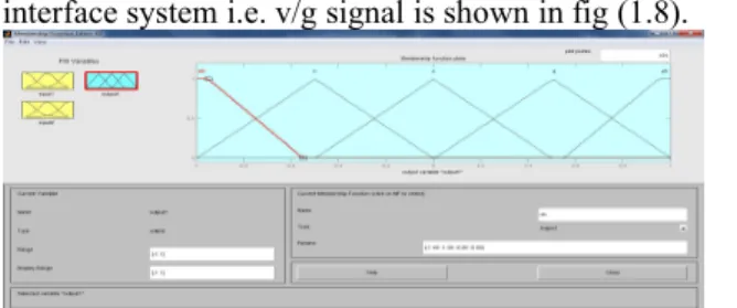
The Membership function editor windows for output of fuzzy interface system i.e. v/g signal is shown in fig (1.8).
Figure 1.8: Membership function Editor for output. RULE BASE
The rule base for the fuzzy logic controller is designed. In this research, the choice of 5 membership functions for each of the two inputs has generated 25 rules for each machine. The rule base employing the rules for two inputs i.e. thevoltage error and the rate ofchange of voltage error, ‘e(k)’ and ‘de(k)’respectivelyarecalculated and normalized. The normalized value of ‘e(k)’ and ‘de(k)’ are given to the FLC as inputs. The input and output fuzzy sets are used both Triangular and Trapezoidal membership function, which are found to be near optimum. The rule base for the FLC is shown in Table-(1.9), and output is line power, voltage and load angle.
Table-1.9. Rule Base for Proposed FLSTATCOM
e(k)\de(k) nh n z p ph Nh nh nh nh n z N nh nh n z p Z nh n z p ph P n z p ph ph Ph z p ph ph ph Where,
nh; negative high, n; negative, z; zero, p; positive, ph; positive high.
From table-1.4, it is clear that each entry represents a particular rule and the stabilized output is obtained by applying a particular rule expressed in the form of membership function. A typical rule has the following structure:
Rule 1: If voltage error, e (k) is nh (negative high)AND change of voltage error de (k) is nh, then the output is nh (negative high).
Rule 2: If voltage error, e (k) is n (negative) AND change of voltage error de (k) is nh, then the output is nh.
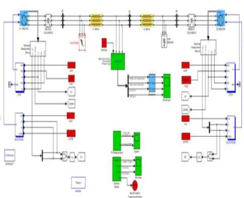
1.10Simulink Modelling
Figure 1.11 2-Machine 3-Bus Test system modelled in Simulink/MATLAB.
Figure 1.12 STATCOM with Fuzzy Logic Controller Simulink Sub Model.
The fuzzy logic controller model with rule viewer connecting with gain value (g = -1495).
Fig:1.13 Simulink diag. of Fuzzy Logic Controller Sub-model
RECORDING OF GRAPHS
The plots obtained for the assessment of the system stability the large disturbances (transient phenomenon) is present in this section. The parameters considered for the assessment are line active power deviation, generator terminal voltage deviation, bus voltage deviation and rotor angle deviation.
Transient Stability Assessment
The system transient performance is enhanced using the fuzzy logic based STATCOM controller in comparison with
conventional STATCOM and without fuzzy logic based STATCOM controller and we show also the response of the system in graphs with faults and without faults. Fig 8.10 shows the line active power deviation responses of n/w generators in interconnected power system without any fault STATCOM and fuzzy logic based STATCOM.
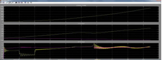
Fig 1.14 Line Active power with FLSTATCOM without any fault The line active power graph is shown in figure (8.11) with LLL-G fault and within 0.10 sec the fault is clear it-self and regain steady state. i.e. transient phenomenon is die-out within operating regions..The bus line voltages (B1, 2, B3) variation in P.u graphs FLSTATCOM without any fault in the proposed system.
The bus line voltages (P.u) variation graphs are shown in figure (1.17) with FLSTATCOM with LLL-G fault at B1. It is clear seen that within 0.10 second fault is clear it-self. i.e. fault clearing time is 0.10sec.
Fig1.15Positive sequence bus bar voltages (P.u) with FLSTATCOM with LLL-G faultat B1.
Figure 1.16 STATCOM output voltage without any fault.
Figure 1.17 STATCOM output voltage with LLL-G fault at B1.
Fig 1.18Load angel of generator in degree with FLSTATCOM without any fault.
Figure 1.19 Load angel of generator in degree with FLSTATCOM with LLL-G fault at B1.
RESULTS ANALYSIS AND DISCUSSION
The performance of proposed system has been studied in a comparative manner with 2 machines, 3 bus system. The assessment of the stability is carried out for transient stability. In this chapter, the results obtained in previous section have been used to reach the final objective of this desperation. The performance of proposed fuzzy logic based STATCOM controller is compared over the LLL-G fault in the system for stability enhancement of a 2 machine, 3 bus interconnected power system.
Analysis of Result
Referring to section (8.3), the fuzzy interface system editor window is shown in figure 8.2 and it is clear indicates that there are two inputs and one output for the proposed FLSTATCOM. The two inputs to the fuzzy logic controller are taken as deviation of voltage and derivative of deviation of voltage of corresponding generator, whereas output of controller is line power and bus terminal positive sequence voltageand load angel deviation. The stabilizing signals are computed using the standard fuzzy membership functions depending upon these variables. The fuzzy interface method is Min-Max type (Mamdani). The defuzzification strategy used is the fuzzy ‘centroid’ method.With reference to section (8.6), the stability of the power system is comprehensively evaluated with the proposed fuzzy logic control scheme, for different case studies using transient performance analysis. The assessment starts with system performance, following small and large disturbances. The stability of the power system then is examined over a wide range of operating conditions. The results obtained for transient stability assessment for the effectiveness of proposed controller is analyzed
Large Disturbances or Transient phenomenon
The system performance for a large disturbance is evaluated by applying self-clearing LLL-G fault at bus B1 within10 sec. duration or 6 cyclesand the same type of fault will be used in all subsequent large disturbance simulations. The system response to a three-phase to ground-fault is analyzed by opening breakers so that fault is clear in 3 cycles.The system assessment for large perturbations is equally important as it contributes to good robustness with respect to changing operating conditions and also good system performance during large perturbations. A comparative study for a large disturbance with system responses are performed with fuzzy logic based STATCOM.With reference to figure (8.10) and (8.11) the results for transient stability assessment are obtained and the plot for the response of line active power (MW) deviation w.r.t
timewithout any fault and with LLL-G faultare shown. The plot clearly indicates that when the system is operating with FLSTATCOM it effectively enhances the system stability and damps all the system oscillations in order to make the system stable within0.10 seconds.
With reference to figure(8.12) and (8.13) the results of transient stability assessment are obtained and plot for
response of Bus voltages (in P.u) deviation w.r.t time without any fault and with LLL-G fault are shown. The plot clearly indicates that when the system is operating with
FLSTATCOM , effectively enhances the system stability and damps all the system oscillations in order to make the system stable within0.10 seconds.
It is observed from the results obtained in section (8.6) that, with the proposed fuzzy logic-based control scheme, the oscillation of inter area tie line active power, speed deviation of respective generator, deviation of voltage and rotor angle are damped little earlier. Therefore, in this research work , it can be said that the proposed FLSTATCOM performs effectively in transient stability.
CONCLUSIONS AND FUTURE WORK
>>ConclusionsIt is seen through this paper study that the novel idea which the researcher designed and implement in MATLAB Simulink which can substantially help to improve the performance of fuzzy logic based STATCOM controller and compared in terms of line active power deviation, Voltage deviation and rotor angle deviation is when LLL-G fault occurs in transmission line. This is confirmed by the simulation and implementation of the proposed system. Therefore, it can be concluded that performance of fuzzy logic based STATCOM controller is observed to be better than conventional STATCOM without fault as well as with LLL-G fault. As it shows , the better control performance is in terms of fault clearing time, damping of transient phenomenon and damping effect.
This paper presents the improved behaviour of transient stability of a 2 machine 3-bus power system using MATLAB software. As power system is a highly complex system and the system equations are nonlinear as the parameters like-voltage, power, speed of alternator etc. are varying due to load fluctuation, faults, lighting, prime mover failure, excitation failure etc. Due to this the stability of alternators becomes disturbed. Mainly transient stability has more dangerous to existing power system alternator.to overcome and compensate these problems without any time delay the Fuzzy Logic Control based STATCOM connect at appropriate location to enhance the transient stability of the system and improve the dynamic response of the system operating in faulty conditions in a better way and it also effectively enhanced the damping of electromechanical oscillations.
According to non-linear simulation results of a multi-machine power system, it is found that the Fuzzy based Controller work well and is robust to change in parameters of the system and to disturbance acting on the system . A Fuzzy Logic Controller combined with a STATCOM controller mechanism is discussed in proposed work. The idea is to combine the advantages of both the controllers to derive a better performance out of STATCOM.
>>FUTURE SCOPE
To reduce the computational complexity of transient stability problems have kept them from being run in real-time to support decision making at the time of a disturbance. If a transient stability program could run in real time or faster than real time, then power system control room operators could be provided with a detailed view of the scope of cascading failure. This view of unfolding situation could assist an operator in understanding the magnitude of the problem and its difficulties so that proactive measure could be taken to limit the extent of the incident. Faster transient stability simulation implementations may significantly improve the power system reliability which in turn will directly or indirectly affect. The studies in this proposed work for two areas two machine, four bus interconnected power system involve the design, optimization,
simulation and implementation of fuzzy logic based STATCOM to stabilize the power system network. The following aspects pertaining to future research into the fuzzy logic-based control strategies in the design of STATCOM are suggested:
a) The work done in this paper is focused voltage error and the rate of change of voltage error as input variables. The fuzzy logic based STATCOM with frequency as input parameter can be investigated since the frequency is highly sensitive parameter in weak system.
b) The design and implementation of fuzzy logic based STATCOM using more complex interconnected power system network can be performed in future.
c) Although the optimized fuzzy logic based STATCOM controller has been implemented using MATLAB Simulink and the results are observed to be satisfactory, the methodology need to be implemented in the actual interconnected power system in the future.
In addition to real time analysis, there are other areas where transient stability analysis could become an integral part of daily power system operations.
a) System restoration analysis. b) Economic / environmental dispatch. c) Expansion planning.
REFERENCES
1. P. Kundur 1994, “Power system stability and control”, McGraw Hill.
2. M. John Bosco and A. Darwin Jose Raju “Power System Stabilizer Using Fuzzy Logic Controller in Multimachine Power Systems”IET-UK International Conference on Information and Communication Technology in Electrical Sciences (ICTES 2007), Dr. M.G.R. University, Chennai, Tamil Nadu, India. Dec. 20-22, 2007. pp. 132-136.
3. L. Sunil Kumar and A. Ghosh, “Modeling and control design of a static synchronous series compensator.” IEEE Transactions on Power Delivery, 14(4): 1448-1453, Oct. 1999.
4. A Luo "Fuzzy-PI Based Direct Output Voltage
Control Strategy for the STATCOM used in Utility distribution system", IEEE Transactions on Industrial
Electronics, Vol.56, No. 7, pp 240-24 1, 2009.
5. G. Hingorani and L. Gyugyi, “Understanding FACTS, Concepts, and Technology of Flexible AC Transmission Systems”, Piscataway, NJ: IEEE Press, 2000.
6. M.H. Haque, “Application of energy function to assess the first swing Stability of a power system with an SVC”, IEE Proc. Gener. Transm, Distrib. Vol.152, No.6, Nov.2005, pp.806-812.
7. M.H. Hague, “Improvement of first stability limit by Utilizing full benefit of shunt FACTS devices”, IEEE transactions on power systems, vol. 19, no.4, pp. 1894 – 1902. November 2004.
8. H.F. Wang, “Static synchronous series compensator to damp power system oscillations”, Electric Power System Research, vol.54, no.4, pp.113–119. 2000. 9. P.L. So, T. Yu, “Coordination of TCSC and SVC for
Interarea stability Enhancement” IEEE Trans. on Power Delivery, Vol. 9, No. 1, 2000.
10. H. Ying, “TIT0 Mamdani Fuzzy PI/PD Controllers as Nonlinear, Variable Gain PI/PD controllers”, International Journal of Fuzzy System, Vol. 2, No. 3, September 2000.
11. A. Kazemi and M.V.Sohrforouzani, “Power system damping using Fuzzy controlled FACTS Devices”, International conference on Power system Technology, POWERCON 2004, Singapore. 12. M Noorzian and G Anderson (1994)“Damping of
Power System by Controllable Components”IEEE Transactions on Power Delivery, vol 9, no 4, p 2046. 13. J Lee (1993) “On Methods for Improving Performance of PI-type Fuzzy Logic Controllers”IEEE Transactions on Fuzzy Systems, vol 1, no 4, N, p 298.
14. M. Barakati, S. Khanmohamadi, S. H. Hosseini, “Improving the Power Stability using Fuzzy Logic Controlled Static Var Compensator”, The 4th Iranian Conference on Electrical Engineering, ICEE-97, 1996.
15. Timothy J. Ross, “Fuzzy Logic with engineering application”, McGraw- Hill, Inc. 1995.
16. Qun GU, Anaemia Pandey and Shelli K Starrett, “Fuzzy logic control schemes for static VAR compensator to control system damping using global signal”, Electric Power Systems Research, Vol.67, 2003, pp. 115.
17. Mori S, Matsuno K, Takeda M, Seto M. “Development of a large static var generator using self-communicated inverters for improving power system stability” IEEE Trans Power System 1993;8(1):371–8.
18. ZIMMERMANN, H.J. “Fuzzy Set Theory and ItsApplications”(Kluwer-NijhoffPublishingCompan y, 1985)
19. Sedghisigarchi, Kourosh, and Ali Feliachi. "Dynamic and transient analysis of power distribution systems with fuel Cells-part I: fuel-cell dynamic model."Energy Conversion, IEEE Transactions on 19.2 (2004): 423-428.
20. Srithorn, Phinit, et al. "Power System Stabilisation Using STATCOM with Supercapacitors." IndustryApplications Society Annual Meeting, 2008. IAS'08. IEEE, 2008.
21. HaiFeng wang “A Unified model for the Analysis of FACTS devices in damping powersystem oscillation-part-ITI, UPFC”, IEEETran. on power delivery, vol. 15, no.3, July2000, pp.978-983.