Abstract—This paper describes the system design and implementation of a vehicle management system and covers the following five sections: (1) GPS signal. (2) Microcontroller functions. (3) SD card storage technology with FAT32 file system. Most MCU use FAT16 file system to manage files, but it wastes a lot of memory space when small files are stored to each cluster. Using the FAT32 file system will ensure an efficient use of the memory space. (4) GPRS transmission. (5) Real-time monitoring Server, which is used to monitor vehicles accurately in real-time. The system adopts a web-based solution aimed at gathering the information of vehicle’s status and location in real-time. The location information is exposed with geographic coordinates, computed by a GPS processor in vehicle. The processor is embedded in the proposed device, a driving recorder, installed on a vehicle and responsible for transmitting location information to monitoring server. The recorder is a portable, highly accurate, and low powered vehicle tracking device, implemented with TI MSP430F5438 microcontroller.
Index Terms—MSP430F5438, Vehicle Management System, FAT32
I. INTRODUCTION
In recent years, with the continuous development of the economy, automobiles have gradually entered our lives. Although the vehicle is the most common transport, it is also one of the modes of transportation most frequently involved in traffic accidents.
In order to record and manage enough vehicle driving information to provide the necessary evidence in a traffic dispute, the intelligent driving recorder becomes more widely used.
The driving recorder can be generally divided into the traditional mechanical driving recorder and digital driving recorder. The traditional mechanical driving recorder has low accuracy, requires a long processing time, and is prone to error. In comparison, the digital driving recorder is convenient in data transmission and management, and has fewer errors, advantages of expandability, the possibility of integration, and the capability to record different data combinations according to requests.
This paper implemented a Vehicle Management System based on MSP430F5438 which carries out a solution with low cost, low power consumption, real-time processing, and high stability.
II. SYSTEM DESIGN
Fig. 1 shows the structure of the system. First of all, the system receives data from the GPS receiver. Through GPS and digital transmission, we can then collect the related vehicle’s moving data, including longitude, latitude, driving
speed, time, and date. All of that GPS data is sent to MSP430F5438 by the Universal Asynchronous Receiver/Transmitter (UART). GPRS also uses UART to transmit. There are two ways to process the data from the MSP430F5438 microcontroller shown in Fig. 1. The primary way is using a GPRS module to transmit vehicle information to management server for instantaneous monitoring. The second way is using Serial Peripheral Interface Bus (SPI) to access SD card. Stored trajectory data on SD card can be retrieved afterward if vehicle instantaneous information received by management server not successfully.
In accordance with FAT32 file system, specification based on SD card file system is implemented. An underlying SD card process was developed and integrated with the FAT file system, which enables rapid file storage when developing an embedded system. The data of real-time collection can be stored on the SD card in the form of text by the file system in a short time. If GPRS has no signal, the trajectory of the vehicle can be obtained from the SD card. The back-end server works via GPRS wireless communication and the Internet. The real-time monitoring server processes the spatial coordinates, real-time location, driving speed, time, date, and vehicle trajectory for producing the relative maps to achieve the purpose of real-time monitoring. At the same time, GPS data is still written to a file on the SD card continuously.
Fig. 1. The structure of system
A. Data Collection
This system receives the digital data from GPS. The GPS data includes longitude, latitude, speed, UTC time, date, and message produced from the mobile vehicles. The user can operate the real-time system to control the vehicle position status.
Many GPS receivers provide navigational output data so that the device can be connected, for example, to a PC to collect and analyze this data. This output data is usually in serial format and the communication protocol conforms to
The System Design and Implementation of Vehicle
Management
the RS232 serial standards.
Using the MAX3232 generates the required negative voltage for a RS232 line and translates the TTL level signals from the MSP430F5438 levels to RS232 levels [1]. The MAX3232 board is used for establishing RS232 communication with devices powered from 3V ~ 5V. It contains RS-232 Transceiver and DB9 connector used for connecting PC and MCU.
The default serial communication parameters of most GPS receivers are set as follows [2]:
1) 4800 Baud rate. 2) 8 data bits 3) No parity bit 4) 1 stop bit
The data output from a GPS receiver is in ASCII text format and is known as the NMEA-0183, or simply the NMEA format [3]. According to this format, navigational information is sent in the form of “sentences”, where each NMEA sentence starts with a “$” sign, each navigational parameter is separated by commas, and each sentence is terminated by two hexadecimal checksum characters.
The NMEA sentence used in this system is the $GPRMC, which has the following parameters: $GPRMC: Although there are some variations in its format, this sentence basically defines the basic navigational parameters, speed, course, date of fix, and magnetic variation. An example is:
$GPRMC,132031.000,A,2502.5585,N,12125.4856,E,12.8 1,354.81,100512,,,A*51
GPRMC format is described in Table I. TABLEI:GPRMCFORMAT
B. Data Processing
TI’s MSP430F5438 is used as the processor of this Vehicle Management System. The processor was chosen because of its good features and integrated peripherals. Its portability and low-power consumption design can satisfy the prolonged outdoor work.
MSP430F5438 Microcontrollers (MCU) from Texas Instruments (TI) is a 16-bit, RISC-based, mixed-signal processor designed specifically for ultra-low-power [4]. It is combined with a flexible clock system by using a Von-Neumann common memory address bus (MAB) and a
memory data bus (MDB). Fig. 2 shows the architecture of this microcontroller. MSP430F5438 has the right mix of intelligent peripherals, ease-of-usage, low cost, and the lowest power consumption for thousands of applications. Its flexible clocking system, multiple low-power modes, instant wakeup, and intelligent autonomous peripherals enable true ultra-low-power optimization, dramatically extending battery life [5]. Its power modes are shown in Table II. The system is running in Active Mode. If the process is finished, the system will be in Standby Mode.
Fig. 2. MSP430F5438 architecture TABLEII:MSP430F5438POWER MODES
Fig. 3 shows hardware connection, and the work flow of the MSP430F5438 is shown in Fig. 4. After turning on the device, it automatically initializes the hardware, file system and SD card. Then it gets the GPS data in NMEA 0183 format of GPRMC. This GPS data will be placed in RX_buffer. It creates files by date, so, if the device turns on for the first time, FAT32 will create a new file on the SD card and write data from RX_buffer. It then tries to connect to GPRS. If it fails due to GPRS unavailability, then the data is still stored on SD card, and it tries to connect to the GPRS again. After establishing the GPRS connection, it tries to connect to the service provider’s server using the HTTP protocol. If the connection is successful, the GPS data will be sent to the server as a string. In this way, the device communicates with the server and sends the current location.
Fig. 4. Processing flowchart of the system
C. Data Storage and File Management
The system is equipped with a removable sending SD (Secure Digital) card, which is used for GPS data storage. Saving the acquired data by this type of storage media is appropriate not only because of its large capacity, but also because of the subsequent processing of stored data, which is performed in the service application on a PC of Windows. If GPRS service fails, the past trajectory information of the vehicle can still be obtained from the SD card.
In order for the system to read and write from the SD card, the SPI (Serial Peripheral Interface) from MSP430F5438, shown in Fig. 5, is used. The number of signals of SPI (three or four wires) is larger than IIC's two wires, but the transfer rate can rise up to 20 Mbps or higher depending on the device's ability (5~50 times faster than IIC). The SPI interface permits communication with only four physical connections. The basic configuration consists of a clock signal, a Slave In Master Out (SIMO), a Slave Out Master In (SOMI) and a Slave Select (CS), besides 3.3V and GND [6]. When interfacing multiple slaves to a single master, the slave ICs can be attached in parallel, and separate CS signals from the master IC are connected to each slave ICs. The data output of the slave IC is selected by which CS signal is enabled, and deselected devices are disconnected from the MISO line.
Fig. 5. SPI single Master / Slave application
For the SD Memory Card protocol, the SPI messages consist of command, response and data-block tokens [7]. All communication between the host and the cards is controlled by the host (master). The host starts every bus transaction by asserting the CS signal low.
The SD commands are shown in Table III. TABLEIII:SDCOMMANDS OF SPIMODE
To make managing the data easier, the FAT32 file system support was implemented in the processor. FAT32 uses space more efficiently than FAT16 [8]. Table IV shows the cluster size, comparing FAT32 with FAT16. FAT32 uses smaller clusters (4 KB for drives up to 8 GB), resulting in 11 to 15 percent more efficient use of disk space compared to large FAT16 drives [9]. FAT32 also reduces the resources necessary for the MCU to operate. The boot record on FAT32 drives has been expanded to include a backup of critical data structures [10]. This means that FAT32 volumes are less susceptible to a single point of failure than FAT16 volumes.
D. Wireless Communication
On this system, the user can send out wireless communications by GPRS, text, and status messages. Thus, a powerful communications tool is created, enhancing the organization's performance and efficiency to achieve the purpose of real-time monitoring.
The GPRS of system is integrated with the TCP/IP protocol; extended TCP/IP AT commands are developed so the user can utilize the TCP/IP protocol easily, which is very useful for those data transfer applications.
AT command is shown in Table V. TABLE IV: FAT32VS. FAT16
The GPS data is sent via GPRS service from the GSM network to a web server using the HTTP protocol [11].
Real-time Monitoring is the major part of this system. This enables the user to view the live position of a vehicle on the map. Google Map Satellite version is used to locate the position.
The server is a web-based application developed by Java Programming, and it uses PostgreSQL as the database server. The data from the data collector is stored in the PostgreSQL database. The data includes vehicles’ information, coordinates, and position. PostgreSQL is chosen to be the database because it is light-weighted, scalable and able to support many platforms. Java framework, such as Hibernate, is chosen to be used in this system to make it standardized and easy to develop. JSP is used for web presentation. Google Map is used for showing vehicle information, and AJAX technology is enhanced to enable more real-time web interface. The server diagram is shown in Fig. 6. Fig. 7 shows the architecture of the server.
Fig. 6. Server diagram
Fig. 7. Data collection server III. EXPERIMENT RESULTS
To view the current position of the vehicle, a web-based application has been developed. Using this web application, an end user will be able to view the live position of the vehicles and also see the past trajectory stored on the SD card.
After program coding and function testing, the information system was carried out for vehicle management. It can monitor several vehicles. The server snapshot is shown in Fig. 8.
Fig. 8. The real-time position of the monitoring vehicle by using Google map
B. Trajectory History from the System
To ensure that the system’s functions work, a data set collected on-site with the designed scenarios was operated on by the system to test its effectiveness in an off-line basis.
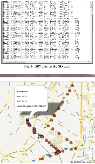
Fig. 9 shows the vehicle’s trajectory. It also contains GPS data that we need.
The system obtains the GPS data from the SD card, and it then inserts the SD card into a PC to view the trajectory history of a vehicle. This part is shown in Fig. 10.
Fig. 9. GPS data on the SD card
Fig. 10. Trajectory history of vehicle
E. Real-Time Monitoring Server
IV. CONCLUSION
This paper presents a low power and low cost Vehicle Management System using MSP430F5438, SD card, FAT32 File system, GPS, and GPRS of GSM network that is suitable for a wide range of applications all over the world.
The combination of the GPS and GPRS provides continuous and Real-time Tracking. Data is integrated and transmitted to a web server using Apache’s Tomcat extensions to provide Internet access via a vehicle tracking website. The FAT32 file system was developed to replace the older FAT16 technology. It allows for larger disk partitions and a smaller cluster size, resulting in less wasted disk space. It is more efficient for storing the GPS information of a vehicle.
This system focused on using the FAT32 file system for management, GPS information, and a web-based server has been developed.
REFERENCES [1] MAXIM, “MAX3232CSE Data Sheet,” 1999. [2] HOLUX, “GR-213 User's Guide,” 2005.
[3] NMEA 0183 Standard for Interfacing Marine Electronic Devices, Version 2.0, National Marine Electronics Association, Mobile, AL, January 1992.
[4] Texas Instruments, “MSP430F5438 Data Sheet,” 2006. [5] Texas Instruments, “MSP430Fx5xx Family User's Guide,” 2006. [6] Texas Instruments, “Using SPI synchronous communication with data
converters: interfacing the MSP430F149 and TLV5616,” 2005. [7] Texas Instruments, “Interfacing the MSP430 with MMC/SD Flash
Memory Cards,” 2006.
[8] Group (MEI, SanDisk, Toshiba), SD Memory Card Specifications Part 2 File System specification, Version 1.0, 2000.
[9] A. Evans, “Fat16 Interface for MSP430, Application Note,” Dept. of Electrical and Computer Engineering, Michigan State University, 2004.
[10] Microsoft Corporation, Microsoft Extensible Firmware Initiative: FAT32 File System Specification, Version 1.03, 2000.
Jr-Jen Huang received the B.S.E.E. degree from
Chung Yuan Christian University, Taiwan, R.O.C., in 1988, and the M.S.E.E. degree from the State University of New York, Binghamton, in 1991, and the Ph.D. degree in electrical engineering from Purdue University, West Lafayette, IN in 1999. Dr. Huang is currently an assistant professor at Ming Chi University of Technology, Taiwan and his research interests include nonlinear signal and image processing techniques, estimation under the mean absolute error criterion, perceptual error measures, stack filters and applications of LBS system.
Dr. Huang received Outstanding Teacher Awards from Ming Chi University of Technology class of 2009 and Taiwan Private School Society in 2010. Dr. Huang has been serving as the director of Library and Information Services of Ming Chi University of Technology, Taiwan since 2010.
Yi-Yu Chu received his B.S. in Electronic
Engineering from Ming Chi University of Technology, Taiwan, R.O.C., in 2010. Mr. Chu is a postgraduate at Ming Chi University of Technology, Taiwan, and his research interests include vehicle management system,vehicle dynamics, embedded system, and web application development.
Yen-Jen Chen was born in Taiwan. He received the
B.S. and Ph.D. degrees in computer science and information engineering in 1989 from Tatung Institute of Technology and in 2000 from National C h i a o Tu n g U n i v e r s i t y ( N C TU ) , T a i w a n , respectively. From October 2000 to July 2001, he was an Assistant Professor under the collaboration project of NCTU and Cisco Systems Inc. for developing VoIP Testing Technology. From August 2001 to August 2002, he was a network design consultant in Unisys Corporation, Taiwan. Since August 2002, he is an Assistant Professor in the Department of Electronic Engineering, Ming Chi University of Technology, Taiwan. His research interests include traffic engineering and quality of service in computer networks, network management and system integration, and cloud virtualization.
[11] J. Cai and D. Goodman, “General Packet Radio in GSM,” IEEE Communications Magazine., vol. 35, no.10, pp. 122-131, 1997.