Web Page Manual
GOLD RX, PX, CX, SD Program Version 5.00 or better
GOLD LP/COMPACT Program Version 2.00 or better
1. GENERAL
The air handling unit has a built-in web server that enables you to monitor, enter and change the settings in the air handling unit.
Access to this server requires a web browser with support for SUN Java and that the JRE Version 6 Runtime Environ-ment (or a later version) is installed in the computer you will be using. You can download the later SUN Java soft-ware from www.java.com.
2. CONNECTION
The computer and air handling unit can be connected to one another in two different ways: by means of a crosso-ver cable or with a network hub (HUB, switch or router). The determining factor as to whether or not a network hub can be used, may be how many units are to be con-nected together, for example. Two units can be concon-nected together without any network hub.
Examples of when two units are connected together are: when a computer and a GOLD/COMPACT air handling unit are connected together, or when two GOLD units (RX/PX/CX/SD only) are to be connected together in order to use the same modem. Two or more units can be con-nected together with a network hub.
The network connection is situated on the control circuit card of the air handling unit. See the Installation Instruc-tions or the Operation and Maintenance InstrucInstruc-tions.
2.1 Connection between two units
A cross-connected CAT5 cable with RJ45 contacts, see Figure 2, should be used for the connection of one or more GOLD/COMPACT air handling units to a computer/ network via hub, switch or router. The cable should be of twisted-pair type, and can be shielded or unshielded.
2.2 Connection between two or more units
A straight (not cross-connected) CAT5 cable with RJ45 contacts, see Figure 3, should be used for the connection between several GOLD/COMPACT air handling units and a computer/network, or between a GOLD air handling unit
1 2 3 6
3 6 1 2
GOLD/
COMPACT Computer
1 1
GOLD/ COMPACT
GOLD/ COMPACT Computer
* GOLD * FRI 08:20
STOP?
MAN/AUTO. OPERATION
SETTINGS
INSTALLATION
i
COMMUNICATION
* COMMUNICATION *
EIA232
EIA485
ETHERNET
* ETHERNET *
MAC ID
DHCP-SERVER
IP-ADDRESS
* DHCP-SERVER *
INACTIVE
CHANGE?
3. AIR HANDLING UNIT SETTINGS
On delivery, the control circuit card has a static IP-address set to 10.200.1.1. To assign the circuit card another static address, change the Subnet mask and Gateway or activate the DHCP, do as follows:COMPACT Air & Heat only
In order to progress advance from the start menu, high-light >> the lowest line and acknowledge by pressing the Enter button.
Enter code 1110.
All
From the initial position, navigate downward and select SETTINGS.
Navigate forward to INSTALLATION. Enter code 1111 in order to enter the submenus of the Installation section. Press Enter.
Navigate forward to COMMUNICATION. Press Enter.
Select ETHERNET in the COMMUNICATION menu.
Select DHCP-SERVER in order to activate/deactivate the DHCP.
DHCP active = The network’s server assigns the air
handling unit an IP-address/subnet mask/Gateway and DNS.
DHCP inactive = Manual setting of IP-address/subnet
mask/Gateway and DNS.
Select CHANGE and then DEACTIVATE or ACTIVATE
NORMAL
OPERATION
OVERTIME
OPERATION
AIRING
>>
* ETHERNET *
MAC ID
DHCP-SERVER
IP-ADDRESS
* IP-ADDRESS *
010
.200.001.001
MAC ID
DHCP-SERVER
IP-ADDRESS
SUBNET MASK
* SUBNET MASK *
255.000.000.000
DHCP-SERVER
IP-ADDRESS
SUBNET MASK
GATEWAY
* GATEWAY *
000.000.000.000
Select IP-ADDRESS if you instead want to change or check the IP address.
You can set the address here, or you can read what address the DHCP-server has assigned to the air handling unit. You cannot change the IP-address as long as the DHCP is activated. You must fi rst deactivate the DHCP server before you can change the IP-address.
Select SUBNET MASK in order to change or check the Subnet mask.
Keep in mind that you should select an IP-address and a subnet mask that are in agreement. If the DHCP-server is active, you will not be able to change the subnet mask.
Change or check the subnet mask here.
Select GATEWAY in order to change or check the Gate-way.
If the DHCP-server is active, you will not be able to change the gateway.
Change or check the Gateway settings here.
Select MODBUS TCP in order to change or check the MODBUS setting.
Under MODBUS TCP, access via MODBUS might be lim-ited. For example, if you want to allow only one client access with an IP address of 10.200.1.10, this IP-number should be specifi ed and the subnet mask should be set to 255.255.255.255. If the factory setting is used (according to the image) all clients are allowed access.
N.B.! Port 502 must be open in a possible fi rewall in order for MODBUS TCP to operate correctly. The MODBUS TCP server replies to address 1-247 only.
IP-ADDRESS
SUBNET MASK
GATEWAY
MODBUS TCP
* MODBUS TCP *
IP 000.000.000.000
SUBNET M.
4. REMOTE CONNECTION
(GOLD RX/PX/CX/SD only)
N.B.! When connecting up with GSM for the fi rst time, see Section 7.11.
You must establish a remote connection from the compu-ter you are using in order to connect up to the modem of the air handling unit.
Remote connection can be established in various ways depending on what operative system is installed in your computer. Therefore, if you have any questions, you should get in touch with the support group of your local computer supplier.
Note that you must specify your user name and password for the PPP server. See Section 7.12. The basic setting is user name = admin, password = admin.
5. TO LOG ON
Sun Java must be installed and activated. Sun Java can be activated at various places depending on the operative system and web browser in use. For more help, get in touch with your local computer support group.
Start the web browser and enter the IP address for GOLD/ COMPACT (Factory setting http://10.200.1.1). A dialogue box opens, where you should enter your user name and password.
Depending on your user name and password, the ap-propriate authorization, reader, writer, service and admin status are allocated.
The fi rst time you log in enter the following: User name = admin
Password = admin
N.B.! When you change the password, the new password must not consist of more than 15 characters.
Then select the appropriate language to be used in the web interface. Press the button by the appropriate lan-guage to make your choice.
Tip! In order to not have to log in and select language every time you visit a certain air handling unit, you can save a Favourite in your web browser for connecting directly to the page that you wish to use as the starting page.
A link to http:// 10.200.1.1/cgi/pagegen?page=start enables the user to directly access the fl ow chart image for air handling unit 10.200.1.1 without having to log on and select language (provided that the user has done so at some earlier point in time).
User Read
values
Change setpoints:
Change control
para-meters
Access the admin tap Reader
Writer Service Admin
6. USER LEVELS
At the ”reader” level, all the tabs other than the admin tab are accessible. You can only view the readings; you CANNOT change them. You can reset any tripped alarms to zero.
At the next level, “writer”, you have the right to change setpoints. See regulation signals, change the clock and a number of control functions.
At the ”service" level, you are also given the right to change all the control parameters. The Admin tab is still inaccessible.
At the ”admin” level, you have full rights to access and change settings. With this authorization it is possible to change the IP confi guration, link tables, etc.
7. TABS
The settings and readings can be viewed under various tabs. For particulars of the specifi c control functions and settings, refer to the Operation and Maintenance Instruc-tions for the GOLD/COMPACT units; or whenever applica-ble the corresponding functional guide.
Note that any changes you make via the web interface will not be saved in the long-term memory of the air handling unit until one hour has elapsed after the change was made. On the other hand, the change is effective imme-diately as soon as it is entered since it is then in the short-term memory of the air handling unit.
This means that if a power failure occurs or if the air han-dling unit is restarted for some reason, the values that were in force before the change will be re-created on the next start up. This does NOT apply to changes that were entered under the Admin tab. These changes are saved as soon as they are entered.
The control parameters for the functions that are not activated are concealed and therefore are not visible on the page. In order to produce the control parameters, the function must accordingly be activated.
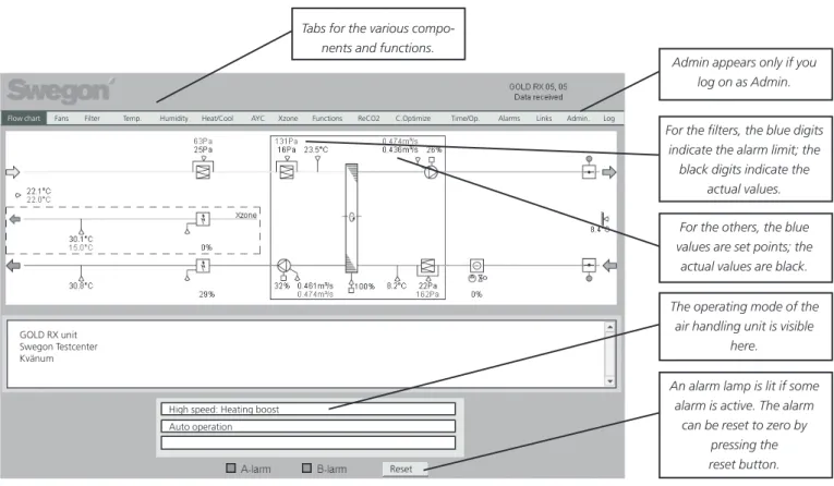
Admin appears only if you log on as Admin.
For the fi lters, the blue digits indicate the alarm limit; the
black digits indicate the actual values. For the others, the blue values are set points; the actual values are black. The operating mode of the
air handling unit is visible here.
An alarm lamp is lit if some alarm is active. The alarm
can be reset to zero by pressing the reset button.
7.1 Flow chart
The fl ow chart is shown as a starting page when you con-nect up to the air handling unit, provided that the admin-istrator has not specifi ed a different page. No settings can be made here other than the resetting of alarms to zero. The purpose of the fl ow chart is to provide a quick over-view of the air handling unit and its current readings. The fl ow chart shows both the preset and the actual values for settings such as supply air, extract air, supply air tempera-ture, etc.
If you are logged on as someone other than the Adminis-trator; the Admin tap will not be visible.
Tabs for the various compo-nents and functions.
The values in the blue
trian-High speed: Heating boost Auto operation GOLD RX unit
Swegon Testcenter Kvänum
Reset
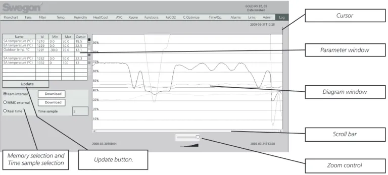
Cursor
Parameter window
Diagram window
7.2 Log
The parameter window can contain a maximum of ten param-eters at one time. The parameter number is the internal ID of the parameter and can be used for making sure that the parameter you are referring to is the right one when you seek support, for instance.
In order to study a parameter, the user should click on an empty line in the parameter window for adding a new parameter, or click on an already existing parameter for the purpose of exchanging it. A new window will then pop up where you can select a parameter. If the user clicked on an existing parameter, it is also possible to delete it by pressing Delete.
Min and Max are min. and max. signal values. These values can be changed by the user in order to obtain a different resolution in the diagram window.
The value of the parameter at the point where the cursor cur-rently is in the diagram window is shown in the Cursor column. A box, coloured the same as the parameter curve in the diagram window, is shown to the right of the parameter window. The curves of the parameters that have been selected in the parameter window are shown in the diagram window. The Y axis is graded from 0 – 100 % where 0 % corresponds to a param-eter’s min. value and 100% corresponds to the paramparam-eter’s max. value.
To study a parameter’s value at a given point, click with the mouse on the relevant point in the diagram. The cursor will then hop to the place where the user clicks. The value at the point where the cursor rests is displayed in the Cursor column in the Parameter window.
By using the zoom control, the users can zoom in (move the control to the left) and zoom out (move the control to the right). If the control is moved to the right as much as possible, all the points in the current memory will be visible. If the zoom control is not completely zoomed out, it is possible to move the diagram to the side using the scroll bar. .
Two times are shown at the lower left and lower right edge of the diagram window. They show the time at the data points that are at the beginning and end of the diagram.
In the Memory selection box, the user can select the memory from which data will be studied.
RAM internal: is always accessible. Memory size: 2000 KB This is suffi cient for the collection of data for approx. 200 hours, pro-vided that the time between two data points is 5 minutes. The RAM memory will be erased in the event of a power failure.
MMC external: can be used if the user has inserted an MMC card in the MMC card holder for MMC cards in the air handling unit. The log fi le on an MMC card is restricted to 65,000 log events (approx. 40 MB). When the air handling unit has logged up to 65,000 log events, the next value is logged at the begin-ning of the fi le.
Real time: downloads data in real time and displays the data in the diagram window. The period between two data points can be selected in the time sample box. The shortest time is one second. Note that it takes a while before a time will be displayed to the left below the diagram window since it takes a while for the fi rst saved point to appear at the extreme left.
The period between two data can be set under Admin – Misc or by means of the hand terminal except for the real-time mode. If the user uses the RAM or MMC and some time has elapsed, the user can press the Update button to make sure that the last data point will also appear in the diagram window. If the user uses the RAM memory, he or she can update the display by clicking on RAM one more time. The same applies to the MMC memory.
By clicking on the "Download" buttons, the user can save the relevant log fi les locally in the connected computer. The fi les are of xls.gz type. Use an unpack software, such as Winzip, to unzip the log fi les. When the fi les have been unzipped, they can be opened in Microsoft Excel or a similar program.
Update
Flowchart Fans Filter Temp. Humidity Heat/Cool AYC Xzone Functions ReCO2 C.Optimize Time/Op. Alarms Links Admin Log
Name Id Min Max Cursor SA temperature (°C) 1210 0.0 50.0 18.5 EA temperature (°C) 1229 0.0 50.0 22.5 Outdoor temp. °C 122F -30.0 70.0 12.1 SA temperature (°C) 1242 0.0 50.0 22.3 SA temperature (°C) 1332 0 100 13
Ram internal Download MMC external Download Real time Time sample 5
7.3.1 Admin – Users
Users can be managed under this tab. Here, you can specify who has access to web pages as well as how and who you should inform in the event of possible alarms. You can also enter a password for each user here. N.B.! The passwords and user names must not contain characters with accents of any kind used for indicating the quality of a vowel, for instance.
The initial setting for passwords for the various user names are as follows:
User Password
reader reader
writer writer
service service
admin admin
Alarms can be sent via e-mail if the air handling unit is connected to the network/Internet via a local network.
GOLD RX/PX/CX/SD only
Alarms can also be sent via an analogue modem or GSM modem. If a GSM modem is connected to the air handling unit, alarms can also be sent as text messages (SMS). If required, the GSM number to the recipient must be entered and the SMS boxes must be marked with an X. If you are sending a message to a foreign GSM telephone with the number such as 070-12 34 56, you must fi rst enter the country’s exchange code: +46 70 123 456.
7.3.2 Admin – TCP/IP
The settings for network communication with the air han-dling unit can be entered under the TCP/IP tab.
For information about suitable settings, please get in touch with your local computer support group.
7.3 Admin
The Admin tab is shown only for users who have been granted administrator rights.
Flowchart Fans Filter Temp. Humidity Heat/Cool AYC Xzone Functions ReCO2 C.Optimize Time/Op. Alarms Links Admin Log
User TCP/IP E-mail PPP-server Flowchart Links Misc. MMC
7.3.3 Admin – E-mail
You can select here whether the air handling unit shall manage outgoing e-mail, or whether some other air han-dling unit connected to the network shall do this. If the air handling unit shall manage the e-mail, fi ll in SMTP-server. This address can be a domain name or an IP address. If a domain name is used, the required and alter-native DNS should be fi lled in below the TCP/IP tab. E-mail reply-path can be the same as the sender address, if the air handling unit has a unique e-mail address of its own.
It is often appropriate to enter the address to the person who is responsible for the air handling unit in both e-mail address boxes.
When it comes to communication, the air handling unit can operate as a master or slave in a network with several air handling units.
If the air handling unit is a master, the e-mail setting should be according to the fi gure below. *If the air han-dling unit is a slave in this network, the IP address of the master unit should be fi lled in on the ALARM gateway line and the Local alarm gateway should not be activated. PPP client should not be fi lled in if the air handling unit is used as a slave.
If you are uncertain as to which IP number an air handling unit has, you can always fi nd it using the hand-held termi-nal of the relevant air handling unit. See the introduction in this document.
GOLD RX/PX/CX/SD only
PPP client should be fi lled in if an air handling unit has a modem connected to it and this unit can connect up and e-mail an alarm message. Set the PPP client to active, a call should be placed to the appropriate telephone number and, if required, you should fi ll in your login and pass-word. Select the type of modem used and, if required, fi ll in your PIN code to the GSM module.
You must fi ll in the correct type of modem. If you use a PIN code on a SIM card for the GSM modem, it should also be entered here.
If the SIM card requires a PIN code and you do not enter it here, your SIM card is likely to be blocked and must then be unlocked with a so-called PUK code to make it work again. For more information, contact your GSM operator. If necessary, also check specifi c commands for the
modem. These AT commands are written in under Modem initialization string.
If the modems recommended by Swegon (TBLZ 2-3-41-1 and TBLZ 2-3-41-2) are used, you need not make any changes. The e-mail sender is the e-mail address, which will be entered as the sender on e-mail sent from the air handling unit.
Flowchart Fans Filter Temp. Humidity Heat/Cool AYC Xzone Functions ReCO2 C.Optimize Time/Op. Alarms Links Admin Log
User TCP/IP E-mail PPP-server Flowchart Links Misc. MMC
E-mail server External SMTP server External SMTP Port number External SMTP Login
External E-mail server (ISP) 172.16.0.247
25
External SMTP Password E-mail sender E-mail reply-path Local alarm gateway
[email protected] [email protected] Active
E-MAIL SETTINGS
Alarm gateway IP 127.0.0.1
PPP client Telephone Login Password
Inactive
7.3.4 Admin – PPP server (GOLD RX/PX/CX/SD only) PPP server settings
This function is activated for the purpose of making it pos-sible to place a call to the relevant air handling unit. The user name and password of the current user must be fi lled in. When contact is established, the unit’s usual login procedure is valid.
The air handling unit allots a predetermined IP address to users connecting to the network (see Figure below “Allot-ted IP address”. This contact should therefore be estab-lished with the support of Dynamic Host Confi guration Protocol (DHCP).
Routing settings
The function for routing between several GOLD units con-nected together in a network of their own with one unit operating as master can be activated here.
The main unit will be the one with connected modem/ network. All the units included in the network can be contacted via this unit.
N.B.! If a modem in use serves several GOLD units, the Server IP address and allotted IP address should not be in the same number series as the IP address under TCP/IP.
Flowchart Fans Filter Temp. Humidity Heat/Cool AYC Xzone Functions ReCO2 C.Optimize Time/Op. Alarms Links Admin Log
User TCP/IP E-mail PPP-server Flowchart Links Misc. MMC
PPP server User name Password Server IP address
Inactive admin admin 10.200.1.3 Assigned IP address
Modem type GSM PIN code
Modem initialization string
10.200.1.2 Modbus RTU
PPP-SERVER SETTINGS
Routing Inactive
7.3.6 Admin – Links
Under this tab, you can set whatever links you want shown below the Links tab in the upper menu bar. Here you can create quick-access links to the other air handling units that are included in the network. Fill in the name and IP addresses to the connected units.
7.3.7 Admin – Misc.
The settings for the external logging and logging interval can be entered under the Misc. tab. There is also a section for limiting access via Modbus TCP.
7.3.5 Admin – Flowchart
If the fl ow chart shall correspond to the component sec-tions in and around the relevant GOLD/COMPACT unit, the boxes of the external dampers connected to the air handling unit must be marked with an X in order for them to be visible in the overview image seen by the other users. These X markings must be made in the overview image.
An optional text can be written in the box under Flow-chart. This text enables you to quickly identify the air
han-dling unit, in the event of an alarm sent via e-mail or text message (SMS), or if the page is read via a web browser. At the very bottom, it is possible to select how the image will be shown. You can change the image so that it will refl ect how the air handling unit is constructed in reality. For particulars of the specifi c control functions and set-tings, refer to the Operation and Maintenance Instructions for the GOLD/COMPACT units.
version 5.08 or better is required for SD cards.) If an MMC card or an SD card is in the memory card holder, the con-trol unit can log fi les on the card. When you log on, a fi le with measured data is created as long as the log function is activated. Before you switch off the power supply to the air handling unit, you should stop all external log activity as a measure to prevent corrupt data from being written.
Modbus TCP permissible IP addresses
The air handling unit settings can be adjusted via Modbus TCP across an optional port.
7.3.8 Admin – MMC
Flowchart Fans Filter Temp. Humidity Heat/Cool AYC Xzone Functions ReCO2 C.Optimize Time/Op. Alarms Links Admin Log
User TCP/IP E-mail PPP-server Flowchart Links Misc. MMC
Unit type Cool position Cool position Xzone
Reheat extra regulation sequence
Supply bottom left Cool outdoor air Cooling after heating No reheat
GOLD RX unit Swegon Testcenter Kvänum