ENGINE COOLING
GENERAL DESCRIPTION
The cooling system of all 1963 Cadillac engines is of the low capacity type. This is made possible by the small cylinder head area exposed to flame and the high mechanical and combustion effi ciencies. With this design, the amount of heat developed in the engine is decreased and less coolant is required for necessary engine cooling. A pressure operated vent type radiator cap keeps coolant from escaping through the overflow until the opening pressure is reached. The boiling point of the coolant is thus raised, reducing the possibility of coolant loss.
A four-bladed fan is used on standard cars; a five-bladed aluminum fan with a fan shroud is used on Air Conditioned cars. The transmission fluid cooler is located in the lower tank of the radiator.
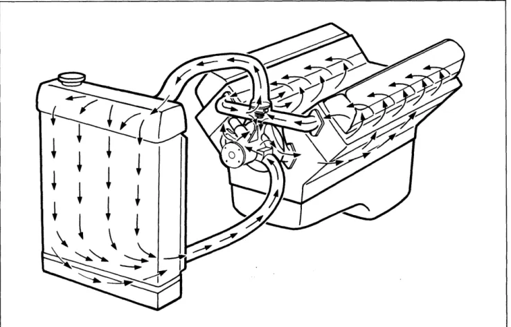
A die cast aluminum water pump is centrally mounted on the front of the engine front cover. It is driven by "V" belts, which also drive the generator, power steering pump, and refrigerant compressor on Air Conditioned cars. Coolant is drawn from the bottom of the radiator and de livered to both cylinder banks at the same time. The coolant circulates around the cylinders and up through drilled holes to the cylinder heads. After circulating through the heads, it flows to the thermostat housing, located at the top of the cylinder head water outlet pipe, Fig. 11-1.
When the thermostat is closed, coolant from the cylinder heads is drawn through a by-pass passage in the cylinder head water outlet pipe to the water pump and recirculated. When the engine is sufficiently warm, the thermostat will open and coolant will flow to the upper radiator tank, where it is cooled as it circulates down through the radiator core, completing the cycle.
A thermostatically controlled clutch is used in conjunction with a five-bladed fan on Air Con ditioned cars. The clutch is designed with an internal bi-metal control valve which makes the clutch sensitive to engine speed and under hood air temperature. With this design, engine cool ing is improved and fan noise is reduced at low car speeds.
When car speed is below 70 MPH, the clutch is disengaged sufficiently to control fan noise while providing adequate fan speed. The large diameter and greater pitch five-bladed fan will provide improved engine cooling even though the fan is running at reduced speeds. When car speed is above 70 MPH the clutch will engage to provide adequate fan speed for engine cooling.
The water pump is serviced only as an assem bly. The thermostatically controlled clutch, used on Air Conditioned cars, is also serviced only as an assembly.
11-1
SERVICE INFORMATION
1. Radiator Filler Cap Removal
The radiator cap on all 1963 Cadillac cars is of the bayonet type with a safety catch. To re move, place a cloth over the cap and rotate it counterclockwise until the stop is reached. In this position, the cooling system is vented to the atmosphere through the overflow hose. The cap should be left in this safety position until all pres sure or steam has been relieved.
If the coolant boils when the cap is placed in the safety position and steam continues to escape, cool the radiator by flowing cold water over the outside while the engine is idling. The cap may then be removed by pressing down slightly and rotating cap further counterclockwise.
2. Cooling System Preventive
Maintenance
The cooling system should be drained, flushed with water only, and refilled annually with water and an ethylene glycol base anti-freeze to protect the engine to at least -20°F. Inhibitor and sealer should also be added to the system to retard rust and scale, keep water passages open, seal against internal leakage, and to assist in lubricating the water pump.
Retorquing the cylinder head screws, checking all hose connections, and adding inhibitor and sealer should be performed annually, or when ever ethylene glycol base anti-freeze is changed. The cylinder head screws should be torqued to 75 foot-pounds.
These maintenance procedures are necessary to avoid the possibility of external leakage, and of anti-freeze solutions leaking into the engine, or combustion gases blowing into the cooling sys tem. Anti-freeze and water mixed with engine oil will form sludge, which will interfere with lubri cation and, in some cases, may form varnish-like deposits that will cause gumming and sticking of moving parts.
Check coolant level at each engine oil change. Maintain coolant level 1/2 inch to 1 inch above cooling tubes in top of upper radiator tank when the coolant is cold.
3. Testing Anti-Freeze Solutions
A hydrometer test will indicate whether anti freeze or water, or both, should be added to bring the coolant to its proper level and to maintain the desired freezing point of the solution.
Some devices used for testing anti-freeze solu tions will indicate the correct freezing point only
when tested at a specific temperature. Other testers, provided with thermometers and tables, indicate freezing points corresponding to readings made at various temperatures. Disregarding the
temperature of the solution when testing may cause an error as large as 30°F in determining the freezing point.
4. Radiator and Cap Leak Check
The cooling system pressure should be checked whenever cases of overheating, coolant loss, or anti-freeze odors are reported. Any one of the common types of cooling system testers will prove helpful in testing the cooling system ac
cording to the following procedure: a. Testing Radiator Cap
CAUTION: Avoid removing the radiator cap while the engine is at normal operating temper ature, as hot coolant will spray out. If it is necessary to remove the cap while the engine is hot, rotate the cap slowly counterclockwise until the first stop is reached, and allow pres sure to escape. Then turn it further counter clockwise to remove.
1. Remove radiator cap.
2. Wet cap gasket with water and wash away sediment, if any, then install cap on tester.
3. Build up pressure to cap capacity. The tester should read within 13- 1/2 to 16- 1/2 psi for all series cars.
4. The cap should hold the pressure within these limits for approximately 10 seconds. A cap that does not meet these requirements should be replaced.
b. Testing Cooling System
1. Tighten all cylinder head screws to 75 foot-pounds.
2. Tighten all hose connections. 3. Fill radiator to normal level.
4. Install tester in radiator neck, following in structions supplied with tester.
5. Build pressure up to 15 psi.
6. Watch the gage for any drop in pressure. A pressure drop will indicate a leak.
A pressure tester can also be used effectively to test for leaks after components of the cooling system have been serviced or replaced.
ENGINE COOLING
11-35.
Radiator Thermostat Test
7. Fill system with fresh water and operate engine to normal operating temperature to make The radiator thermostat may be checked by sure system is full.suspending it, with the thermostat heat control
unit down, in a small pan of water containing a
8.
Thermostat
thermometer. Neither the thermostat nor the
Removal and Installation
thermometer should rest on the bottom of the panbecause of the uneven concentration of heat at
a. Removal
this point when the pan is heated. The thermostat
valve should start to open at a temperature be- 1. Drain radiator until coolant level is below tween 172°F and 177°F. When the water reaches level of thermostat housing.
a temperature of 198°F, the valve should be fully
open approximately 1/2 inch. 2. Disconnect upper radiator hose at thermo stat housing.
6. Flow Test for Radiator Clogging
3. Remove two cap screws that hold thermostat A quick check for a restricted radiator may be housing to cylinder head water outlet pipe and made by removing the radiator cap and running remove housing. Discard gasket.
the engine until it is above normal operating tem
perature. When the engine speed is increased 4. Remove thermostat from top of cylinder from idle to 2000 RPM, the coolant level in the head water outlet pipe.
upper radiator tank should not rise noticeably.
If the level rises or coolant overflows from the b.
Installation
filler neck when the speed is increased, it indi cates a restricted radiator.
1. Install thermostat in opening at top of cyl inder head water outlet pipe, with valve up.
7. Cooling System Flushing Procedure
2. Position a new thermostat housing gasket 1. Drain coolant from cooling system by open- coated with gasket cement on water outlet pipe. ing radiator drain cock and removing two drain
plugs from cylinder block. 3. Install thermostat housing on water outlet pipe and secure with two attaching screws. 2. After the drain points have been closed, re- Tighten screws to 10 foot-pounds.
fill system with fresh water only, install radiator
cap, and set heater and defroster levers to maxi- 4. Connect upper radiator hose on thermostat mum heat position. This opens the water control housing.
valve and allows the water to pass through the
heater core. 5. Fill cooling system to proper level.
Add NOTE: On Seventy-Five series cars, the anti-freeze if necessary.
rear heater should also be set at the maximum
heat position,
9. Radiator Assembly
Removal and Installation
3. Run engine at medium speed for one hour at
a temperature as hot as possible without boiling, a.
Removal Non-Air Conditioned Cars
Cover radiator if necessary.1. Drain coolant from radiator. 4. Inspect the following points in the cooling
system:
2. Disconnect upper radiator hose at thermo stat housing and lower radiator hose at water
a, Radiator core for leaks. pump.
b. Radiator air passages for plugging caused
3. Disconnect two transmission cooler lines by bugs, leaves, etc.
from rear of radiator at lower tank, and plug ends of lines to prevent loss of transmission fluid. c. Condition and tension of drive belts.
4, Remove the two top radiator to cradle d. Condition of hoses and tightness of damps, clamps. It is not necessary
to remove lower clamps.
5. Drain system by opening all drains.
5. Remove radiator by lifting straight up. 6. After the drain points have been closed, add
the required amount of ethylene glycol base anti
freeze to protect engine to at least -20°F. Also b. Installation Non-Air Conditioned Cars use inhibitor and sealer, regardless of whether
2. Install the two top radiator to cradle clamps. 3. Connect the two transmission cooler lines at lower rear of radiator.
4. Connect upper and lower radiator hoses, 5. Fill cooling system, adding anti-freeze if necessary. Also add inhibitor and sealer.
6. Run engine sufficiently to pump coolant through entire system and check radiator and transmission fluid levels.
7. Check cooling system and transmission cooler lines for leaks.
c. Removal Air Conditioned Cars
1, Drain coolant from radiator.
2. Disconnect upper radiator hose at thermo stat housing and lower radiator hose at water pump.
3. Disconnect two transmission cooler lines from rear of radiator at lower tank, and plug ends of lines to prevent loss of transmission fluId,
4. Remove the two bottom and top cradle to shroud clamps. This will allow shroud to be pushed away from radiator.
5. Remove radiator by lifting straight up.
d. Installation Air Conditioned Cars
1. Place radiator in position.
2. Move shroud into place and connect the two bottom and two top cradle to shroud clamp.
3. Connect two transmission cooler lines at lower rear of radiator.
4. Connect upper and lower radiator hoses, 5. Fill cooling system, adding anti-freeze if necessary. Also add inhibitor and sealer.
6. Run engine sufficiently to pump coolant through entire system and check radiator and transmission fluid levels.
7. Check cooling system and transmission cooler lines for leaks.
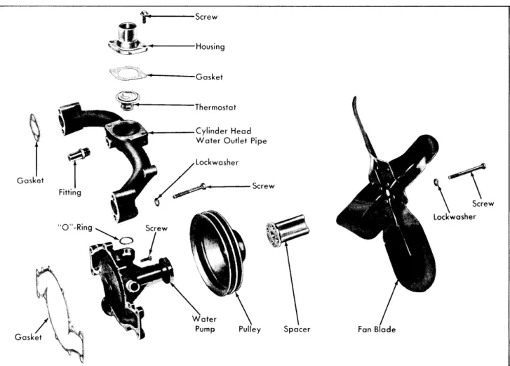
Screw
Housing
J--- -Gasket
Gasket
Screw Lockwasher
Gask
Spacer Fan Blade
/
ENGINE COOLING
10. Water Pump
Removal and Installation
Non-Air Conditioned Cars
Fig. 11-2
a. Removal
1. Disconnect positive battery cable. 2. Drain coolant from radiator.
3. Loosen four cap screws that hold fan blade assembly to water pump.
4. Loosen power steering pump belt and gen erator belt.
5. Remove four cap screws that hold fan blade assembly to water pump and remove fan blade and spacer.
6. Remove power steering pump belt, generator belt, and pulley.
7. Remove two cap screws that hold gene:rator support bracket to cylinder head water outlet pipe and position generator and support bracket away from engine.
8. Remove three cap screws that hold oil filter assembly to oil filter support bracket and remove oil filter assembly. Discard gasket.
9. Remove three cap screws that hold oil filter support bracket to engine front cover and remove support bracket, Discard gasket.
10. Disconnect upper radiator hose at thermo stat housing and lower radiator hose at water pump.
11. Disconnect heater inlet hose at cylinder head water outlet pipe and heater outlet hose at
water pump.
12, Remove three remaining cap screws that hold cylinder head water outlet pipe to cylinder heads and remove water outlet pipe. Iiscard flange surface gaskets and 0-ring seal from neck of water outlet pipe.
Remove ten remaining cap screws that hold pump to engine front cover and cylinder and remove water pump, Fig. 11-3. Dis
b. Installation
1. Install new pump gasket over locating dowels on engine front cover.
2. Install water pump on engine front cover, lining up dowel holes in pump with locating dowels on front cover and loosely install ten attaching screws, Fig. 11-3,
3. Install oil filter support bracket on engine front cover, using new gasket, and secure with
13. water block, card gasket.
Key Size Torque
A B C D -1/4-20x1-1/4 5/16-18x3-1/4 3/8-l.6x3-5/8 3/8-16x3-7/8 5 foot-pounds 10 foot-pounds 15 foot-pounds 15 foot-pounds
Fig. 11-3 Water Pump Attaching Screws
three attaching screws. Tighten the two lower screws to 10 foot-pounds.
4. Tighten all water pump attaching screws to the proper torque specifications as shown in Fig. 11-3,
5. Lubricate new water outlet pipe to water pump 0-ring seal with silicone, and install 0-ring in pump body against shoulder in bore.
6. Brush gasket cement on water outlet pipe flange surfaces and place new flange gaskets on water outlet pipe.
7, Install neck of water outlet pipe in bore in pump body, and position flange surfaces against cylinder heads. Secure with three of the four attaching screws. Tighten screws to 20 foot-pounds.
8. Install oil filter assembly on oil filter sup port bracket, using new gasket, and secure with
three attaching screws. Tighten screws to 15 foot-pounds.
NOTE: If oil pump gears were removed from engine front cover for service, fill oil passages in support bracket with engine oil before installing oil filter assembly. This will enable oil pump to prime itself when engine is started.
9. Install generator support bracket on cylin der head water outlet pipe and secure with two attaching screws. Tighten screws to 20 foot-pounds.
10. Connect lower radiator hose and heater outlet hose to water pump.
11-5
housing, and heater inlet hose to cylinder head 13. Disconnect heater inlet hose at cylinder water outlet pipe. head water outlet pipe and heater outlet hose at
water pump. 12. Install pulley, spacer, and fan blade on
water pump and secure with four attaching screws, 14. Remove four cap screws that hold cylinder Tighten screws to 18 foot-pounds. head water outlet pipe to cylinder heads and re
move water outlet pipe. Discard flange surface 13. Install generator belt and adjust as de- gaskets and 0-ring seal from neck of water out scribed in Section 12, Note 39. let pipe.
14. Install power steering pump belt and adjust 15. Remove ten remaining cap screws that hold as described in Section 5, Note 3. water pump to engine front cover and cylinder block, and remove water pump, Fig. 11-3. Dis 15. Connect positive battery cable, card gasket.
16. Fill cooling system, adding anti-freeze if
b. Installation
necessary. Also add inhibitor arid sealer.
1. Install new pump gasket over locating dowels 17. Operate engine to normal operating tern- on engine front cover.
perature to make sure system is full, and check
for leaks at all connections. 2. Install water pump on engine front cover, lining up dowel holes in pump with locating dowels
1 ‘1. Water Pump
on front cover, and loosely install ten attachingRemoval and Installation
screws, Fig. 11-3.Air Conditioned Cars
3. Install oil filter support bracket on engine a.
Removal
front cover, using new gasket, and secure withthree attaching screws. Tighten the two lower 1. Disconnect positive battery cable, screws to 10 foot-pounds.
2. Remove carburetor air cleaner. 4. Tighten all water pump attaching screws to the proper torque specifications as shown in Fig. 3. Drain coolant from radiator. 11-3.
4. Loosen four cap screws that hold fan blade 5. Lubricate new water outlet pipe to water and clutch assembly to water pump. pump 0-ring seal with silicone, and install 0-ring
in pump body against shoulder in bore. 5. Partially remove refrigerant compressor as
described in Section 13, Note 29a. 6. Brush gasket cement on water outlet pipe flange surfaces and place new flange gaskets on 6. Loosen power steering pump belt and gen- water outlet pipe.
erator belt.
7. Install neck of water outlet pipe in bore in 7. Remove four cap screws that hold fan shroud pump body and position flange surfaces against to radiator and position fan shroud away from cylinder heads. Secure with four attaching screws.
radiator. Tighten screws to 20 foot-pounds.
8, Remove four cap screws that hold fan blade 8. Install oil filter assembly on oil filter sup-and clutch assembly to water pump sup-and remove port bracket, using new gasket, and secure with fan blade and clutch assembly. Removefanshroud. three attaching screws. Tighten screws to 15
foot-pounds. 9. Remove compressor belt, power steering
pump belt, generator belt, and pulley, NOTE: If oil pump gears were removed from engine front cover for service, fill oil 10. Remove three cap screws that hold oil passages in support bracket with engine oil filter assembly to oil filter support bracket and before installing oil filter assembly. This will remove oil filter assembly. Discard gasket. enable oil pump to prime itself when engine is
started.
11. Remove three cap screws that hold oil
filter support bracket to engine front cover and 9. Position fan shroud between engine and remove support bracket. Discard gasket. radiator.
12, Disconnect upper radiator hose at thermo- 10. Install pulley and fan blade and clutch as-stat housing and lower radiator hose at water sembly on water pump and secure with four at taching’ screws, Tighten screws to 26 foot-pounds. pump.
ENGINE COOLING
11-711. Install fan shroud on radiator and secure 2. Remove two top cap screws that hold fan with four attaching screws, shroud to radiator and position fan shroud away
from radiator. 12. Install refrigerant compressor as described
in Section 13, Note 29b. 3. Remove four cap screws that hold fan blade and clutch assembly to pulley and remove fan 13. Install generator belt and adjust as de- blade and clutch assembly.
cribed in Section 12, Note 39.
14. Install power steering pump belt and adjust 4. Remove four cap screws that hold clutch as described in Section 5 Note 3 assembly to fan blade and remove clutch from
fan blade. 15, Install compressor belt and adjust as de
scribed in Section 13, Note 30.
b. Installation
16, Install carburetor air cleaner.
- 1. Install clutch assembly on fan blade and
17. Connect positive battery cable.
secure with four attaching screws. Tighten screws to 16 foot-pounds.
18. Fill cooling system, adding anti-freeze if
necessary. Also add inhibitor and sealer.
19. Operate engine to normal operating temper- 2. Position fan and clutch assembly on pulley ature to make sure system is full, and check for and secure with four attaching screws. Tighten leaks at all connections, screws to 26 foot-pounds.
12. Fan Blade and Clutch Assembly
Removal and Installation
3. Position fan shroud against radiator andAir
Conditioned Cars
secure with two top attaching screws.a. Removal
1. Loosen refrigerant compressor belt adjust- 4. Install and adjust compressor belt as de ing bolts and remove belt from compressor pulley. scribed in Section 13, Note 30.
DIAGNOSIS CHART
CONDITION
CAUSE
REMEDY
Engine Overheats Loss of coolant. Belt tension incorrect. Radiator fins obstructed. Thermostat defective. Cooling system passages blocked by rust or scale, Water pump inoperative. Spark timing too far retarded.
Refer to Loss of Coolant. Adjust belts.
Clean away bugs, leaves, etc. Install new thermostat.
Flush cooling system - add
anti-freeze, inhibitor and sealer, and water.
Replace water pump. Correct spark timing. Engine Fails to Reach Normal
Operating Temperature
Thermostat inoperative or of incorrect heat range.
Temperature sending unit de-fective causing gage to indi cate low engine temperature. Temperature gage defective not indicating true engine tem perature.
Install correct thermostat. Replace sending unit.
DIAGNOSIS CHART Cont’d.
CONDITION
CAUSE
REMEDY
Loss of Coolant Leaking radiator. Repair
Loose or damaged hose con- Reseat or replace hoses or
nections. clamps.
Water pump leaking. Replace water pump. Cylinder head gasket leaking. Replace gasket.
Improper cylinder head screw Torque screws to 75
foot-torque. pounds.
Cylinder block core plugs Resurface or replace. leaking.
Cracked cylinder head or block Resurface or replace. or warped cylinder head or
block gasket surface.
Radiator cap or sealing sur- Repair or replace. face defective.
SPECIFICATIONS
All Series
All Series
Item
Unless Other-
Item
Unless Other
wise Noted
wise Noted
BELTS RADIATOR
Type Wedge Capacity of system with Heater
Width .380" Non-Air Conditioned Cars 17-1/4 qts.
Length Air Conditioned Cars 18-1/4 qts.
Generator Non-Air Conditioned Cars . 53.10" 75 Series only
Generator Air Conditioned Cars . . . 52.40" Non-Air Conditioned Cars . . . . 19-3/4 qts.
Power Steering Pump 50.62’ Air Conditioned Cars 20-3/4 qts.
Compressor 57.46" ,
Capacity of system without heater
Tension and Air Conditioning 16-1/4 qts.
Used 70 lbs.
New 100 lbs.
‘
Area of core 438 sq. in.
FAN Core Depth
Non-Air Conditioned Cars 1-1/4"
Drive Ratio Air Conditioned Cars 2.0"
Non-Air Conditioned Cars 96 to 1.0
.
Air Conditioned Cars 1.1 to 1.0 Core Center Constant, ,
-Non-Air Conditioned Cars 18
Number of Blades Air Conditioned Cars 20
Non-Air Conditioned Cars 4 Tubing Spacing 55
Air Conditioned Cars 5
HOSES Radiator Cap Pressure 13-1/2 to
.
Hose, thermostat housing to 16-1/2 psi
Diameter, inside 1-1/2" THERMOSTAT
Type Molded
Starts to open 172 F to 177 F
Hose, radiator to water pump Bottom
Diameter, inside 1-3/4" Fully open
ENGINE COOLING
11-9TORQUE SPECIFICATIONS
Material
Number
A
ica ion
,ize
Pounds
Foot
280M 300M Special
260M 1010 280M 260M 260M 260M 260M
Clutch to Fan Screw Cylinder Head Screw
Fan Blade Assembly Mounting Screw A/C Fan Blade Assembly Mounting Screw Non A/C Heater Hose Clamp
Thermostat Housing Screw
*Water Pump to Cylinder Block Screw *Water Pump to Cylinder Block Screw *Water Pump to Front Cover Screw
Water Outlet Pipe to Cylinder Head Screw *Refer to Fig. 11-3, for proper screw location.
5/16-18 7/16-14 5/16-24 5/16-24 10-24 5/16-18 3/8-16 5/16-18 1/4-20 3/8-16
16 75 26 18 14 in. lbs.
10 15 10 5 20
COUPE DE 6357