Sharif University of Technology
Scientia IranicaTransactions B: Mechanical Engineering www.scientiairanica.com
A novel computational model of stereo depth
estimation for robotic vision systems
K.-Y. Chen
, Ch.-H. Chen and Ch.-Ch. Chien
Department of Mechanical Engineering, Chung Yuan Christian University, 200, Chungpei Rd., Chungli District, Taoyuan City, 32023, Taiwan, R.O.C.
Received 22 May 2014; received in revised form 4 May 2015; accepted 15 September 2015
KEYWORDS Stereovision;
Variable focal length; Robotic vision; Ane deformation; Non-uniform spacing.
Abstract.This paper presents a novel computational model of stereovision for improving the accuracy of three-dimensional data extracted from a stereo-pair image with no eect of changes in focal length. For decades, most previous studies on stereovision have focused on the establishment of stereo matching, and have made conclusions on the premise of a xed focus. In general, error in the depth estimate becomes bigger when the focus and aperture are unknown or not xed. For that reason, a three-stage framework is proposed in this paper to modify the conventional stereovision model for improving the accuracy of depth estimation. The rst stage is to modify the computational model of conventional stereovision for varifocal cameras. Then, the spacing of depth intervals in the non-uniform spacing of discrete depth levels can be altered, in particular, to be unaected by changes in focal length. Finally, by considering the ane transformation, we add the deformation coecient into the modied stereovision model for correcting three-dimensional ane deformations. Experimental results demonstrated that the depth estimation from stereo images using the proposed scheme was more accurate than conventional methods. The percentage error of most estimates fell between 0.06%-0.82%, and the error value increased from 0.02 cm to 2.21 cm within 6 m.
© 2015 Sharif University of Technology. All rights reserved.
1. Introduction
Extracting 3D data from a pair of stereo images is called binocular vision or stereovision, and has been studied by researchers for decades. The common binoc-ular vision model uses two cameras placed in parallel to imitate the distance and depth-perception abilities of the human visual system. In general, depth informa-tion can be used to reproduce an object's 3D structure in a scene, track moving objects for visual navigation, or measure distance information for optical inspection
*. Corresponding author. Tel.: +886-3-2654322; Fax: +886-3-2654399
E-mail addresses: [email protected] (K.-Y. Chen); [email protected] (Ch.-H. Chen); ccash [email protected] (Ch.-Ch. Chien)
systems [1,2]. The basic principle of stereovision is to determine the distance between object and camera using the positions of the object in the left and right images, simultaneously, and their geometrical relation-ship. There are two major problems of a stereovision model: 3D reconstruction and stereo matching. Over the past few decades, a number of dierent approaches have been proposed in the literature for solving these problems. Marr and Poggio [3] rstly analyzed the computational model of the stereo-disparity problem and proposed a cooperative algorithm to implement the computation of disparity information from a pair of stereo images. Barnard and Fischler [4] reviewed various computational stereo techniques and provided a representative sampling of computational stereo re-search. After reviewing advances in computational stereo from roughly the early 1990s to the early 2000s,
Brown et al. [5] focused primarily on three topics: correspondence techniques, methods for occlusion, and real-time implementations. However, many real-time stereovision applications, such as visual serving, visual navigation, and obstacle avoidance, do not necessarily need to extract accurate depth information. Therefore, several studies developed some active vision schemes for computing the relative depth of points in a pair of stereo images with no camera calibration or prior knowledge of the parameters of the stereovision system required [6,7]. Besides, because color images can provide more information than grey-level images, con-siderable research work has been done to oer various methods for matching color images [8].
As mentioned above, most studies in stereovision have focused on the establishment of stereo matching and all have assumed that the focal length of the lens is constant. However, varifocal lens systems have become more commonly available in recent years for mobile phones, digital cameras, and machine vision applications. Sengupta [9] analyzed the eects of unequal focal lengths, and derived the equations of modied epipolar lines. Furthermore, several studies have reported dealing with the design problem of the operation mechanism and eects of image acquisition with an extended depth of eld for variable-focus liquid lenses [10].
There is an important issue in stereovision using varifocal cameras that should be noticed. If the focal length of the lens is not constant or exactly known, errors of depth estimation based on the conventional stereovision model will increase. More recently, a modied stereovision model without a focus factor has
been proposed to replace conventional stereovision [11]. This modied stereovision model can decrease the error of depth estimation about one half compared with the conventional stereovision model, but only for the range of 2 m. In this paper, we propose further amendments to improve the depth estimation accuracy by expanding the scope of the application in two steps. First, due to inadequate camera resolution, object baselines with smaller depth dierence vanish, and this seriously restricts the depth resolution. In this case, non-uniform spacing of the discrete depth level increases sharply with an increase in depth and distance. Second, when non-Euclidean geometric space, consisting of digital images, is used to inversely estimate scaling and ane space warping in ane space along the direction of the Z axis, the magnied eect of the non-uniform discrete depth level is not the uniform magnication of the square pixel in a scale of 1:1. We use the ane space warping coecient to correct the above drawback.
The remainder of this paper is organized as follows. Section 2 briey reviews the fundamentals of conventional and modied stereovision models. Sec-tion 3 presents the proposed correcSec-tion equaSec-tions of the modied stereovision without the focus factor. Experi-mental results of the proposed scheme are presented in Section 4. Finally, conclusions are given in Section 5.
2. Stereovision model
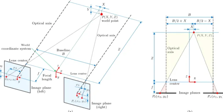
2.1. The conventional stereovision model The conventional stereovision grabs a pair of images simultaneously using two horizontally placed cameras, as shown in Figure 1. Here, we assume that the
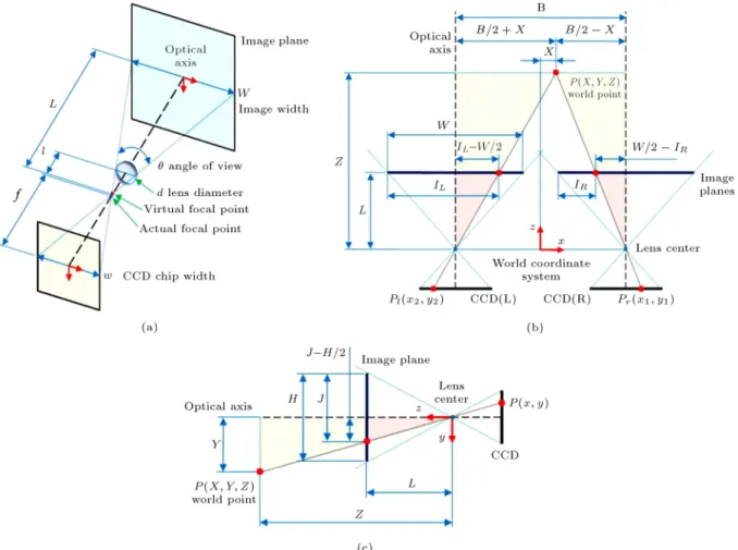
Figure 2. The modication of stereovision model: (a) CCD imaging; (b) top view; and (c) right view.
corresponding points in two images are identied, and the parameters of two cameras are known. Then, the geometry of stereovision can be simplied as a triangulation. In Figure 1, the objective of stereovision is to nd the coordinates (X; Y; Z) of the world point, P , having corresponding points (x1; y1) and (x2; y2) in
left and right images, respectively [12]. This is easily done using similar triangles, that is:
B 2 X
x1 = B 2 + X
x2 =
Y y1 =
Y y2 =
Z
f; (1) where f is the focal length, and B, called the baseline, is the distance between the centers of the two lenses. The world coordinates (X; Y; Z) may be computed as follows:
X = B2
x1+ x2
x2 x1
; Y = xBy1
1 x2 =
By2
x1 x2;
and Z = xBf
1 x2: (2)
Eq. (2) indicates that if baseline B and focal length f are known, and the corresponding image coordinates (x1; y1) and (x2; y2) can be determined, computing the
coordinates (X; Y; Z) of P is a simple matter.
2.2. The modied stereovision model
In general, an important problem in variable focus stereovision is that the focal length of the lens may not be actually constant. For this reason, using Eq. (2) will reduce the accuracy of depth dimen-sion [13,14]. Chen et al. [11] proposed a modied stereovision model for improving the accuracy of depth estimation from a pair of stereo images, especially suitable for varifocal cameras, as shown in Figure 2. Two cameras are separated by a distance, B, in the x-direction, and both optical axes are parallel. For convenience, the coordinate system centered be-tween two cameras is called the world coordinate system.
As shown in Figure 2(a), distance L (in centime-ters) between the image plane and the virtual focal point can be easily measured using a simple camera calibration procedure as follows. First, by measuring diameter, d, and the angle of view, , of the lens, the distance, l, between the lens and the virtual focal point can be obtained. Second, if an arbitrary image plane is in front of the camera and its location is known, the width of the captured image can be measured. From the similar triangles of imaging, as shown in Figure 2(b) and (c), Eq. (1) becomes as follows:
B 2 X W
2 IR
= B2 + X
IL W2 =
Y J H
2
= ZL; (3)
where IL and IR are the horizontal positions, and J is
the vertical position of the object in the two images (in pixels), W and H are the image width and height (in centimeters), respectively. In Eq. (3), only the units of IL, IR, and J are in pixels. Here, assume that the
image resolution is M N (in pixels). After converting pixels to centimeters, Eq. (3) can be expressed as:
B 2 X W
2 IRWM
= B2 + X
ILWM W2 =
Y JH
N H2
= Z
L: (4) Then, the world coordinates (X; Y; Z) may be com-puted as follows:
X = B(IL+ IR M)
2(IL IR) ; Y =
BMH(2J N) 2NW (IL IR);
Z = W (IBLM
L IR): (5)
Compared with Eq. (2), the term focal length, f, does not appear in Eq. (5). Note that all coordinates obtained with Eq. (5) are with respect to the world coordinate system centered between two cameras.
3. Correction equation of modied stereovision without focus
3.1. Depth error correction of non-uniform discrete depth level
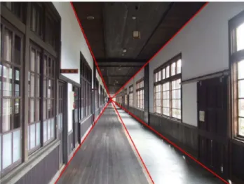
Real space is a description based on Euclidean space, and cannot describe perspective projection. In Eu-clidean space, parallel lines and standard circles are used, but Euclidean space is a tactile, not visual, geometry [15]. As shown in Figure 3, visual geometry has no parallel lines, and all lines near or far may intersect on the vanishing point in space. From visual geometry, the sensing depth of the similar spaces can be estimated. The particle size in the actual image panel is not innitely small, and the pixel is the smallest unit. As for object depth, smaller baselines may seriously restrict achievement of depth resolution. The granularity of pixels caused by the limited resolution of digital images may result in a discrete discernible depth level, and the aected interval may sharply increase with depth and distance.
Based on the non-uniform spacing of the discrete depth level of two parallel cameras, the depth and distance, Z and Z, (spacing of depth interval) can be deduced, based on the relationship between similar triangles [16].
Z = fB Z(Z + Z); (6)
Figure 3. All lines in visual geometry, either near or far, may intersect on vanishing point in the space.
where Z is the sensing depth (mm) from the baseline center point to some point in space; Z is the spacing of depth interval (mm); is the smallest unit of the image (pixel); B is the baseline, namely distance (mm) between the two lens; f is the focal length of the lens, i.e. distance (mm) from pin hole aperture to image plane.
In Eq. (6), when Z is smaller than Z, it can be reduced into:
Z
fBZ2: (7)
In the background environment of the variable focus lens system, the geometric structures of the non-uniform spacing of the discrete depth level of the two parallel cameras with two lenses are shown in Figure 4. In varifocal stereovision, the focal length of the lens can be unxed. Thus, we modied Eqs. (6) and (7) into the correction equations of non-uniform spacing of the discrete depth level without focus. The baseline length is B and the distance between the image plane and the virtual focal point is L,. Thus, the depth and distance Z and Z (spacing of depth interval) can be deduced
Figure 4. Non-uniform spacing of discrete depth level of variable focus lens system.
based on the relationship between similar triangles.
Z = WM
LBZ(Z + Z) = W
LBMZ(Z + Z); (8) where W and H are width and height (mm) of images, respectively; M N represents image pixel.
When Z is smaller than Z, Eq. (8) can be reduced into:
Z W
LBMZ2: (9)
The above Z is called the correction equation of the non-uniform spacing of the discrete depth level without focus, and Z + Z is the result corrected by the modied stereovision algorithm. The corrected algorithm can be expressed as:
X = B(IL+ IR M) 2(IL IR) ;
Y =BMH(2J H) 2NW (IL IR); and
Z = W (IBLM
L IR)+
W LBM
BLM W (IL IR)
2
: (10)
The error correction equations of the non-uniform spacing of the discrete depth level without focus are an ideal error correction method. The theoretical basis is a normal view perspective and a single-point
perspective. In cases of other perspectives, or two-point or more perspectives, other methods should be used for correction. Besides, the digital image warping characteristics of space geometry changes are not considered. Thus, the second correction is proposed to increase accuracy.
3.2. Depth error correction of ane geometric space distortion
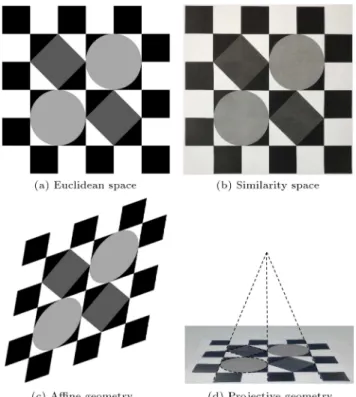
In the machine vision eld, studies on depth estimation often use the imaging principle of nite camera models for perceptive projection to estimate depth. However, we still have to face real world (Euclidean space) and image plane (vision geometry space) transformation problems. Geometric space is displayed in 2D space, as shown in Figure 5, and diagrams of the results, after geometric transformations in visual geometric space, are as shown in Figure 6.
In visual geometry, direct reection, diusion and reection of the light source are mixed. Similarity geometry, ane geometry and projective geometry are included and change at all times and places. Projective transformation can be divided into a combination of three transformations, as follows [15]:
Mp= HsHaHp=
sR t
0T 1 0K 0T 1 vIT 0k
=
A t vT k
; (11)
where R is a rotation matrix; t is a translation matrix;
Figure 6. Diagrams of visual geometric space.
A is a non-singular matrix, and the given value is A = sRK+tvT, which represents the scaling and rotational
deformation state; K is an upper-triangular matrix and det(K)=1 after normalization; vT is a 3 1 vector
matrix, which represents that scaling and rotational deformation is extended at innity; k is a homogeneous scale value, corresponding to the generated matrix model; Hsis the similarity transformation matrix; Ha
is the ane transformation matrix with an increase in ane geometry; HsHa is the ane transformation
with an increase in ane geometric factors; Hp is the
projection transformation matrix with an increase in projective geometric factors.
Digital image distortion is used to estimate the scaling and ane space warp on ane space along the direction of the Z axis, because the ane transfor-mation matrix can be expressed as follows when no coordinate transformation occurs:
Ma = HsHa=
A 0 0T 1
: (12)
The geometric eect of the ane transformation of linear component A involves two fundamental transfor-mations, namely, rotational and non-isotropic scaling. Generally, the equivalent synthetic vision of the area-of-interest of the stereovision system is centered. Thus, only extrusion deformation, scaling and the rotation of the Z axis are considered, as shown in Figure 7. The ane matrix, A, can be decomposed using singular value decomposition.
Figure 7. Eects of two ane deformations on image plane.
Figure 8. Extrusion deformation eect of Z axis towards the direction of Z axis may cause deformation of Y axis.
A=UDVT=(UVT)(VDVT)=R()R( )DR();
(13) where R() represents rotation of the Z axis, R() rep-resents space extrusion deformation caused by rotation of the Z axis, and D is a diagonal matrix, as follows:
D = 2
40 x 0 0y 0 0 0 1 3
5 ; (14)
where x represents the scaling and deformation rate
of the X axis, and y represents the scaling and
deformation rate of the Y axis.
As shown in Figure 8, in ane geometric space, the extrusion deformation eect of the Z axis on the direction of the Z axis may cause deformation in the direction of the Y axis. A circle may be deformed into a scaled elliptical shape; it is stretched longer and longer when it moves toward the direction of the Z axis, and the stretch will not stop until an elliptical shape disappears in the vision plane. Finally, all the circles vanish at an ane critical point. x is assumed to
have zoom scale, and thus, y is space scaling, and the
extrusion deformation rate (zoom in) of the Z axis is increased. When the scale ratio, x, of 1:1 is proposed
in similarly geometric space, the extrusion deformation rate (zoom in) of Z axis is approximately equal to the
ratio of the minimum to maximum axial lengths of the ellipse:
x y
Minor axis length
Major axis length: (15) Physically, for the smallest unit, , of images, the non-uniform spacing of the discrete depth level is enlarged, not in equal proportion, but in scale ratio, y
x, in
ane space. In consideration of what is viewed by binocular vision, the ane space warping coecient, Warp, represents the ane space warping viewed from
left and right cameras:
Warp= ( x
y)L+ (xy)R
2 ; (16)
where (x
y)L is the deformation rate viewed from the
left camera and (x
y)R is the deformation rate viewed
from the right camera, respectively. Thus, the spacing of depth interval, Z, in correction Eq. (9) of the non-uniform discrete depth level without focus can be rewritten as follows:
Z WarpLBMW Z2: (17)
The above equation is called the correction equation of ane space warping. Thus, the modied stereovision algorithm can be expressed as:
X = B(IL+ IR M) 2(IL IR) ;
Y =BMH(2J2NW (I N)
L IR);
Z = W (IBLM
L IR)+ Warp
W LBM
BLM W (IL IR)
2
: (18)
4. Experimental results
In this paper, we designed the binocular vision system illustrated in Figure 9, and the values of the parameters
Figure 9. The experimental setup of binocular stereovision system.
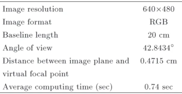
Table 1. Camera parameters of the binocular vision system.
Image resolution 640480
Image format RGB
Baseline length 20 cm
Angle of view 42.8434
Distance between image plane and 0.4715 cm virtual focal point
Average computing time (sec) 0.74 sec
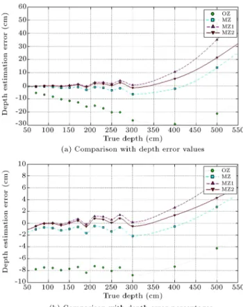
of the system, such as image resolution, image format, baseline length, etc., are shown in Table 1. Two identi-cal CCD cameras are mounted in parallel on a platform with two rotatory degrees of freedom. We applied the proposed stereovision algorithm to calculate the depth of the target centroid in two images, illustrated in Figure 10 and in the ow chart in Figure 11. The stereo images have a size of 640 480 pixels and the distance of the red target with diameter of 4.5 cm is increased from 70 cm to 270 cm with every interval of 20 cm, and then, from 300 cm to 500 cm with every interval of 100 cm. We can obtain the error in the correction equation of the non-uniform spacing of the discrete depth level and the error in the correction equation of the ane space warping, as shown in Tables 2 and 3. Next, we applied four types of stereovision model, respectively, to estimate the depth of the target centroid in two images, as shown in Figure 12, where OZ denotes the estimated depth value (f = 45 mm) in the traditional stereovision algorithm, MZ denotes the estimated depth value in the modied stereovision algorithm, MZ1 represents the estimated depth value obtained from the correction equation of the non-uniform spacing of the discrete depth level, and MZ2 represents the estimated depth value obtained from the correction equation of ane space warping. As a measurement of accuracy of the depth computed using the proposed method in this paper, an error parameter is dened as follows:
error = computed depth actual depthActual depth 100%: (19) In terms of the experiment results, from similarity geometric space to ane geometric space, the percent-age error of the modied binocular vision algorithm in direct estimation of the sensing depth fell between -1.8-0.6%; the error increased from 0.7 cm to the vicinity of 6 cm. The percentage error of the correction equation of the non-uniform spacing of the discrete depth level fell between 0.01-1.43%, and the error increased from 0.01 cm to 3.87 cm. In proximal similarity space, the correction equation of the non-uniform spacing of the discrete depth level is very accurate. However, the ane space domain is not
Figure 10. The stereo image pairs at dierent distances: (a) Captured by left camera; (b) after image processing; (c) captured by right camera; and (d) after image processing.
Figure 11. Process of stereoscopic image processing and depth error correction of ane geometric space distortion.
Figure 12. Comparison of depth estimation errors using four types of stereovision.
accurate. This is consistent with the assumption. The correction equation for the non-uniform spacing of the discrete depth level is an ideal error correction method, but fails to consider digital image deformation by geometric space.
Table 2. Depth calculation and its error in correction equation of non-uniform spacing of discrete depth level. Actual
depth (cm)
Center-of-mass coordinates of
left image
Center-of-mass coordinates of
right image
Computed depth
(cm)
Error (cm)
Error (%)
70.00 (171,368) (131,190) 69.66 -0.34 -0.49%
90.00 (130,336) (144,198) 89.99 -0.01 -0.01%
110.00 (138,325) (151,212) 110.08 0.08 0.07%
130.00 (141,310) (157,214) 129.77 -0.23 -0.17%
150.00 (147,300) (158,217) 150.34 0.34 0.23%
170.00 (150,295) (163,222) 171.22 1.22 0.72%
190.00 (152,290) (165,224) 189.65 -0.35 -0.19%
210.00 (153,286) (167,227) 212.52 2.52 1.20%
230.00 (155,282) (168,228) 232.56 2.56 1.11%
250.00 (156,278) (169,228) 251.53 1.53 0.61%
270.00 (157,278) (171,232) 273.87 3.87 1.43%
300.00 (158,275) (172,233) 300.56 0.56 0.19%
400.00 (161,266) (174,235) 410.57 10.57 2.64%
500.00 (163,264) (177,240) 535.15 35.15 7.03%
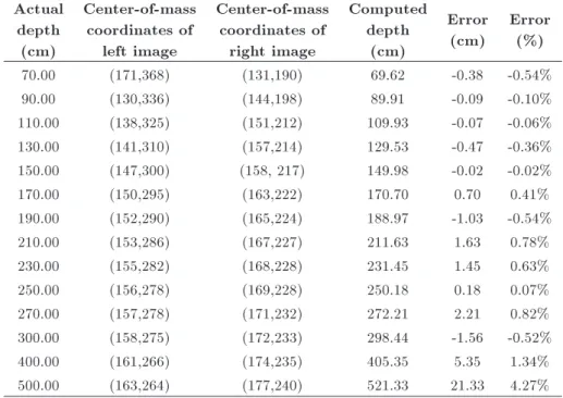
Table 3. Depth calculation and its error in correction equation of ane space warping. Actual
depth (cm)
Center-of-mass coordinates of
left image
Center-of-mass coordinates of
right image
Computed depth
(cm)
Error (cm)
Error (%)
70.00 (171,368) (131,190) 69.62 -0.38 -0.54%
90.00 (130,336) (144,198) 89.91 -0.09 -0.10%
110.00 (138,325) (151,212) 109.93 -0.07 -0.06%
130.00 (141,310) (157,214) 129.53 -0.47 -0.36%
150.00 (147,300) (158, 217) 149.98 -0.02 -0.02%
170.00 (150,295) (163,222) 170.70 0.70 0.41%
190.00 (152,290) (165,224) 188.97 -1.03 -0.54%
210.00 (153,286) (167,227) 211.63 1.63 0.78%
230.00 (155,282) (168,228) 231.45 1.45 0.63%
250.00 (156,278) (169,228) 250.18 0.18 0.07%
270.00 (157,278) (171,232) 272.21 2.21 0.82%
300.00 (158,275) (172,233) 298.44 -1.56 -0.52%
400.00 (161,266) (174,235) 405.35 5.35 1.34%
500.00 (163,264) (177,240) 521.33 21.33 4.27%
warning is more accurate; the percentage error of most estimates fell between 0.06-0.82%, and the error value increased from 0.02 cm to 2.21 cm. When the proximal ane warping is not apparent, the correction equation for the non-uniform spacing of the discrete depth level on the similarity space domain is slightly better than that of the ane space warping. This is consistent with the assumption, although the dierence is not great. When the ane transformation increases, the correction equation of ane space warping on the ane
space domain is the stereovision algorithm with the highest accuracy so far.
5. Conclusions
In this paper, an ecient and accurate computational model of depth estimation based on a modied stereovi-sion model is presented. The newly created correction equation for the non-uniform spacing of the discrete depth level is used to improve stereovision accuracy in
the similarity space. For the object depth, a smaller baseline may seriously restrict the depth resolution that can be achieved, and non-uniform spacing of the discrete depth level caused by the nite resolution of digital images, sharply increases with an increase in depth and distance. Thus, the correction equation of the non-uniform discrete depth level without focus is used to correct the error. Experimental results show that the proposed computational model has the ability to improve the accuracy of depth estimation. We can nally conclude that a slightly modied computational stereo model can extract the accurate depth informa-tion from a pair of stereo images. Besides, it is more important that this model is especially suitable for use in varifocal cameras.
Acknowledgment
This work was supported by the National Science Council of Taiwan (R.O.C.) under grant number NSC 102-2221-E-033-037.
References
1. Li, Z.N. and Hu, G. \Analysis of disparity gradient based cooperative stereo", IEEE Transactions on Im-age Processing, 5(11), pp. 1493-1506 (1996).
2. Nitzan, D. \Three-dimensional vision structure for robot applications", IEEE Transactions on Pattern Analysis and Machine Intelligence, 10(3), pp. 291-309 (1988).
3. Marr, D. and Poggio, T.A. \Cooperative computation of stereo disparity", Science, 194(4262), pp. 283-287 (1976).
4. Barnard, S.T. and Fischler, M.A. \Computational stereo", Computing Surveys, 14(4), pp. 553-572 (1982).
5. Brown, M.Z., Burschka, D. and Hager, G.D. \Ad-vances in computational stereo", IEEE Transactions on Pattern Analysis and Machine Intelligence, 25(8), pp. 993-1008 (2003).
6. Grosso, E. and Tistarelli, M. \Active/dynamic stereo vision", IEEE Transactions on Pattern Analysis and Machine Intelligence, 17(9), pp. 868-879 (1995).
7. Yau, W.Y. and Wang, H. \Fast relative depth compu-tation for an active stereo vision system", Real-Time Imaging, 5(3), pp. 189-202 (1999).
8. Ansari, M.E., Masmoudi, L. and Bensrhair, A. \A new regions matching for color stereo images", Pattern Recognition Letters, 28(13), pp. 1679-1687 (2007).
9. Sengupta, S. \Eects of unequal focal lengths in stereo imaging", Pattern Recognition Letters, 18(4), pp. 395-400 (1997).
10. Ren, H. and Wu, S.T. \Variable-focus liquid lens", Optics Express, 15(10), pp. 5931-5936 (2007).
11. Chen, K.Y., Chien, C.C. and Tseng, C.T. \Improving the accuracy of depth estimation in binocular vision for robotic applications", Applied Mechanics and Ma-terials, 284-287, pp. 1862-1866 (2013).
12. Gonzalea, R.C. and Woods, R.E., Digital Image Pro-cessing, Addison-Wesley, New York, USA (1992).
13. Hsu, H.K., Application of Stereo-Vision Navigation to the Acquisition of Position and Attitude of MAVs, MS Thesis, Tamkang University, Taiwan (2011).
14. Hsieh, K.Y., A Study on a Service Mobile Robot with Remote Control, MS Thesis, Chung Yuan Christian University, Taiwan (2011).
15. Hartley, R. and Zisserman, A., Multiple View Geome-try in Computer Vision, Cambridge University Press, Cambridge, UK (2006).
16. Scharstein, D. \View synthesis using stereovision", PhD Dissertation, Cornell University, USA (1997).
Biographies
Kuan-Yu Chen received his BS and MS degrees in Mechanical Engineering from Chung Yuan Christian University, Taoyuan, Taiwan, in 1988 and 1995, respec-tively, and his PhD degree in Mechanical Engineering from the National Central University, Taoyuan, Tai-wan, in 2008. He is currently Professor in the faculty of Mechanical Engineering at Chung Yuan Christian University, Taoyuan, Taiwan. His research interests are mainly in the area of machine intelligence, intelligent robotics, and automated optical inspection.
Chien-Hung Chen received his BS degree in Mechan-ical and Mechatronic Engineering from the National Taiwan Ocean University, Keelung, Taiwan, in 2007, and is currently a PhD degree student in Mechani-cal Engineering at Chung Yuan Christian University, Taoyuan, Taiwan. His research interests are mainly in the area of automated optical inspection, stereovision-based computational models, and, more recently, 3D reconstruction from line-scan cameras.
Cheng-Chin Chien received his BS, MS and PhD degrees in Mechanical Engineering from Chung Yuan Christian University, Taoyuan, Taiwan, in 1988, 2005 and 2013, respectively, and is currently senior software consultant at Galaxy Software Corporation, Taipei, Taiwan. His research interests are mainly in the areas of image processing and stereovision-based computa-tional models, including, more recently, industry 4.0, big data implementations and cloud computing.