Sharif University of Technology
Scientia IranicaTransactions A: Civil Engineering www.scientiairanica.com
Research Note
Numerical study on exural strengthening of squat RC
shear wall using FRP laminates
F. Shadan
a;, A. Khaloo
aand P. Shadan
ba. Department of Civil Engineering, Sharif University of Technology, Tehran, Iran.
b. Department of Civil and Environmental Engineering, Amirkabir University of Technology, Tehran, Iran. Received 14 February 2012; received in revised form 12 March 2014; accepted 22 November 2014
KEYWORDS Shear wall; Fibre reinforced polymer; Strengthening; Reinforcement details; Anchorage system.
Abstract. Shear wall has been widely used in RC structures due to its high initial stiness and lateral load capacity. Hence, the behavior and eectiveness of retrotting technique on shear wall are needed to be investigated widely. In this paper, a numerical analysis was performed using LS-DYNA nite element program to predict the behavior of squat RC shear wall strengthened by ber reinforced polymer in exure. The strengthening scheme was conducted by externally bonding vertical layers of FRP on each side of the wall and anchoring them at the wall base with a structural steel angle bolted to the support. Numerical results were validated against experimental data. Then, the inuences of number of FRP layers, anchorage system, percentage of horizontal web reinforcement, percentage of vertical web reinforcement and percentage of vertical reinforcement in the boundary element were investigated. The results showed that the scheme can signicantly improve the behavior of the RC shear wall. In addition, the behavior of strengthened wall and strengthening scheme strongly depend on the amount of web reinforcement which can also change the failure mode.
© 2015 Sharif University of Technology. All rights reserved.
1. Introduction
Based on high initial stiness and lateral load capacity of shear wall, its usage as a common type of lateral load resisting system in RC structures has been increased. Old buildings shear wall which has been designed based on older building codes, in new codes sight do not have enough stiness, ductility and strength. Thus major earthquakes subjected them to severe damages. Hence, the behavior and eectiveness of retrotting technique on shear wall are needed to be investigated widely. Among several available techniques for retrotting
*. Corresponding author. Tel.: +98 21 66164211; Fax: +98 21 66014828
E-mail addresses: f [email protected] (F. Shadan); [email protected] (A. Khaloo); p [email protected] (P. Shadan)
RC structures, Fiber Reinforced Polymer (FRP) is quite eective due to its high strength-weight ratio, high resistance to corrosion, and easy handling and installation [1]. Several researchers have investigated the behavior of RC members retrotted with FRP like beams and columns since 1990 [2-6]. However, application of FRP laminates on RC walls has attracted less attention from researchers.
Lombard performed strengthening of shear walls using carbon ber reinforced polymers externally bonded to the two faces of the wall [7]. Uni-directional carbon bers aligned in the vertical and horizontal di-rection were used to increase the strength and stiness of the wall. Other rehabilitation schemes also have been investigated experimentally and showed that use of FRP in rehabilitation of wall is promising [8-10]. These available experimental studies on retrotting of RC shear walls focused on the eectiveness of the
technique rather than attempting to quantify eects of dierent parameters. For instance, the structural behavior of RC shear walls strongly depends on aspect ratio and reinforcement details which can change fail-ure mode and exural capacity of the wall. Further-more, failure mode has considerable inuence on the eectiveness of strengthening technique with FRP.
In this study, predictions were acquired using LS-DYNA [11] nite element program widely used for nonlinear analysis of structures. The adequacy of the numerical approach is veried by compari-son between numerical results and experimental data tested by Lombard et al. [7]. Then, a numerical investigation was performed to predict the behavior of RC squat shear wall strengthened by ber reinforced polymer. Inuence of a number of FRP layers, an-chorage system, various percentages of horizontal and vertical web reinforcement and vertical reinforcement on boundary elements of the wall were investigated. In addition, eect of these parameters on the hysteretic response characteristics of the strengthened wall, such as strength, ductility, dissipated energy and stiness degradation, was studied.
2. Finite-element modeling
The validity of nite element modelling has been veried by testing against experimental data conducted by Lombard et al. [7]. Primarily, a brief description of experimental setup data reported in [7] and utilized as base information for further parametric studies is prepared.
Two of four reinforced concrete shear wall spec-imens were selected for numerical verication. Each specimen had a rectangular cross section of 100 mm thick, 1500 mm wide and a height of 1795 mm. In addition, they had an aspect ratio of 1.2 classied as squat shear wall [12], and were designed to have sucient shear strength, and failed in a ductile ex-ural manner [7]. The walls were constructed using 40 MPa concrete and 10 mm deformed steel bars (fy=
412 MPa). Details of the test specimen are shown in Figure 1.
One of the selected experimental specimens for checking numerical approach was tested in its original state as a control wall, whereas the other selected spec-imen was strengthened with applying uni-directional carbon ber laminates aligned in vertical and hori-zontal direction to the undamaged as-built wall. The carbon ber laminates had a tensile strength of 3480 MPa, a tensile modulus of 230 GPa and a thickness of 0.11 mm. The strengthened wall had one horizontal and two vertical layers of FRP externally bonded on each face of the wall. Moreover, the vertical layers of FRP were anchored at the wall base with a structural steel angle bolted to the support. Figure 2 shows the
Figure 1. Geometry and reinforcement details for reinforced concrete shear wall specimen [7] (units in mm).
Figure 2. CFRP laminates and anchorage system position on strengthened wall [7] (units in mm).
way of applying carbon ber laminates and anchoring system on strengthened wall. A hydraulic actuator supported by a reaction frame applied the lateral load at the top of the specimen through a horizontal cap beam. Subsequently, the specimens were tested in the in-plane direction in reverse cyclic loading, which is according to a predetermined quasi-static loading sequence.
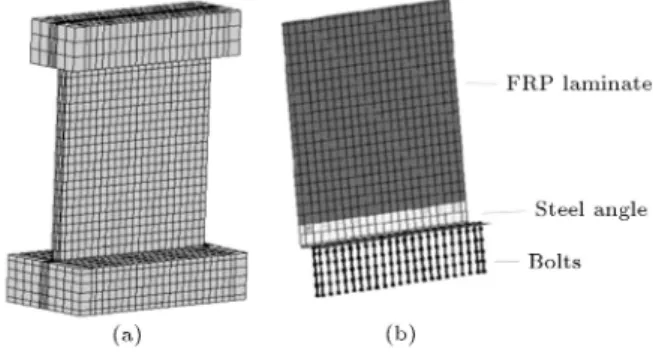
To simulate specimens precisely, almost all details of them were considered. For this purpose, in addition to the concrete wall, the reinforcements and the FRP laminates, the slab beam, the top beam, the angles and the bolts were modeled too. The concrete wall was modeled with eight node solid elements. The reinforced bars and bolts were simulated with two node truss elements. Four node shell elements were used to model the FRP laminates and the steel angles
Figure 3. FE meshes: (a) Concrete wall; and (b) strengthening system.
(Figure 3). Based on the results obtained from other researchers [13], it was decided to use same node at the intersection of the concrete and reinforcements mesh. As a result, they are not able to slip and form a perfect compatibility of strains between concrete and steel. Similarly, studies done by some researchers [14,15] suggest that the nodes link concrete and FRP mesh can be shared. Therefore, a perfect bond was assumed between them too.
The boundary condition contains xed end to the base of the slab beam, and lateral load to the center of the top beam, as the experimental setup which was modeled by considering zero displacement at the bottom surface nods, and nonzero displacement according to predetermined loading.
3. Material constitutive behaviour
Each material data in LS-DYNA program is repre-sented by a number. The program contains several materials models that can be used to represent mate-rials such as concrete, steel and FRP. Material type 84 (MAT WINFRITH CONCRETE model), material type 3 (MAT PLASTIC KINMATIC model) and ma-terial type 22 (MAT COMPOSITE DAMAGE model) were used for modelling the concrete, the steel and the FRP, respectively [11]. Hence, their input material properties and models are just briey discussed. The values used in the input le corresponded to the experimental data.
3.1. Concrete
The WINFRITH concrete model is a basic plasticity model that contains the third stress invariant for treat-ing both triaxial compression and triaxial extension, like Mohr-Coulomb behavior. The plasticity part of this model is based on the shear failure surface pro-posed by Ottosen [16]. This model also includes strain softening in tension with an attempt to regularization via crack opening width, fracture energy and aggregate size. Concrete cracks in tension with up to three orthogonal crack planes per elements. The WINFRITH concrete model is a smeared crack model which through
adjusting the stiness matrix, the eect of crack is considered as described in [11]. In this approach, based on the inputted crack width and aggregate size, this model assumes that the shear can be transferred across the crack. Furthermore, the stress decays as a function of crack width after initiation of tensile crack. This model was developed by Broadhouse and Neilson [17] and Broadhouse [18] over many years and has been validated against experiments [11]. The parameters required by this formulation are as follows.
The uniaxial compressive and tensile strength of the concrete f0
c and ft0 which corresponded to the
experimental data were: f0
c= 40 MPa; (1)
f0
t= 3:4 MPa: (2)
The initial tangent modulus of elasticity of the concrete Ec taken as the value suggested by ACI committee
318 [19] is: Ec= 4700
p f0
c: (3)
The Poisson's ratio of the concrete vc was assumed to
be:
vc= 0:2: (4)
The aggregate size, i.e. max aggregate diameter, is supposed to be 32 mm. The eects of strain rate were not included and the crack width w, at which crack-normal tensile stress goes to zero [11], was taken as:
w = 0:05 mm: (5) 3.2. Steel
The steel bars and steel parts of the specimens were modeled as elastic perfectly plastic material by using the PLASTIC KINEMATIC model, which is provided for modeling isotropic and kinematic hardening plastic-ity as described in [11]. In this approach, the material behaves elastically up to yield stress. Since steel yields, the stress remains at the yield level. The required parameter for this model are yield stress, young's modulus and Poisson's ratio. The yield stress of the steel y used in the specimens was assumed to be:
y = 412 MPa: (6)
The Poisson's ratio of the steel vs was selected as 0.3
and the young's modulus of the steel Esused in analysis
is:
Es= 200 GPa: (7)
3.3. FRP
The Composite Damage model was presented for modeling orthotropic material with brittle failure as
Table 1. Material properties of CFRP used in the analysis. Elastic modulus (GPa) Poisson's ratio Shear modulus (GPa) Shear strength (MPa) Longitudinal tensile strength (MPa) Transverse tensile strength (MPa) Transverse compressive strength (MPa) Thickness (mm) E1 = 230 v21= 0:17 G12= 3:27
E2= 3:034 v31= 0:17 G23= 1:86 700 3480 740 740 0.11
E3= 3:034 v32= 0:3 G31= 3:27
described in [11]. In this study, failure criteria follow the criteria dened by Chang-Chang model [20,21]. In this approach, three failure criteria are considered through using ve material parameters: longitudinal tensile strength, S1, transverse tensile strength, S2,
shear strength, S12, transverse compressive strength,
C2, and nonlinear shear stress parameter, .
The shearing term of a ber matrix, which is the ratio of the shear stress to the shear strength expands each damage mode, is:
=
2 12
2G12 +
3 4124 s2
12
2G12 +
3 4s412
: (8)
The matrix cracking failure criteria, the rst mode, has the following form:
Fmatrix=
2
s2
2
+ ; (9)
when Fmatrix > 1, it is assumed that the failure is
occurred and the material constants of E2, G12, v1and
v2 are set to zero.
The compression failure is the second mode with the failure criteria determined from:
Fcomp=
2 2s12 2 + " c2 2s12 2 1 # 2
c2 + ; (10)
when Fcomp > 1, it is assumed that the failure is
occurred and the material constants of E2, v1 and v2
are set to zero.
The nal mode of failure is caused by ber breakage:
Fber=
1
s1
2
+ : (11)
In this study, the exural strengthening was done by adding CFRP laminates due to its high tensile strength and modulus. The material properties of CFRP used in the analysis are shown in Table 1.
The ber orientation of uni-directional CFRP laminate was determined by material axis option in LS-DYNA program. It is worth noting that FRP has the highest stiness and strength in its ber direction which should be indicated in analysis correctly.
4. Verication of the proposed models
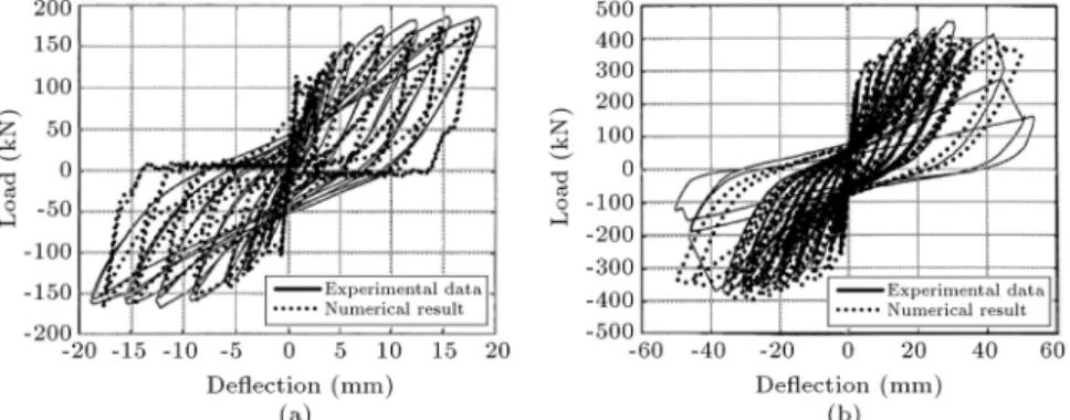
The results of the FE modelling and the experimental data for load versus horizontal deection of the con-trol wall and the strengthened wall are compared in Figure 4. A good agreement is observed between the numerical results and the experimental data.
Hence, the proposed FE model is proved to be able to simulate the behaviour of strengthened RC shear wall with FRP laminates properly.
5. Numerical analysis
In the numerical analysis, the strengthened wall, which is validated against experimental data, was considered. Then, inuence of some parameters such as number
of FRP layers, anchorage system, web reinforcement ratio and various percentages of vertical reinforce-ment in the boundary elereinforce-ments on strengthening with the FRP laminates and behavior of the strengthened RC shear wall was investigated under reversed cyclic load.
5.1. Number of FRP layers
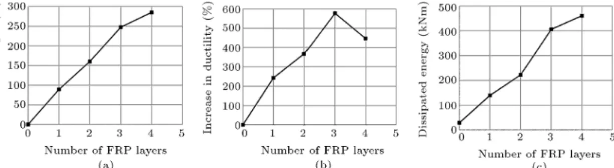
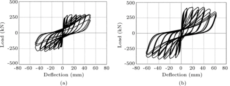
With the purpose of presenting a base for compar-ison, an ordinary reinforced concrete wall without strengthening as Control Wall (CW) was considered. However, other strengthened specimen with increasing number of vertical CFRP layers up to 4 was provided in order to show how FRP changes the control wall behaviour. Figure 5 represents the hysteresis loops of the control wall and the specimen strengthened with one layer of FRP. As can be seen from Figure 5, generally, the strength, the ductility and the dissipated energy of the control wall increased noticeably after strengthening.
Figure 6 shows the envelope curve of cyclic loading versus top deection of the specimens. The SW character stands for strengthened wall and the following numbers represent number of FRP layers. Table 2 presents the details of the control wall and the strengthened walls SW1, SW2, SW3 and SW4. One can observe from the gure that the strength and the ductility of the specimens improved greatly by strengthening and increasing the number of FRP layers. However, adding the fourth layer caused less
Figure 6. Envelope curve of hysteresis loops of specimens CW, SW1, SW2, SW3 and SW4.
increase compared to other layers and further increase in FRP layers numbers seemed to approach no more change.
In order to further study the seismic performance of the specimens, their hysteretic response character-istics, such as strength, ductility, dissipated energy and stiness degradation, is represented. Figure 7(a) and (b) show the increasing of strength and the increasing of ductility versus the number of FRP layers, respectively. Ductility was estimated via calculating displacement ductility factor. It can be seen that strength and ductility approximately increase linearly up to adding the forth layer. However, adding the forth
Figure 5. Comparison of hysteresis loops: (a) Control wall; and (b) strengthened wall with one layer of FRP. Table 2. Details of the control wall and the strengthened walls SW1, SW2, SW3 and SW4.
Specimen Section bw lw
Height hw
Horiz. web reinf.
Vert. web reinf.
Vert. reinf. in boundary elements
Horiz. reinf. in boundary
elements
Number of FRP
layers
(mmmm) (mm) (mm) (mm) (mm) (mm)
CW 100 1500 1795 10@400 10@280 10@280 10@80 0
SW1 100 1500 1795 10@400 10@280 10@280 10@80 1
SW2 100 1500 1795 10@400 10@280 10@280 10@80 2
SW3 100 1500 1795 10@400 10@280 10@280 10@80 3
Figure 7. (a) Increase in strength versus number of FRP layers. (b) Increase in ductility versus number of FRP layers. (c) Dissipated energy versus number of FRP layers.
layer lead to less increase in strength and even decrease in ductility.
Shown in Figure 7(c) is the dissipated energy of specimens calculated by evaluating the area under the hysteresis loops up to the point that peak strength reduces by 20%. It can be seen from Figure 7(c) that the dissipated energy enhanced highly through strengthening, whereas adding the forth layer caused less increase compared to the other layers. The afore-mentioned behaviour which was also seen in strength and ductility of the specimens is because of premature shear failure.
In order to monitoring stiness degradation, the variation of normalized stiness with top horizontal deection is illustrated in Figure 8. The normalized stiness was estimated as the ratio of secant stiness (Ki) and initial secant stiness (K0). It is clear from
Figure 8 that the stiness of CW was signicantly lower than the other specimens. Furthermore, it is observed that CW had considerably severe stiness degradation compared to strengthened specimens. It can be concluded that strengthening has a positive eect on stiness degradation in the post-yielding stage of shear wall deformation. However, increase in the number of FRP layers slightly improves the stiness degradation approach.
Figure 8. Normalized stiness versus deection.
5.2. Anchorage system
Flexural strengthening of the shear wall was provided by FRP laminates, with vertical bers, bonded to the faces of the wall and anchored at the wall base with steel angels bolted to the support. In order to further study the eect of anchorage system on strengthen-ing scheme, the failure modes of FRP peelstrengthen-ing-o at anchorage zone and weak performance of anchorage system was ignored. Additionally, two specimens strengthened with three layers of FRP laminates were considered. Between these two specimens, only one of them strengthened using FRP laminates (SW3P), i.e. without applying anchorage system to serve as a ref-erence for assessing the performance of the anchorage system.
Figure 9 shows the hysteresis loops obtained from numerical analysis of specimens SW3 and SW3P. It is clear from Figure 9 that due to presence of the anchorage system, the damage inicted to strengthened shear wall SW3 was signicantly delayed. Moreover, strength, ductility and dissipated energy of SW3 are substantially enhanced compared to SW3P based on the estimated value reported in Table 3. This enhance-ment in behaviour was due to the anchorage system shear strengthening besides its duty to anchor the FRP laminates. The anchorage system strengthened the base of the shear wall with steel angels in shear which delay the premature shear failure. In addition, it improved the hysteresis loops which increase the dissipated energy. It can be seen that this system of anchorage, i.e. steel angels bolted to support, consider-ably enhances the seismic performance of strengthened shear wall in exure. It is worth pointing out that this improved performance depends on appropriate apply-ing of anchorage system to avoid its weak workapply-ing. 5.3. Horizontal web reinforcement ratio
As reported in [12], diagonal tension failure usually happens when shear wall has insucient shear rein-forcement. The diagonal tension failure has detri-mental eect on ductile behaviour of shear wall. In order to show the eect of insucient horizontal web reinforcement on the hysteresis loops, the percentage of
Figure 9. Hysteresis loops of specimens: (a) SW3; and (b) SW3P.
Figure 10. Comparison of hysteresis loops of strengthened wall with 3 layers of FRP with the horizontal web reinforcement ratio of (a) 0.39%, and (b) 0.25%.
Table 3. Hysteretic response characteristics of SW3 and SW3P.
Specimens Strength (kN)
Displacement ductility
factor
Dissipated energy
SW3P 360 9.2 45.2
SW3 559 35.6 406.5
horizontal web reinforcement in strengthened wall with three layer of FRP was reduced from 0.39% to 0.25%. Comparison of hysteresis loops shown in Figure 10 indicates that horizontal web reinforcement shortage can decrease desired wall behaviour such as strength and ductility.
Specically, to study the inuence of horizontal web reinforcement ratio on wall strengthening, its per-centage in specimens was reduced from 0.39% to 0.25%
and the number of FRP layers was increased from 1 to 3. Table 4 presents the list and details of selected specimens for numerical analysis of the strengthened shear wall with dierent number of FRP layers and various percentage of horizontal web reinforcement.
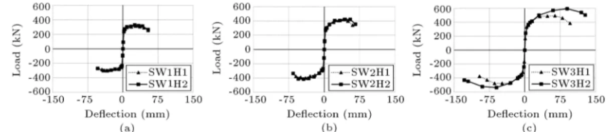
Figure 11 presents the envelope curves of the hysteresis loops obtained from numerical analysis of specimens SW1H1, SW1H2, SW2H1, SW2H2, SW3H1 and SW3H2. To further clarify the eect of the horizontal web reinforcement ratio, the envelope curves of specimens with the same number of FRP layers are shown in one diagram. As can be seen in Figure 11(a) and (b), the reduction of the horizontal reinforcement ratio has little inuence on the envelope curves. How-ever, as shown in Figure 11(c), reducing the horizontal reinforcement ratio leads to signicant changes on the envelope curve of the wall strengthened by 3 FRP layers.
Table 4. Details of the strengthened wall with dierent horizontal web reinforcement ratio. No. Specimen Section
bw lw Height hw h(%)
Horiz. web reinf.
Number of FRP layers
(mm mm) (mm) (mm)
1 SW1H1 100 1500 1795 0.39 10@400 1
2 SW1H2 100 1500 1795 0.25 8@400 1
3 SW2H1 100 1500 1795 0.39 10@400 2
4 SW2H2 100 1500 1795 0.25 8@400 2
5 SW3H1 100 1500 1795 0.39 10@400 3
Figure 11. Envelope curves of the hysteresis loops of specimens SW1H1, SW1H2, SW2H1, SW2H2, SW3H1 and SW3H2.
Figure 12. Strength comparison of specimens SW1H1, SW1H2, SW2H1, SW2H2, SW3H1 and SW3H2.
Figure 12 illustrates the strength of specimens versus the number of FRP layers in which the compar-ison of strength of specimens with the same number of FRP layers is shown close to each other. Based on the column chart, it appears that the reduction of the horizontal reinforcement ratio has little inuence, i.e. less than 3%, on the strength of specimens SW1H1 and SW2H1. However, as can be seen, reducing the horizontal reinforcement ratio of specimen SW3H1 leads to signicant changes on the strength, i.e. av-eragely 15.2%. The main reason is that the failure mode is changed to shear failure. In addition to the strength of the specimen SW3H2, its ductility reduced by averagely 33.3%.
In exural strengthening, avoiding premature
shear failure is essential. Thus, in spite of the anchor-age system assist with the shear strengthening of wall, sucient horizontal shear reinforcement is necessary. It is worth noting that with insucient horizontal shear reinforcement, premature shear failure occurs and the increase in the vertical FRP laminates is useless. 5.4. Vertical web reinforcement ratio
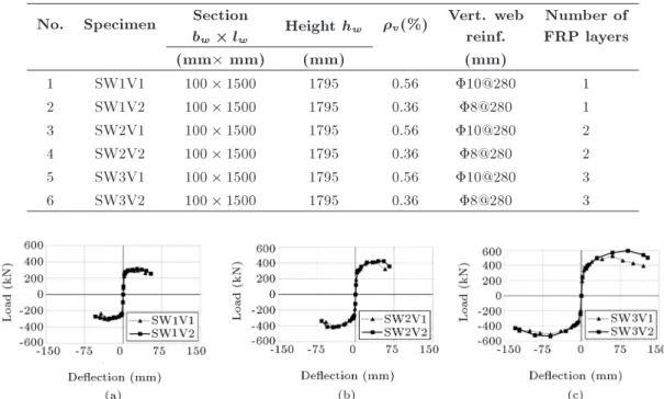
Shear is more important compared to exure in walls with small height to length ratio. Additionally, both horizontal and vertical shear reinforcements are necessary for shear wall. In addition to the dowel action, the vertical reinforcement provides a fastening force to the concrete in the urgent vicinity of the bars, and therefore helps to endure the sliding shear failure [22]. Figure 13 shows the eect of insucient vertical web reinforcement on the hysteresis loops of strengthened wall with three layers of FRP. For this purpose, in Figure 13, a reduction in the percentage of vertical web reinforcement from 0.56% to 0.36% was considered. One can observe from Figure 13 that by decreasing vertical web reinforcement, the strength and the ductility is reduced.
Particularly, to study the inuence of vertical web reinforcement ratio on wall strengthening, its percentage in specimens was reduced from 0.56% to 0.36% and the number of FRP layers was increased from 1 to 3, as considered in Section 5.3. Table 5 presents the list and details of selected specimens for numerical analysis of the strengthened shear wall with dierent number of FRP layers and various percentage of vertical web reinforcement.
The envelope curves of the hysteresis loops
ob-Figure 13. Comparison of hysteresis loops of strengthened wall with 3 layers of FRP with the vertical web reinforcement ratio of (a) 0.56%, and (b) 0.36%.
Table 5. Details of the strengthened wall with dierent vertical web reinforcement ratio. No. Specimen Section
bw lw Height hw v(%)
Vert. web reinf.
Number of FRP layers
(mm mm) (mm) (mm)
1 SW1V1 100 1500 1795 0.56 10@280 1
2 SW1V2 100 1500 1795 0.36 8@280 1
3 SW2V1 100 1500 1795 0.56 10@280 2
4 SW2V2 100 1500 1795 0.36 8@280 2
5 SW3V1 100 1500 1795 0.56 10@280 3
6 SW3V2 100 1500 1795 0.36 8@280 3
Figure 14. Envelope curves of the hysteresis loops of specimens SW1V1, SW1V2, SW2V1, SW2V2, SW3V1 and SW3V2.
tained from numerical analysis of specimens SW1V1, SW1V2, SW2V1, SW2V2, SW3V1 and SW3V2 are shown in Figure 14. To further clarify the eect of the vertical web reinforcement ratio, the envelope curves of the specimens with the same number of FRP layers are shown in one diagram. One can observe from Figure 14(a) and (b) that the reduction of the vertical reinforcement ratio has little inuence on the envelope curves. However, as shown in Figure 14(c), reducing the vertical reinforcement ratio leads to signicant changes on the envelope curve of the wall strengthened by 3 FRP layers similar to the horizontal reinforcement ratio results. The main reason is that the failure mode changes from exural failure to shear failure.
Figure 15 shows the strength of specimens
Figure 15. Strength comparison of specimens SW1V1, SW1V2, SW2V1, SW2V2, SW3V1 and SW3V2.
SW1V1, SW1V2, SW2V1, SW2V2, SW3V1 and SW3V2 versus the number of FRP layers. In this column chart, strength of specimens with the same number of FRP layers is shown close to each other. Based on Figure 15, it is clear that the reduction of the vertical reinforcement ratio has little eect on the strengths of specimens SW1V1 and SW2V1, i.e. less than 2%. However, reducing the vertical reinforcement ratio of specimen SW3V1 leads to more changes of the strength, averagely 7.9%. The aforementioned behaviour indicates that insucient vertical reinforce-ment cause premature shear failure too. Moreover, in addition to the strength of specimen SW3V2, its displacement ductility decreased by averagely 17% is mainly governed by shear.
The results demonstrate that adequate horizontal and vertical shear rebar should be prepared to prevent premature shear failure in exural strengthening. A temple of program prediction of wall cracked elements in premature shear failure mode and exural failure mode is provided in Figure 16.
As can be seen from Figure 16, cracked elements for the case of shear failure mode are more focused in the web of wall with oblique direction. Whereas, in exural failure mode, additional horizontal cracks can be seen in the boundary elements.
5.5. Vertical reinforcement ratio in boundary elements
The exural capacity of the shear wall increases by concentrating the vertical reinforcement toward the boundary elements of the shear wall as long as the
Figure 16. Analytical model of failure modes: (a) Shear failure; and (b) exural failure.
Figure 17. Comparison of hysteresis loops: (a) SW1C1; and (b) SW1C3.
Table 6. Details of the strengthened wall with dierent vertical reinforcement ratio in boundary elements. No. Specimen Section
bw lw Height hw c(%)
Vert. reinf. in boundary elements
Number of FRP layers
(mm mm) (mm) (mm)
1 SW1C1 100 1500 1795 0.61 10@280 1
2 SW1C2 100 1500 1795 0.95 10@280 1
3 SW2C3 100 1500 1795 0.44 10@280 1
shear failure mode can be prevented [23]. Present study was done by considering specimens with sucient shear reinforcement and three dierent values of vertical rein-forcements in boundary elements, which were SW1C1, SW1C2 and SW1C3. These specimens had one layer of FRP and identical reinforcement details, although their vertical reinforcement ratio in the walls boundary elements was not the same. Table 6 presents the details of the specimens SW1C1, SW1C2 and SW1C3.
For comparison, Figure 17 presents the hysteresis loops of specimens SW1C1 and SW1C3. As can be seen in this gure, the increase in vertical reinforcements in boundary elements enhances both the strength and the ductility.
Figure 18 shows the envelope curves of the hysteresis loops obtained from numerical analysis of specimens SW1C1, SW1C2 and SW1C3. In order to evaluate the eect of the vertical reinforcement ratio on
Figure 18. Envelope curves of hysteresis loops obtained from numerical analysis of specimens SW1C1, SW1C2 and SW1C3.
boundary elements, all the envelope curves are shown in one diagram.
As expected, increase in the vertical reinforcement ratio, in the boundary elements, leads to the strength enhancement. It is worth noting that due to su-cient shear capacity of the aforementioned specimens, the premature shear failure is prevented. Thus, the strength of the specimens, which is governed by exure, is directly related to the vertical reinforcement ratio in the boundary elements. However, the ductility of specimens decreases by increasing in the amount of the boundary reinforcement. The ductility reduction is caused by decrease in the ultimate deection and increase in the deection at the yield point.
As a result, the increase in boundary reinforce-ment from 0.61% to 0.95% and from 0.95% to 2.4% increased the strength by 5% and 40%, respectively, and also decreased the ductility by 40% and 9%, respectively.
6. Conclusions
In this study, the numerical investigation, using LS-DYNA nite element program, to predict the behavior of RC squat shear wall strengthened in exure by ber reinforced polymer was performed. The accuracy of the presented model was acceptable in comparison with the experimental data. Then, the inuence of number of FRP layers, presence of anchorage system and various reinforcement details on the behavior of the shear wall strengthened by the FRP laminates was studied. The following conclusions can be derived based on the numerical analysis of the studied shear walls:
1. Hysteretic response characteristics of the strength-ened shear wall such as strength, ductility and dissipated energy were considerably aected by the increase of FRP layers. However, the rate of improvement was reduced beyond the addition of third layer.
2. The studied anchorage system, in addition to an-chor FRP at the base of the shear wall, substantially enhanced the seismic performance of the strength-ened wall by shear strengthening of its base.
3. The results showed that the behavior of the strengthened walls strongly depends on the amount of both horizontal and vertical web reinforcement ratio insucient amount of which changes the fail-ure mode to the shear failfail-ure. Thus, the proposed exural strengthening scheme of this paper would be useless in this manner.
4. Both strength and ductility of the strengthened wall were considerably aected by the failure mode change to the shear failure.
5. Signicant changes were observed in the behavior of
the strengthened shear walls, when the amount of the vertical reinforcement in the boundary elements increased. Accordingly, increase in boundary rein-forcement led to increase in strength, whereas the ductility decreased.
6. It can also be concluded that exural capacity enhancement by increasing in the number of FRP layers and vertical reinforcement ratio in boundary elements is mainly dependent on the shear capacity of the strengthened shear walls.
Acknowledgment
Partial support of the Center of Excellence in Struc-ture and Earthquake Engineering at Sharif University of Technology in conducting this research is greatly appreciated.
Nomenclature f0
c Cylinder compressive strength of
concrete f0
t Uniaxial tensile strength of concrete
Ec Initial tangent modulus of elasticity of
concrete
vc Poisson's ratio of concrete
w Crack width y Yield stress of steel
vs Poisson's ratio of steel
Es Young's modulus of steel
S1 Longitudinal tensile strength
S2 Transverse tensile strength
S12 Shear strength
C2 Transverse compressive strength
Nonlinear shear stress parameter Fiber matrix shearing term
12 Shear stress in (1-2) coordinate system
E1 Young's modulus in direction 1
E2 Young's modulus in direction 2
G12 Shear modulus in (1-2) coordinate
system
v1 Poisson's ratio in direction 1
v2 Poisson's ratio in direction 2
2 Normal stress in direction 2
Fmatrix Matrix cracking failure criteria
Fcomp Compression failure criteria
Fber Fiber breakage criteria
References
1. Meier, U., Deuring, M., Meier, H. and Schweger, G. \Strengthening of structures with CFRP laminates:
Research and application in Switzerland", Proceeding of the1st Int. Conf. on Adv. Compos. Mater. in Bridges and Struct., Sherbrook, pp. 243-251 (1992).
2. Ritchie, P., Thomas, D., Lu, L-W. and Connelly, G. \External reinforcement of concrete beams using ber reinforced plastics", ACI Struct. J., 88(4), pp. 490-500 (1991).
3. Saadatmanesh, H. and Ehsani, M. \RC beams
strengthened with FRP plates II: Analysis and para-metric study", J. Struct. Eng. (ASCE), 117(11), pp. 3434-3455 (1991).
4. Shahawy, M., Arockiasamy, M., Beitelman, T. and Sowrirajan, R. \Reinforced concrete rectangular beams strengthened with CFRP laminates", Compos. Part B: Eng., 27(3-4), pp. 225-233 (1996).
5. Priestley, M.J.N., Seible, F. and Fye, E. \Column seismic retrot using breglass/epoxy jackets", Pro-ceeding of the 1st Int. Conf. on Adv. Compos. Mater. in Bridges and Struct., Sherbrooke, pp. 287-298 (1992).
6. Seible, F., Priestley, M.J.N., Hegemier, G.A. and Innamorato, D. \Seismic retrot of RC columns with continuous carbon ber jackets", J. Compos. Con-struct. (ASCE), 1(2), pp. 52-62 (1997).
7. Lombard, J., Lau, D.T., Humar, J.L., Foo, S. and Cheung, M.S. \Seismic strengthening and repair of reinforced concrete shear walls", Proceeding of the 12th World Conf. on Earthq. Eng., New Zealand Society for Earthq. Eng., Silver stream, New Zealand, p. No. 2032 (2000).
8. Paterson, J. and Mitchell, D. \Seismic retrot of shear walls with headed bars and carbon bre wrap", J. Struct. Eng. (ASCE), 129(5), pp. 606-614 (2003).
9. Antoniades, K., Salonikios, T. and Kapppos, A. \Cyclic tests on seismically damaged reinforced con-crete walls strengthened using bre-reinforced polymer reinforcement", ACI Struct. J., 100(4), pp. 510-518 (2003).
10. Ghobarah, A. and Khalil, A.A. \Seismic rehabilitation of reinforced concrete walls using bre composites", Proceedings of the 13th World Conf. on Earthq. Eng., Vancouver, B.C, Canada, No. 3316 (2004).
11. Hallquist, J.O., LS-DYNA Keyword User's Manual, Livermore, CA: Livermore Softw. Tech. Co. (2009).
12. Paulay, T. and Priestly, M.J.N., Seismic Design of Reinforced Concrete and Masonry Buildings, John Wiley and Sons Inc., New York (1992).
13. Bao, X. and Li, B. \Residual strength of blast damaged reinforced concrete columns", Int. J. Imp. Eng., 37, pp. 295-308 (2010).
14. Arduini, M., Di Tommaso, A. and Nanni, A. \Brittle failure in FRP plate and sheet bonded beams", ACI Struct. J., 94(4), pp. 363-370 (1997).
15. Hu, H-T., Lin, F-M. and Jan, Y-Y. \Nonlinear nite element analysis of reinforced concrete beams
strength-ened by ber-reinforced plastics", Compos. Struct., 63, pp. 271-281 (2004).
16. Ottosen, N.S. \A failure criterion for concrete", J. Eng. Mech. Div. (ASCE), 103(4), pp. 527-535 (1977).
17. Broadhouse, B.J. and Neilson, A.J. \Modeling rein-forced concrete structures in DYNA3D", Safety and Eng. Div., U.K. Atomic Energy Authority, Winfrith, AEEW-M 2465 (1987).
18. Broadhouse, B.J. \The Winfrith concrete model in LS-DYNA3D", Report SPD/D(95)363: Struct. Per-formance Department, AEA Tech., Winfrith Tech. Center, U.K. (1995).
19. ACI Committee 318. Building Code Requirements for Structural Concrete and Commentary (ACI 318M-08), American Concrete Institute, Detroit, MI (2008).
20. Chang, F.K. and Chang, K.Y. \A progressive dam-age model for laminated composites containing stress concentration", J. Compos. Mater., 21, pp. 834-855 (1987a).
21. Chang, F.K. and Chang, K.Y. \Post-failure analysis of bolted composite joint in tension or shear-out mode failure", J. Compos. Mater., 21, pp. 809-823 (1987b).
22. Paulay, T. \Design aspects of shear walls for seismic areas", Can. J. Civ. Eng., 2, pp. 321-344 (1975).
23. Paulay, T. \Earthquake-resisting shear wall - New Zealand design trends", ACI Struct. J., 77(3), pp. 144-152 (1980).
Biographies
Fariba Shadan received her BS degree in Civil En-gineering, in 2007, from Isfahan University of Technol-ogy, Iran, and her MS degree in Structural Engineering, in 2011, from Sharif University of Technology, Tehran, Iran. She is currently pursuing her PhD degree at Amirkabir University of Technology, Tehran, Iran. Her research interests include nite element analysis, structural strengthening, structural dynamics, model updating and structural health monitoring.
Alireza Khaloo is Professor in the Faculty of Civil Engineering at Sharif University of Technology, Tehran, Iran. He received his BS degree in Civil Engineering, in 1979, from Texas University, Arlington (US), his MS degree in Structural Engineering, in 1981, from West Virginia State University (US), and his PhD degree in Structural Engineering, in 1986, from North Carolina State University (US). His research interests include topics related to structural engineer-ing, reinforced concrete structures, concrete composite materials, materials of construction and earthquake engineering, such as constitutive relationships, model-ing and testmodel-ing structures and structural components and materials, shear capacity of HSC beams, ber reinforced composite materials, high-strength normal
and lightweight concrete, high performance concrete, durability of concrete in hot and aggressive environ-ments, special concretes, RCC.
Parisa Shadan received her BS degree in Civil Engi-neering, in 2007, from Khaje Nasir Toosi University of Technology, Tehran, Iran and her MS degree in
Struc-tural Engineering, in 2011, from Amirkabir University of Technology, Tehran, Iran. She is currently pursuing her PhD degree at Amirkabir University of Technology, Tehran, Iran. Her research interests include structural strengthening, seismic behavior of structures, fracture mechanics, composite materials, nite element analysis and cohesive zone modeling.
![Figure 1. Geometry and reinforcement details for reinforced concrete shear wall specimen [7] (units in mm).](https://thumb-us.123doks.com/thumbv2/123dok_us/8387740.2228636/2.892.495.803.146.521/figure-geometry-reinforcement-details-reinforced-concrete-shear-specimen.webp)