David Bracewell, et al. (Eds): AIAA 2011,CS & IT 03, pp. 169–176 , 2011.
© CS & IT-CSCP 2011 DOI : 10.5121/csit.2011.1315
Embedded Intensive Patient Care Unit
#V.Ramya, *Anuradha Kumari
# Asst. professor, Department of CSE, Annamalai University, Chidambaram Email: [email protected]
*BE [IT], Department of CSE, Annamalai University, Chidambaram Email: [email protected]
ABSTRACT
The aim of this project is to inform the doctor about the ICU patient condition through wireless. For the medical professionals it becomes important to continuously monitor the conditions of a patient. In a large setup like a hospital or clinical center where a single doctor attends many patients, it becomes difficult to keep informed about the critical conditions developed in each of the patients. This project provides a device which will continuously monitor the vital parameters to be monitored for a patient and do data logging continuously. If any critical situation arises in a patient, this unit also raises an alarm and also communicates to the concerned doctor by means of an SMS to the doctor.
Keywords:
Embedded System, Microcontroller, NTC Thermistor, Sensors, Visual Basic.
1. Introduction
This is an attempt to provide a device which will continuously monitor the body temperature and status of drip status of the patient. If either the temperature goes high or if the drip administration fails, this device will raises an alarm and communicate the concerned doctor by means of sending SMS to the doctor. The major part of this project is the hardware model consisting of sufficient sensor with embedded system. Embedded systems are computer in the widest sense. Examples of embedded systems range from portable music Players to real-time controls for systems like the space shuttle. Most commercial embedded systems are designed to do some task at a low cost. The software written for many embedded systems, especially those without a disk drive is sometimes called firmware. Firmware is software that is embedded in hardware devices in one or more ROM/Flash memory IC chips. Embedded systems are expected to run continuously for years without errors. Therefore the software is usually developed and tested more carefully then the software for personal computers. This project is implemented with microchip PIC 16F877A micro controller and sensors were used to sense the temperature and drip status. NTC thermistor detects the temperature status and metallic probes monitor the drip status.
2. Hardware Design
In this project there are four hardware modules:
• Temperature detector
• Drip status detector
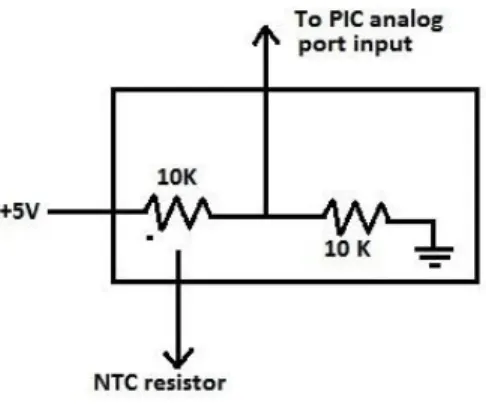
Figure 1: Temperature Sensor 2.2. Drip Sensor
For checking the drip status, two metallicprobes are taken and one of the probes isconnected to the ground. The other probeis connected to a 10K resistor. The otherterminal of the 10K resistor is connected to 5V. A tapping is made at the junction between the probe and the resistor. When there is drip fluid present in the tube, thefluid will conduct. The 5V applied at the resistor is passed through the probes and get grounded. Hence the voltage availablefor the PIC will be low (Detected as 0 by PIC) but when the drip fluid is not present in the tube, the probes will not conduct. Because of this a 5V is applied to the resistor which will be available for the PIC (Detected as 1). If a 0 is detected, it indicates that the Drip status is normal. If a 1 is detected by the PIC, it indicates drip status as abnormal. For raising an alarm, 1 is sent through the PIC’s port (RB7). This port is connected to an LED. When a 1 is received by the LED (that is 5V) the LED will light up. Similarly through another port of PIC (RB6) a 1 is sent to start the alarm. When the drip status or temperature becomes normal, we send a 0 through the PIC’s ports which will put off the LED and Alarm. Figure 2 shows the drip sensor.
Figure 2: Drip Sensor 2.3.PC and PIC Interface
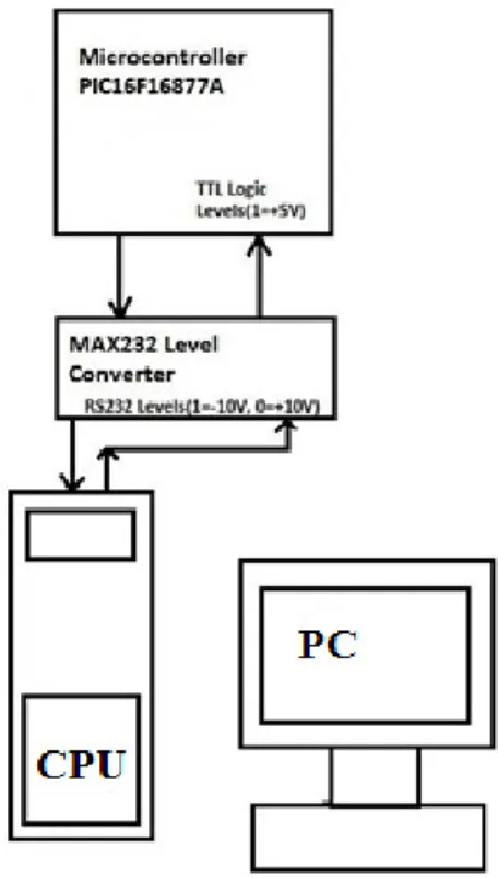
The RC6 line of PIC is connected to pin 10 of MAX232 and pin 7 of MAX232 is connected to pin2 of DB-9 connector of PC.RC7 line of PIC is connected to PIN 9 of MAX232 and pin 8 of MAX232 is connected to pin 3 of DB-9 connector of PC. The PC to PIC interface is shown in Figure 3.
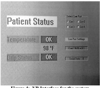
is a beginner programming language for authoring Windows – based software. It provides the GUI interface fordisplaying the sensed parameters. The VBinterface of the proposed system is givenin figure 4.
Figure 4: VB Interface for the system
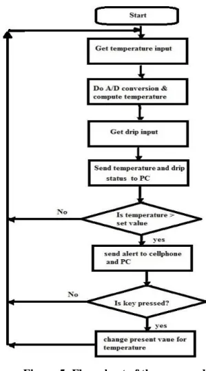
At first the temperature is sensed and taken as input through NTC thermistor. Then the temperature is computed and converted from analog to digital. Inparallel to it drip input is taken by usingmetallic probes. Both temperature anddrip status are sent to PC. If thetemperature is not greater than the setvalue (98 F) then the System restarts thesensing. If the temperature is greater thanthe set value, then an alert to cell phoneand PC is sent. If any key is not pressedin the cellphone in response to the alarmthen the sensing process restarts and thealarm keep on ringing until the doctorresponds. If any key is pressed inresponse to the alarm then the presetvalue for temperature changes to thesensed value and the alarm is automatically switched off. Then the system restarts to take the temperatureand drip input. Figure 5 shows the flowchart of the developed system.
Figure 5: Flow chart of the proposed System
4. Implementation
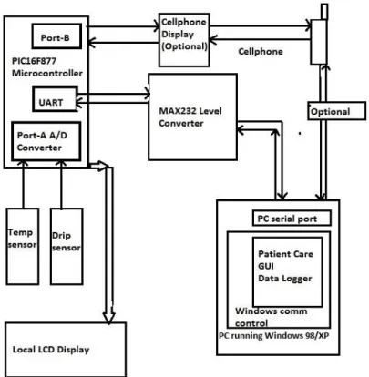
This project is implemented with microchip PIC16F877A micro controller,and sensors were used to sense the temperature and drip status. Thesesensors are hooked to the in-built Analogto digital converter of the microcontroller. The PIC16F877A micro controller also has in-built UART which can interface to a PCs serial port. Level conversion of the signals is done before connecting the UART signals of the controller to the PC. MAX232 level converter is used for level conversion. Visual basic program is used to provide the GUI program for displaying the temperature values and drip status. Visual basic contains a control called windows comm control used for communication of peripheral equipment to PC. Hence when the micro controller runs continuously, it sends the temperature and drip data to PC, and the application program continuously receive the signals and display it on the PCs display. Any discontinuity of signals from the micro controller to the serial port of the PC is also taken care of by the Windows comm control. A mobile phone is hooked to microcontroller/PC and Fbus command set is used for issuing the Send SMS command from the micro controller/PC. If any critical situation arises the micro controller issues the appropriate F-bus commands to the concerned doctor’s mobile number. The overview block diagram is given in the figure 6.
Figure6: Block diagram of the Proposed system
5. Results and Discussion
This project can also be used to monitor temperature in industrial scale were the temperature in the upper limit may notexceed about 110 C.
Utilization of the cell phone to message and the alert the user was anotheradvantage. Hence this interface could aswell be used to remotely monitor and getsalerts in case the process value exceedsthe limit. The only limits observed in thisproject are that we must ensure that cellphone is functional during the operationof this module. That is appropriatebackup power supply or charging of the cell phone batteries is needed. For this,we can always leave the charger usuallyprovided with the cell phone, connectedto the handset. In the Visual Basic SDK, we have to configure the project properties to include the MS Comm Control in this project. The properties of Comm Control (communication control) is set to have 9600 baud, no parity , 8 data bits and 1 stop bit is provided. There after we can call the Comm Control port open, Comm Control input, Comm Control Output and Comm Control port close functions. Fig 7 shows the prototype of the developed system.
6. Conclusion
This paper presents the embedded intensive care unit using PICmicrocontroller. The project is monitoring the patient’s body temperature and thestatus of drip administered and makes data logging (on PC) andreporting/alerting(using cellphone).Theavailability of in-built A/D converter inPIC16F877A has been very useful in theeasy implementation of the digitaltemperature measurement. The chip used in this project (PIC16F877A) contains 8 analog channels, of which we have used only one for temperature measurement. Inthe actual scenario in a hospital , there aremany other vital parameters to bemonitored in a patient like heartbeat,pulse rate, breathing and ventilator activity etc. this project can further be enhanced or improved by adding facilities to monitor the above mentioned parameters too. In that case the additional analog input channels will be of great use.
REFERENCES
[1] Cyber-Physical Medical and Medication Systems by Albert M. K.Cheng, 2008.
[2] Wireless Transfusion Supervision and Analysis Using Embedded System Nivedita Daimiwal, Dipali Ramdasi, Revathi Shriram, AsmitaWakankar, 2010.
[3] A low cost model for patient monitoring in Intensive care unit using a micro web-server by JoãoBosco da MotaAlver Juarez Bento da Silva ,SuenoniPaladini.
[4] Steve Heath, ‘Embedded system and design’ butterworth-heinemann publications, New Delhi, first edition, 1997.
[5] Microchip company, ‘EmbeddedSolutions’, microchip publications, firstedition, 1999. [6] TammyNoergaArdewnes, ‘EmbeddedSystems Architecture’, first edition 1999. [7] Paul Sherriff, ‘visual basic 6’, prenticehall publication, New Delhi, first edition1999. [8] Arnold Berger,’ Embedded System Design’, first edition 1997.
[9] http://www.microchip.com[pic microcontroller] [10] http://www.gnokii.org [mobile interface]
Her areas of interests are Embedded Systems and programming. She has presented a paper In ICAET-2011 held at E.G.S Pillay Engineering college at Nagapattinam.