RepliWeb
Topology Manager
User Guide
Software Version 2.1.1
For Windows, Linux and UNIX operating systems
October 21, 2009
RepliWeb, Inc., 6441 Lyons Road, Coconut Creek, FL 33073 Tel: (954) 946-2274, Fax: (954) 337-6424
ii
Copyright © 2009 RepliWeb® Inc., All Rights Reserved
The information in this manual has been compiled with care, but RepliWeb, Inc. makes no warranties as to its accuracy or completeness. The software described herein may be changed or enhanced from time to time. This information does not constitute a
commitment or representation by RepliWeb and is subject to change without notice. The software described in this document is furnished under license and may be used and/or copied only in accordance with the terms of this license and the End User License Agreement.
No part of this manual may be reproduced or transmitted, in any form, by any means (electronic, photocopying, recording or otherwise) without the express written consent of RepliWeb, Inc.
Windows, Windows NT and Windows XP are trademarks of Microsoft Corporation in the US and/or other countries. UNIX is a registered trademark of Bell Laboratories licensed to X/OPEN.
Any other product or company names referred to in this document may be the trademarks of their respective owners.
Please direct correspondence or inquiries to:
RepliWeb, Inc. 6441 Lyons Road
Coconut Creek, Florida 33073 USA
Telephone: (954) 946-2274
Fax: (954) 337-6424
Sales & General Information: [email protected]
Documentation: [email protected]
Technical Support: http://support.repliweb.com
iii
Table of Contents
1. INTRODUCTION ... 1
THE REPLIWEB FAMILY OF PRODUCTS ... 1
ABOUT THE USER GUIDE ... 2
2. OVERVIEW ... 3
GENERAL CONCEPTS... 3
FUNCTIONAL DESCRIPTION... 4
ARCHITECTURE ... 4
3. REPLIWEB TOPOLOGY MANAGER CONSOLE ... 6
CONNECT DIALOG ... 6
HOST DEFAULTS ... 9
MANAGING HOSTS ... 10
Menus & Toolbars ... 11
Information Tab ... 13
Hosts Tab ... 14
Scheduler Tab ... 16
Recovery Options Window ... 19
Email Configuration Tab... 21
Users Definition Tab ... 23
Security Rules Tab ... 26
License Tab ... 31
SSL Tab ... 33
PAM Service Tab ... 36
Disk Space Tab ... 37
Tools Tab ... 39
Change Password ... 40
Run Command ... 44
Migration ... 45
Manage Internal Processes Tab ... 47
Internal Processes - Eraser ... 47
Internal Processes - Failover ... 49
Internal Processes – Backup & Restore ... 53
Backup Settings ... 55
Backup Settings – General Tab ... 55
Backup Settings – Error Handling Tab ... 57
Backup Settings – On Exit Tab ... 58
Restore Wizard... 59
Restore Wizard - Select Location ... 59
Restore Wizard - What to Restore ... 60
Restore Wizard - Jobs ... 61
Restore Wizard - Error Handling ... 62
Restore Wizard - Summary ... 63
Restore Wizard - Progress ... 64
PROPAGATE SETTINGS ... 65
APPENDICES ... 69
APPENDIX A – QUICK GUIDE ... 70
1
1. Introduction
RepliWeb, Inc. is a full service technology company that develops innovative software for data replication and deployment. Its primary clients are S/M/L Enterprises,
Technology Developers, Integrators and Global Service Providers.
The RepliWeb Family of Products
RepliWeb products helping your IT organization deliver strategic file workflow, content automation and information delivery solutions faster—and more reliably. RepliWeb‘s software solutions automate, guarantee, and accelerate the delivery of files throughout local and distributed enterprise-computing environments. Installed in some of the most demanding enterprise IT and datacenter environments, RepliWeb solutions accelerate information availability, deliver improved performance, and reduce costs associated with content-based file workflows.
R-1 Deployment Platform (R-1) – Automated deployment of web content, IIS6
Metabase, .NET framework and COM+ components to data centers and across local or distributed computing environments.
RepliWeb Directory Synchronization (RDS) – A peer-to-peer file replication and file
synchronization solution for heterogeneous computing environment (Windows, Linux, UNIX).
RepliWeb Operational Synchronization for SharePoint (ROSS) – A deployment
solution for SharePoint©-enabled organizations publishing across tiered topologies and multiple farms.
RepliWeb Managed File Transfer (RMFT) – A managed file transfer platform that helps
organizations automate file workflows and accelerate the way they transfer, share, and exchange files between internal users, customers, and business partners.
A complete list of products and supported platforms can be found at RepliWeb‘s web site: http://www.repliweb.com.
2
About the User Guide
AudienceThis guide was written with the following in mind:
The user is familiar with the various Microsoft Windows operating systems (Windows NT / Server 2000 / XP / Vista (32/64-bit Editions) Server 2003/ Server 2008 (32/64-bit Editions)) as well as the UNIX operating system (should the replication job employ it) and their basic administration.
The user has the necessary privileges for the computer(s) on which the software is to be installed. These will be described more fully throughout the User Guide. The user is familiar with Windows-style graphical user interfaces (GUI) and / or
command line interfaces (CLI).
User Guide Organization
RepliWeb Topology Manager has been designed to operate between Windows environments, UNIX environments, and heterogeneous (mixed) environments, communicating with other RepliWeb systems (RDS/R-1/ROSS).
The User Guide explains the various RepliWeb Topology Manager capabilities through a graphical user interface screens (RepliWeb Topology Manager GUI).
NOTE: RepliWeb Topology Manager does NOT create any default user or password. All user names and passwords used in this guide are samples only.
3
2. Overview
This chapter provides a high-level description of RTM‘s functionality, architecture and main features. It also talks about the basic terminology that is used throughout this document.
General Concepts
MissionRepliWeb Topology Manager is a tool designed to provide RepliWeb customers using RDS/R-1/ROSS with centralized management capabilities for their RepliWeb hosts. RepliWeb Topology Manager can connect to any RDS, R-1, and/or ROSS machine, regardless of the components installed on it (this can be an RDS Controller, an R-1 or ROSS Center, an RDS Satellite, an R-1 or ROSS Edge, and any combination of them).
NOTE:For brevity, the terms Center and Edge are used throughout this guide to denote
(R-1/ROSS) Center / (RDS)Controller and (R-1/ROSS) Edge / (RDS) Satellite, respectively. RepliWeb Topology Manager is an extension to the RDS, R-1, and ROSS Consoles, providing management features not included in the standard Console GUI.
NOTE: The following chapters describe the RepliWeb Topology Manager interaction among RDS, R-1, and ROSS components like Center and Edge.
RepliWeb Topology Manager Features
Verify version information Handle Hosts list
Manage licenses
Configure Scheduling properties Define and test e-mail configuration Execute remote commands
Manage Virtual Users
Configure disk space thresholds Specify security rules
Open a Console GUI for each host Define SSL communication
4
Functional Description
RepliWeb Topology Manager provides RDS/R-1/ROSS administrators with management capabilities for their RepliWeb hosts. The list of RepliWeb nodes is maintained by the user, adding groups and hosts, reflecting the actual topology, on one of the Centers. Once connected with the Enterprise Manager Console, the user can connect to any of the Hosts on the list, and displayed with various management options. Information about the installed components information from that node is displayed, the user may manage the Hosts list on that node, setup Scheduler properties, manage its licenses, configure E-mail properties, execute batch files on the remote node, handle virtual users and security rules.
Any RDS, R-1, or ROSS machine may be connected, regardless of the components installed on it (Center and / or Edge).
Once connected to a host, if this host is the Center, the Console GUI for that machine can be opened.
Architecture
RepliWeb‘s flexible architecture allows the user to connect to any machine regardless of the network configuration or operating system being used. The RepliWeb Topology Manager console can connect to any Windows-to-UNIX machine that has RDS, R-1, and/or ROSS installed.
5
Terminology
The RepliWeb Topology Manager Console may connect to any Center to centrally maintain the list of all RepliWeb hosts in the organization.
The RepliWeb Topology Manager Organizer is any Center, on which the
organization‘s Hosts listis maintained. Users may maintain different lists on different machines to reflect administrative roles and security.
Host
Any machine that has a Center or an Edge installed may be added to the list of Hosts maintained in RepliWeb Topology Manager. Connecting to a host enables managing and setting RDS/R-1/ROSS properties to multiple hosts.
Connecting to a Host which is the Center that is using an administrator‘s credentials (members of Administrator groups on Windows, and root on UNIX) also allows the user to open the standard GUI to that Host. This enables administrators to centrally monitor multiple Centers simultaneously.
Group
Hosts may be grouped in a multi-level tree structure to reflect the replication and distribution topology of the organization. There is no limit to the number of Hosts and Groups or the number of tree levels.
6
3. RepliWeb Topology Manager
Console
The RepliWeb Topology Manager Console enables the user to connect to any RDS/ R-1/ROSS machine. This can be either a Center or an Edge.
The RepliWeb Topology Manager Console provides a centralized management point of all RepliWeb hosts in the organization, organized in an easily managed tree structure, reflecting the organization‘s replication and deployment topology.
NOTE: The RepliWeb Topology Manager Console installation requires the appropriate Console (RDS/R-1/ROSS) to be installed first.
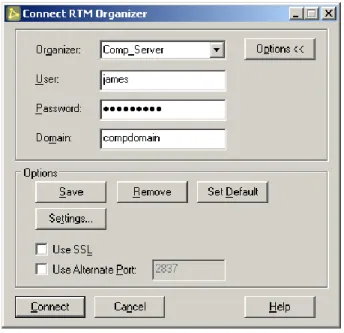
Connect Dialog
The first step is to connect to the RepliWeb Topology Manager Organizer. Then, once connected to where the Hosts list is maintained, add a Host to the list.
Figure 2: Connect Organizer Dialog
NOTE: Only members of the Administrative Privilegesgroup can connect to the
RepliWeb Topology Manager Organizer. Connected to a UNIX Center, use root or root-like users (UID and GID 0); connected to a Windows Center, use a member of the Administrator group on the Center.
7
Once connected, using the hosts list, double click the host, or click the Connect button, theConnect Dialog is opened, this time to enter connection credentials to the selected host.
Figure 3: Connect Host Dialog
Organizer / Host– Enter the host name or IP address of the host being
accessed. RepliWeb Topology Manager saves, according to user settings, the connection credentials of each of the Hosts the Console is connecting to, so hosts the user already connected to it can be selected from the list.
NOTE: When connecting to the RepliWeb Topology Manager Organizer, the machine must be either a Center or an Edge while connection to a Host, the machine can be a Center or an Edge, or any combination of them.
User– Enter the user name to connect to the remote host.
Password – Enter the password for the account specified in the User field. Domain – If user is part of a domain, enter the domain here, if it is not, leave this
field blank.
Connection credentials can include the password with/without confirmation if the user selects to do that; the password is saved in an encrypted format.
When all the necessary fields are filled in, click Connect.
Connect– Connects to the host specified. Connection credentials are saved
according to the settings specified by the user. The user can elect to always add the Center‘s connection credentials to the list upon successful connection to the Center.
This window allows saving the list of RepliWeb Topology Manager Organizers and Hosts the user connects to from the Console.
8
Figure 4: Connection Screen Options
NOTE: The Organizers list is saved locally on the machine RepliWeb Topology Manager Console is running from and is user specific. The Hosts list is saved on the RepliWeb Topology Manager Organizer and is available to anyone who connects to this Organizer using RepliWeb Topology Manager.
Options – Clicking the Options button enhances the screen to allow more connection options and saving connections setting options.
Save– Save connection credentials according to the settings specified by the
user regardless of the validity of the values entered.
Remove– Remove the Center‘s connection credentials from the list.
Set Default – Use the current connection credentials as the default for RepliWeb
Topology Manager to use the next time the console is opened.
Settings – Specify whether the connection credentials will be saved with/without
the password, and whether saving confirmation is required. This window also allows specifying that the connection credentials will be automatically saved upon successful connection to the Center.
NOTE: When saving passwords, the password is always encrypted! Use SSL– Specify whether to connect to that Host using SSL protocol.
Use Alternate Port– Check this option to change the port being used for
Console – Organizer and Console – Host communication, and specify the new port number to use.
9
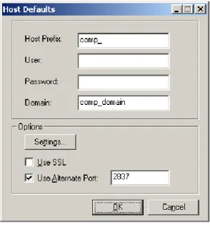
Host Defaults
The RepliWeb Topology Manager Organizer allows specifying defaults for new hosts added to the hosts tree. This makes it easier when adding many hosts and using corporate defaults.
Figure 5: Connect Organizer Dialog
Host Prefix– If most of your hosts begin with the same prefix, enter it here. It will
be used whenever you add a new host to the tree.
User– Enter the default user name to be used in the connection screen of new
hosts.
Password– Enter the default password to be used in the connection screen of
new hosts.
Domain – If user is part of a domain, enter the default domain here. It will be used in the connection screen of new hosts.
Use SSL– Specify whether to connect to new hosts using SSL protocol.
Use Alternate Port– Check this option to change the default port being used for Console-Organizer and Console-Host communication, and specify the new port number to use.
10
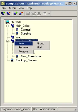
Managing Hosts
To maintain the list of RepliWeb hosts, hosts and groups are added, in a tree structure. The Tree structure may be organized in any way the user prefers. It can reflect the organization‘s replication topology; it may match a geographical topology, or just be a flat list of hosts.
Any RDS/R-1/ROSS machine can be added and connected to the Hosts list, regardless of the components installed on it (even if it is just an Edge).
Figure 6: Managing the Hosts Tree
The Host name is the DNS name or IP address of the machine. The Group name has no function so it may be any text the user selects.
Connected hosts appear in bold. Once connected to a host, if this host is the Center, the Console GUI for that machine can be opened.
Operations that can be performed on the main screen and the tree by using: the toolbar, application menu and floating menu (using the right-mouse button). See detailed
description below.
See Appendix A – Quick Guide for step-by-step instructions on how to add hosts and groups.
11
Menus & Toolbars
Figure 7: The Menu & Toolbar
The application menus provide access to all RDS/R-1/ROSS functions.
File – Create a new Host or group of hosts and connect to a different RepliWeb
Topology Manager Organizer.
Action – Operate on the selected host or group: connect/disconnect, rename,
remove, manage and open the Console.
View – Select to view or hide the status and tool bars.
Help – Initializes the RepliWeb Topology Manager help. From the Help menu the
user can also access RepliWeb‘s online knowledge base and support form.
Toolbar Buttons
The toolbar is analogous to the toolbar functions in most standard Windows applications. As such, the toolbars may be undocked and placed at any place in the main Job List window.
Tool tips appear when the pointer is held over each button.
Listed below are the buttons available on the RepliWeb Topology Manager Console.
Button Function Description
New Group Add a new group to the Hosts tree. The group is added
beneath the currently selected group.
Remove Group Click this button to remove the selected group
New Host
Add a new Host to the Hosts tree. The Host is added to the currently selected group. Enter the DNS name or IP address of the host.
Remove Host Click this button to remove the selected host.
12
Button Function Description
Disconnect Click this button to disconnect from the selected host.
Manage Click this button to manage the selected host.
Console
Click this button to activate the selected Console (RDS/R-1/ROSS). The appropriate Console will open, depending on the RepliWeb application installed on the host.
NOTE: This button is available only if the user has connected to the host.
13
Information Tab
The Information tab displays the build date and version of the various RepliWeb components installed on the host. In addition, it displays the operating system of the host.
To access the Information tab:
Right click the required host, select Manage, and then Information from the left pane.
14
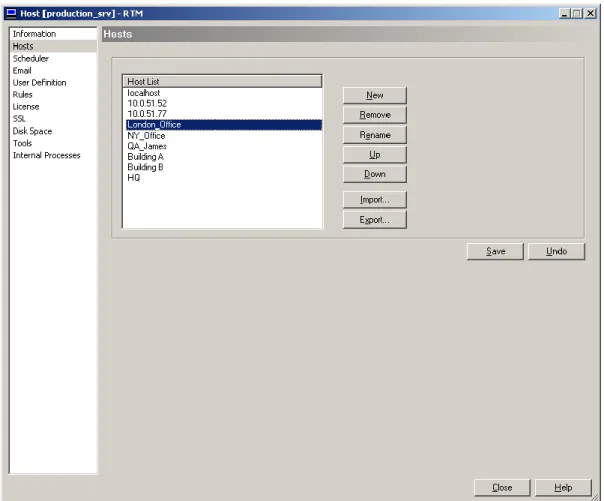
Hosts Tab
The Hosts tab allows updating the Hosts list on the managed host.
This tab is available only for hosts that have a Center component installed.
To access the Hosts tab:
Right click the required host, select Manage, and then Hosts from the left pane.
Figure 9: Managing Hosts
The RepliWeb Hosts list resides on the Center, listing the hosts the user can replicate between.
This tab allows changing the order of the hosts in the list, and also exporting and importing the list of hosts. This enables easy assignment of the same hosts list in the entire organization.
New– Add a Host to the hosts list
Remove–Remove a host from the hosts list Rename–Rename a host in the hosts list
15
Down–Move the selected host one level down the list
Import–Import a list of hosts from a file on the RepliWeb Topology Manager Organizer machine.
Export–Export the list of hosts to a file on the RepliWeb Topology Manager Organizer machine.
Save–Save the list of hosts to the Hosts file on the remote Host.
Undo–Undo changes done to the list. The list of hosts is re-loaded from the remote host.
NOTE: None of the changes will take effect until the Save button is clicked. Only new jobs will be affected by these changes.
16
Scheduler Tab
The Scheduler tab enables the user to set the Scheduler properties. This tab is available only for hosts that have a Center component installed.
To access the Scheduler tab:
Right click the required host, select Manage, and then Scheduler from the left pane.
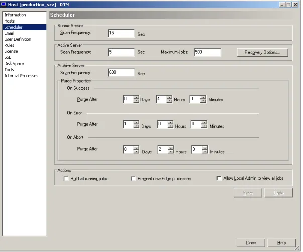
Figure 10: Scheduler Properties
Submit Server– Specify the Scan Frequencyof the Submit server. This value specifies how frequently the server will check if scheduled jobs need to initiate new jobs.
Active Server– The Active server is responsible for status changes of all
running (active) jobs.
o Scan Frequency – Specifies the frequency the Active server will scan the
running jobs and determine actions that need to be taken (i.e. move to archive, execute exit command, activate recovery, etc.).
17
o Max Jobs– Specify the maximum number or simultaneously running
jobs. If there‘s a job that is scheduled to run every minute that distributes data to multiple Edges, and the server is down, when the server is
running again, all pending jobs will try to run at once. Limiting the number of jobs, will queue the rest of the jobs until one of the currently running jobs had completed.
o Recovery Options– Replication & Distribution operations can recover
after unexpected errors such as communication line or network faults, user interruption, or even a system crash. In anticipation of these errors, the Center maintains an ongoing record of its progress through each distribution job.
Click this button to open the Recovery Options window for setting recovery options.
Archive Server– The Archive server is responsible for handling completed jobs.
Configure here the Purge Policy depending on the completion status of a job.
NOTE: When a job has reached its purge age, it will be deleted. A purged job is no longer viewable through either the Console CLI or the Console GUI.
Each job generates report files that can be used for monitoring purposes. Since these reports can consume vast amounts of disk space, they are automatically purged after a predetermined amount of time. This means that they will
disappear from the Console GUI, and not be visible by a Console CLI show
command.
The Scheduler‘s Archive Server can be configured to have different purge policies for different job completion statuses. For example, a job that exited with error may want to be kept much longer than a job that completed successfully. The Abort / Error / Success Purge Policy fields are in minutes, and will govern how long a job record will be kept after completion.
By default, job reports will be kept like this:
Successful Jobs - 4 hours (240 minutes) Aborted jobs - 2 hours (120 minutes) Failed jobs - 24 hours (1440 minutes)
o Scan Frequency– This value specifies how frequently the server will
check if jobs are to be purged.
As RepliWeb product architecture is designed to be robust and resilient to failures, the purge command is performed in an asynchronous way. When the purge command is issued, the job is "only" marked to be purged, and the actual deletion is performed on a scheduled basis. This means that the user can issue a purge command, reboot the Center server before the jobs are actually deleted and when the server is started the purge
18
operation will still take place.
o OnSuccess / Error / Abort– A different policy can be specified for each
completion status.
Purge After – Specify the duration (Days/Hours/Minutes) in which
to keep the Job‘s reports.
Actions (Administrative Hold)–These two administrative tasks are to be used on the Center or Edge prior to RDS/R-1/ROSS upgrades, or before other general maintenance activities that require the administrator to stop all processes on the servers.
o Hold all running jobs – Put on hold all running and scheduled jobs. This
is an administrative task that will put on hold all Replication and Distribution jobs regardless of their originating user.
o Prevent new Edge processes – Check this option to prevent new
processes on the Edge (replication, cleanup, snapshot, etc.) from being initiated. Note that running RepliWeb processes will not be stopped and will continue until completion. The Edge will not accept download or upload requests, Scheduled or Continuous Update jobs that involve this Edge will fail at initiating new job instances.
o Allow Local Admin to view all jobs – Check this option to allow all
members of Local Admin group on the Center to view all jobs via the Console. When this option is un-checked, only the user who submitted the jobs (and users that were authorized to view the job) will be able to view and monitor the job.
NOTE: None of the changes will take effect until the Save button is clicked. Only new jobs will be affected by these changes.
Save –Save changes to the configuration files on the remote host.
Undo All –Undo changes done to the configuration files. Values are re-loaded from the remote host.
19
Recovery Options Window
Replication and Distribution operations can recover after unexpected errors such as communication line or network faults, user interruption, or even a system crash. In anticipation of these errors, the Center maintains an ongoing record of its progress through each distribution job.
In the event of failure, the product used obtains all necessary information regarding the failed operation from the record generated, including the original property configurations and the exact point of failure.
This window can be used to specify recovery options for Replication, Distribution and Edge jobs, including recovery attempts interval and recovery notifications.
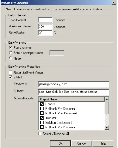
Figure 11: Recovery Options
Retry Interval– Specify the interval calculation between recovery attempts:
o Base Interval – The time interval before the next attempt is made.
o Maximum Interval – The maximum period of time to which the interval
between recovery attempts may accumulate based on the Base Interval
and the Retry Factor.
o Retry Factor – An incremental increasing factor used to geometrically
20
Example:
A job has a Max Retries of 6, a Base Interval of 10 minutes (600 seconds), a Retry Factor of 50%, and a Max Interval of 60 minutes (3600 seconds). The job was submitted at 5:05 AM:
Recovery attempt 1 of 6 will occur at 5:15 (10 minutes after the failure) Recovery attempt 2 of 6 will occur at 5:30 (15 minutes after the last failure) Recovery attempt 3 of 6 will occur at 5:53 (23 minutes after the last failure) Recovery attempt 4 of 6 will occur at 6:27 (34 minutes after the last failure) Recovery attempt 5 of 6 will occur at 7:18 (51 minutes after the last failure) Recovery attempt 6 of 6 will occur at 8:34 (76 minutes after the last failure) Recovery attempt 6 of 6 will not occur since the interval has increased to 76 minutes surpassing the Max Interval of 60 minutes.
Early Warning – Administrators can receive early notification when jobs are in
recovery, enabling them to fix the situation and allow the job to continue
uninterrupted, before the job exhausts its recovery attempts. Notification can be sent by email and / or by reporting to Event Viewer.
o Every Attempt –Notify on every recovery attempt.
o Before Attempt Number – Notify after the specified number of recovery
attempts.
o Never – Do not notify
Early Warning Settings
o Report to Event Viewer – For each completion type, report the Job‘s exit
message to the Windows Event Viewer or the UNIX syslog.
o Email – An email is sent as a notification that the Job is in recovery.
o Recipients – Enter the email address of the email recipient(s). More than one email address may be entered. Multiple email addresses should be separated by commas.
o Subject – Edit the subject of the email to be sent. The subject line may
include information about the job:
$job_type
$job_id
$job_name
$status
A subject line is specified in the job properties as follows:
$job_type[$job_id]: $job_name, is in recovery.
This particular subject line will appear in an email as follows:
Distribution [2362]: Weekly Updates, is in recovery.
o Attach Reports– Select the replication reports to be attached to the
email. The list of reports depends on the Job type – Replication, Distribution, Rollback.
21
Email Configuration Tab
As RDS/R-1/ROSS can be set up to send email upon job completion, e-mail configuration parameters should be set on the Center.
This tab is available only for hosts that have the Center component installed.
To access the Email tab:
Right click the required host, select Manage, and then Email from the left pane.
Figure 12: Email Configuration
Configuration
o SMTP Host Name– Enter the IP Address or name of the Email server
o SMTP sender– Enter the Email address that appears in the From field of the mail. It does not necessarily have to be an actual account.
Format is [email protected].
o Use sender password authentication–Check this option if your Email server is secured.
User–Email server authenticating user name
Password–Password of the Email server authenticating user name
22
Email Test– Enter the Email address of a recipient to test the email
configuration settings, and click the Test button. Upon successful email-sending, the user will be prompted to save the configuration settings, if those were not already saved.
Save– Save email configuration properties on the remote host.
23
Users Definition Tab
The User Definition tab enables you to define virtual and real users to convert them to real users.
To use a virtual user between the Centerand an Edge, you should connect to the Edge. If you want to use a virtual user between Console and Center, connect to the Center. Virtual users are defined on the machine accepting the connection. This way, the machine initiating the connection ―knows‖ only virtual information and only virtual
information is sent on the network. Real information never leaves the machine accepting the connection.
NOTE: In UNIX, you can only define virtual users. No need to define real users to be used in the Rules Tab. In Windows, in order to map a virtual user to a real user, the real user must be defined in the User Definition tab as well.
To access the User Definition tab:
Right click the required host, select Manage, and then UserDefinition from the left pane.
24
For additional explanation on Security Rules and Virtual Users, refer to Appendix B –
Proxy User Security Mechanism.
NOTE: Do not define real users if there are no virtual users mapped to them. 1. Click the leftmost button to add a new user.
Figure 14: Adding Virtual Users
2. Add the virtual user and virtual password. 3. Select the Virtual option and click OK.
NOTE: If you define that virtual user with a domain (a virtual one), you should also specify that domain name in the Connection screen.
4. Add the real user that the virtual user is translated to by selecting the System
option and entering a real Domain:
Figure 15: Adding Real Users
25
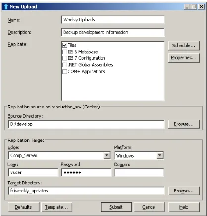
Updating the Submit Command
Assuming that you have defined virtual users on an Edge, you can go back to your CLI
submit command on the Console, and change the user/password combination for the remote connection:
Instead of:
> … submit … -user=real-user –password=*** –domain=compdomain
you can now specify:
> … submit … -user=vuser –password=vpass
Using the Console GUI, your job definition will look like this:
26
Security Rules Tab
The Security Rules tab enables you to define rules that apply to system and virtual users.
Security rules are defined on the machine accepting the connection, as this is where access to system and virtual users is granted or denied. Here you define the connection between the virtual user and the real user.
To use security rules between the Center and an Edge, you should connect to the
Edge. If you want to use security rules between Console and Center, connect to the
Center.
For additional explanation on Security Rules and Virtual Users, refer to Appendix B –
Proxy User Security Mechanism.
To access the Rules tab:
Right click the required host, select Manage, and then Rules from the left pane.
27
To define a rule:
1. Click the leftmost button ―New Rule‖ to add a new rule –
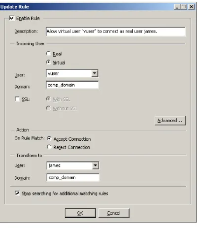
Figure 18: Adding a Rule
Enable Rule – Specify whether this rule is enabled or not. If this option is not
selected the rule is not taken into account while evaluating a user.
o Description– Fill in a description of that rule. This field has no effect on
the rule‘s functionality.
o Incoming User – specify the user name performing the connection. This
user name will be translated to a real user on the target machine. Specify whether the incoming user is Virtual or not.
If the incoming user is a virtual user, you can define a virtual domain as well. The domain is then used in the actual connection command.
NOTE: In UNIX, you can only define virtual users. No need to define real users to be used in the Rules Tab. In Windows, in order to map a virtual user to a real user, the real user must be defined in the User Definition tab as well.
- In a Console Center / Host connection, the incoming user is the one used in the Console Connection screen.
28
- In a Center Edge connection, the incoming user is the one used in the job definition.
SSL – Specify if to consider SSL during the connection:
With SSL – The connection must be with SSL
Without SSL – The connection must be without SSL. o Action– specify whether the rule is ―positive‖ – approve the user to
connect (Accept Connection), or ―negative‖ – deny access to that user
(Reject Connection).
o Transform To– specify the real target user the Incoming User is translated to.
If applicable, specify Domain.
NOTE: If the virtual user was defined with a domain (a virtual one), you should also specify that domain name here.
This is a basic rule. Since you defined only one user, simply click OK
to specify that the user ―vuser‖, will be examined as a virtual user and translated to the real user ―james‖ from the domain ―comp_domain‖. Stop searching for additional matching rules – Do not check that user using
other rules. If the incoming user matches that rule, accept or deny according to that rule.
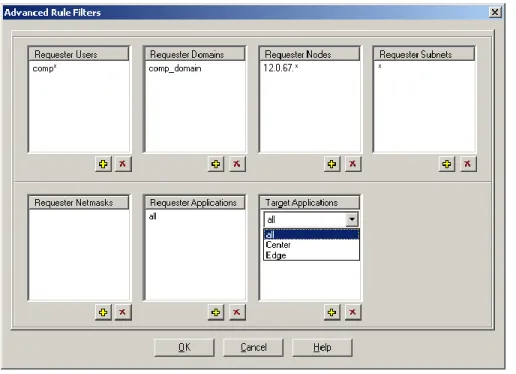
Advanced – Rules may be further enhanced to tighten security and limit
accessibility to RDS/R-1/ROSS machines. These features describe the operating system environment from which the connection request is coming from.
29
Requester Users – Wildcard and multiple values are supported.
- In a Console Center connection, this is the ACTUAL ACCOUNT from which the RDS/R-1/ROSS command came from, i.e. Windows or UNIX account, not the Console login.
- In a Center Edge connection, this is the user used in the Console login to the Center.
Requester Domains – Wildcard and multiple values are supported.
- In a Console Center connection, this is the ACTUAL Windows domain from which the RDS/R-1/ROSS command came from.
- In a Center Edge connection, this is the domain of the user used in the Console login to the Center.
Requester Nodes – The machine name from which the request comes from.
Wildcard and multiple values are supported.
- In a Console Center connection, this is the network name of the Console machine.
- In a Center Edge connection, this is the network name of the Center. Requester Subnets – The subnet from which the request comes from. Wildcard
and multiple values are supported. For example - 17.0.84.*.
- In a Console Center connection, this is the subnet of the Console machine.
- In a Center Edge connection, this is the subnet of the Center. Requester Netmasks – The netmask from which the request comes from.
Wildcard and multiple values are supported. 255.255.255.0 - for example.
- In a Console Center connection, this is the netmask of the Console machine.
- In a Center Edge connection, this is the netmask of the Center. Requester Applications – The application name from which the request comes
from. Multiple values are supported, and ALL can be selected meaning the request can come from any of the listed applications. This field can have the following options: o Console o Command Line o API o Replication Job o Multicast Distribution o Manage
Target Applications – The target application receiving the connection request.
This field can have the following options: o Center
30
o Edge
In the screen-shot above, only users that their name begins with ―comp‖, from
domain ―comp_domain‖, and that are connecting from machines whose IP
address begins with 12.0.76 are allowed to connect. Other users will not pass that rule and their connection request will be denied.
2. Click the Save button.
3. Defining a few rules, you can determine the order in which the rules are applied when a user tried to connect to the machine. To update the location of a rule, right-click the rule, and in the floating menu select the Move option. A window will open, enabling to move the rule up and down between the existing rules.
31
License Tab
This window enables managing product Licenses on the remote Host.
NOTE: Handle RepliWeb licenses with care. Follow the instructions you received from RepliWeb support.
To access the License tab:
Right click the required host, select Manage, and then License from the left pane.
Figure 20: Licensing
License Type – Select the license type (RDS/R-1/ROSS).
Remove– Remove the license from the remote machine.
NOTE: RDS, R-1, and ROSS are licensed RepliWeb applications. Removing any RepliWeb application‘s license without direct instructions from RepliWeb support will disable it.
32
Install– Save the viewed license on the remote host. Use the license received
from Repliweb. Either copy the license from the email and paste it in the license window, or import a saved license from the RepliWeb Topology Manager Organizer machine.
Undo–Discard changes done in the license window, reload license from the remote Host.
Export–Export the license in the window to a file on the RepliWeb Topology Manager Organizer.
NOTE: RepliWeb Licenses are digitally signed. Do not make any changes to the text.
33
SSL Tab
RepliWeb products use OpenSSL to enable Encryption and Authentication for:
Console Center communication effective for Console Center,
RepliWeb Topology Manager Console RepliWeb Topology Manager
Organizer and RepliWeb Topology Manager Console RepliWeb Topology
Manager Host.
Center Edge communication effective for WAN transfer replication and R-1/ROSS distribution jobs.
SSL sessions can be configured using the RepliWeb Topology Manager GUI and Managed in the Console GUI user interfaces.
NOTE: For maximal data-security, although the key-phrase is encrypted at all times, it is recommended to set SSL configuration using a local Console on each of the machines, and not over the network.
To access the SSL tab:
Right click the required host, select Manage, and then SSL from the left pane.
34
NOTE: Use the default certificate and key provided with the product to configure and test SSL communication. However, for production environment, it is recommended to use certificates provided by a Certificate Authority (CA).
For a step-by-step explanation about setting SSL security, see your RepliWeb product‘s
SSL Guide.
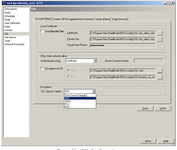
Internal Tabs– Select one of the 4 end-points to configure.
o Console (Client)– Configure the Client in a Console Center
communication.
o Center / RepliWeb Topology Manager Organizer / RepliWeb
Topology Manager Host (Server) – Configure the Server in a Console
Center communication.
o Center (Client) – Configure the Client in a Center Edgereplication process communication.
o Edge (Server) – Configure the Server in a Center Edgereplication process communication.
Local Certificate– Specify how the machine being configured introduces itself in
the Authentication stage.
o Use Alternate Files– Specify the Certificate and Key file names to be
used. If unchecked – default certificate, private key and private key phrase will be used. If checked, the following will be used:
Certificate – Specify the full path to the CA Certificate file.
Private Key – Specify the full path to the private key file.
Private Key Phrase – Specify the password to read the private
key file. The key phrase is kept encrypted and hidden.
NOTE: The private key phrase is kept encrypted for each Windows Login user separately.
Other Side Authentication– Specify how the machine being configured verifies
the other side in the Authentication stage.
o Authenticate Using–Select the authentication type that will take place:
Certificate – Authenticate the other end using a certificate.
Certificate + Name– Authenticate the other end by using a
certificate and the Common name written in certificate.
None–Do not authenticate the other end. The SSL session will use encryption but not authentication.
o Server / Client Common Name–When using authentication by name, this name will be expected in the other end‘s certificate.
o Use Approved CA–If unchecked - default certificate, private key and private key phrase will be used. If checked, the following will be used:
CA File – Specify the full path to a file containing trusted
certificate authorities information.
CA Dir– Specify the full path to a directory containing trusted
35
Encryption– Select the encryption type to use during the SSL session. Options
are:
o DES – DES (Data Encryption Standard) applies a 56-bit key to each
64-bit block of data.
o 3DES – Triple DES
o RC2 – RC2 (Rivet‘s Cipher 2) is a variable key-size block cipher.
o RC4 – RC4 is a variable key-size block cipher with a key size range of 40
to 128 bits. It is faster than DES and is exportable with a key size of 40 bits.
o Use Server Defaults – The encryption type is selected by the server
automatically.
NOTE: Encryption can be set in Client side only.
For a step-by-step explanation about setting SSL security, see your RepliWeb product‘s
36
PAM Service Tab
Using PAM authentication, RTM administrators can enable users on LDAP repositories, such as Microsoft‘s Active Directory, to log into UNIX machines using their own account credentials without having to create a unique login account for each relevant UNIX machine.
To access the PAM Service tab:
Right click the required host, select Manage, and then the PAMService tab in the left pane.
Figure 22 – PAM Authentication
To configure PAM authentication:
1. Select the Use PAM Service checkbox.
2. Enter the appropriate PAMService Name. Default is ―repliweb‖. 3. Enter the PAM LibraryPath. For example, /lib/libpam.so.0.81.5
37
Disk Space Tab
Use this tab to configure the disk space thresholds allowed and the system‘s behavior whenever a disk space problem or shortage occurs.
To access the Disk Space tab:
Right click the required host, select Manage, and then Disk Space from the left pane.
Figure 23 – Disk Space Configuration Installation Drive SpaceThreshold
o Minimum required disk space – Set the minimum disk space (in MB)
that is required on the installation drive for proper operation. o When the installation drive threshold is reached:
Prevent jobs from running – (enabled for Centers only) Hold all
jobs from running until there is sufficient disk space.
Reject job connections from other Centers – (enabled for
Edges only) Reject any future job connections from other Centers until there is sufficient disk space.
38
Report to Event Viewer – Report this issue to the Windows
Event Viewer or the UNIX syslog.
Email to – Enter the recipient(s) email address to be used when
the installation drive threshold is reached. More than one email address may be entered. Multiple email addresses should be separated by commas.
Archived Jobs Disk Space Threshold
NOTE: This section is enabled for Centers only.
o Disk space allocation threshold – Set the maximum disk space allowed
(in MB) for the archived jobs directory.
o Archived jobs folder – Displays the path to the archived jobs folder.
o When the disk space threshold is reached:
Purge jobs when exceeding the disk space threshold – Once
the disk space threshold is reached, the system will begin purging archived jobs based on the oldest purge date until the archived jobs directory limit is surpassed.
- Purge jobs that are set to “Never Purged” if there is
still insufficient disk space – When purging jobs
does not clear enough disk space, the system will begin purging jobs that were set to Never Purged until the archived jobs‘ disk space limit is reached.
o Report to Event Viewer – Report this issue to the Windows Event
Viewer or the UNIX syslog.
o Email to – Enter the recipient(s) email address to be used when the
installation drive threshold is reached. More than one email address may be entered. Multiple email addresses should be separated by commas.
39
Tools Tab
The tab enables access to various management tools.
To access the Tools tab:
Right click the required host, select Manage, and then Tools from the left pane.
Figure 24: Management Tools
Change Password – Use the Change Password utility to update scheduled jobs‘
passwords.
Run Command – Use this option to execute commands on remote hosts.
Migration – Use this option to migrate RDS jobs to R-1 jobs.
40
Change Password
Use the Change Password utility to update Jobs, Templates and configuration files whenever a password change occurs.
Examine the following scenario:
User ‗bob‘ defines a scheduled job, and gives the following credentials to connect to the Edge:
Edge=103.20.161.102 User=bob
Password=aba
The job starts to run using these credentials.
One hour later the user‘s password on the Edge expires (its his company policy) and he needs to change his password.
He changes the password on the Edge from ‗aba‘ to ‗daba‘.
From now on, new instances of this scheduled job will fail, as the supplied credentials are invalid, because they try to connect to the Edge using the old password, which is no longer valid.
All recovery tries will fail and, the account of that user may be locked because there were too much retries to login with bad credentials.
Using the Change Password utility, the user can automatically update the password for all jobs. Without this utility, the user had to resubmit all jobs that use the old password, and update them to use the new one.
Changing passwords may be done using this screen, or using command line by activating this Change Password utility located in the RDS installation path ~Program Files\RepliWeb\RDS\utilities.
41
Figure 25: Change Password Wizard – Welcome Page
Back– Go to the previous wizard page.
Next – Click the Next button after filling the required fields in the current page.
Finish– Click the Finish button to perform the change password process.
Cancel– Cancel the wizard. Change password utility is not activated.
Figure 26: Change Password Wizard – Hosts
In the Hosts page, specify the identities (names, IP addresses and/or aliases) of all the hosts on which you want to change the user‘s password. Several identities may have been specified for the same host. For example, the user may have submitted on job using the host‘s IP address and another job using the host name. In this case, both values should enter the list.
42
NOTE: If the machine specified is the localhost machine (the same machine on which you run the utility), you must specify either the name of the machine, its IP address or ―localhost‖.
In general, it is recommended to always specify also the name of the machine.
Figure 27: Change Password Wizard – Specify Credentials
In the Credentials page, specify the credentials of the user‘s password have been
changed, and the new password to be used.
Note that the old credentials must match exactly those in the job. If you specify user name and old password with no domain, only jobs that use that user and password without domain will be changed.
43
Figure 28: Change Password Wizard – Progress Report
In the Progress Reportpage, a log of the Change Password process is displayed. Review the log to verify that all entities have been updated successfully.
The Migration progress report may be saved upon completion of the wizard. Checking the Keep ReportAt and clicking Finish will save the report in the specified path.
44
Run Command
The tab enables executing a batch file or an executable on the remote Host. This screen may be used to test pre/post replication commands that should be run on the remote Host before or after the replication process.
Figure 29: Remote Execution
Load– Use the Browsebutton to open a file dialog on the remote Center, enabling selection of the file to execute. The executable‘s output is displayed in the Report window.
Run – Click the button after filling in the name of the file to execute. NOTE: The file must reside on the remote host.
45
Migration
The RDS-to-R-1 migration wizard enables to convert all RDS entities to R-1 so they can be viewed, saved, and submitted using the R-1 Console, CLI and API.
RDS services will be stopped during this process, thus putting on administrative hold all running jobs, and disconnecting all Consoles connected to that host.
The services are restarted automatically after the process is complete but the Consoles will need to be re-connected manually.
Figure 30: Migration Wizard – Welcome Page
Back– Go to the previous wizard page.
Next– Click the Next button after filling the required fields in the current page.
Run– Click the Finish button to perform the migration process.
46
Figure 31: Migration Wizard – Progress Report
In the Progress Reportpage, a log of the migration process is displayed. Review the log to verify that the process completed successfully.
The Migration progress report may be saved upon completion of the wizard. Checking the Keep Report At and clicking Finish will save the report in the specified path.
47
Manage Internal Processes Tab
RepliWeb products use internal jobs to perform various system operations. Set the various internal processes‘ properties using the appropriate tabs.
Internal Processes - Eraser
The Eraser job is responsible for purging recorded Rollback data that has expired. In this tab the user can monitor the Eraser job, view its report and set its properties. The
expiration date of recorded data is set in the Rollback Job Properties / Purge tab.
To access the Internal Processes tab:
Right click the required host, select Manage, and then Internal Processes from the left pane.
Figure 32: Internal Process - Eraser
Job Details– View the Eraser job‘s state, completion message and report. As
48
Continue only. Users can also request to refresh the displayed information by clicking refresh .
JobProperties
o Scan Frequency–Specify in minutes how often the Scheduler will submit an Eraser job. This affects how frequently the Eraser will check if expired data needs to be erased.
o Report cleanup every–The Eraser report can be cleaned up at specified intervals. This value is in minutes.
49
Internal Processes - Failover
The Failover process enables administrators to maintain a Backup (standby) server that will be used as the Center in case the Primary Server is temporarily shut down.
Failover is an important fault tolerance function of mission-critical systems that rely on constant accessibility. The backup server is automatically and transparently to the user being updated with all Center files, so when the need arises, it can replace the primary server and act as the Center, running all replication and distribution jobs as before.
NOTE: The Failover Server must contain a complete R-1 installation, using the same product version, installed on exactly the same path as the Center initiating the Failover process. Install at least the Center and Edge components; the Console is optional. This will allow the failover server to act as both the Center and an Edge for existing and new jobs.
The Failover and Primary server should be of the same platform (Windows Windows, Linux Linux, etc.).
The Failover process will fail if these requirements are not met.
The Failover process updates the Failover server with the following product information: Scheduled Jobs– This includes all continuous update jobs, scheduled jobs,
on-demand jobs.
Templates– Common and User Specific.
Containers– Common and User Specific.
Configuration Files Preference Files
NOTE: The Failover process does NOT copy any content from the Primary server to the Failover server. This is the responsibility of the user/administrator.
50
Process Description Setup
1. Install the RepliWeb product on both Primary and Failover server. Make sure at least the Center and Edge components are installed. Both servers should be installed on EXACTLY the same path on both servers. The Failover and Primary server should be of the same platform (Windows Windows, Linux Linux, etc.).
NOTE: The Failover server must be a different machine from the Primary server. When the Failover process is enabled on the Primary server, the Scheduler service is automatically stopped on the Failover server.
2. Stop the RDS Scheduler service on the failover server and set it to start manually, so it won‘t start automatically in case of a reboot.
The Failover process copies scheduled job definitions, Templates, Containers and all configuration files required for the Failover server to act as a Primary server when needed. The Failover does NOT copy content from the production server to the Failover server.
3. When the Primary server goes down, the user should perform the following: a. The Failover server should get the IP / DNS and NAME of the primary
server. This should be done according to corporate policy to allow
previously scheduled jobs to continue uninterrupted without resubmitting. b. Start the Scheduler service on the Failover server
Using Windows:
i. From the Windows Start menu, browse to Control Panel Administrative ToolsServices.
ii. Start the service named RDS Scheduler.
iii. Set the RDS Scheduler service to start automatically. Using UNIX:
Start repliweb_scheduler:
/usr/bin/repliweb_scheduler
c. On the Failover server, using the Console GUI, go to Manage/ Center / Scheduler and check the Allow local admin to view all jobs option. d. Using the Console GUI, re-connect to the Failover Center.
51
Figure 33: Internal Process – Failover
Failover Properties – Set the Failover process properties.
o Enable Automated Failover –Selecting this option immediately initiates the Failover process.
To stop the Failover process, un-check the field and click the Apply
button.
o Connection Credentials– Enter the credentials that will be used by the
Failover process to connect to the Failover Server.
Failover Server– Enter the host name or IP address of the
Center being used as the Failover Server.
User– Enter the user name that the Failover Process will use.
Password– Enter the password for the account specified in the User field.
Domain – If user is part of a domain, enter the domain here, if it is not, leave this field blank.
NOTE: If a replication job is also running in front of the Failover server, it MUST use the same ―Failover Server‖ name (name, IP address) as specified here, otherwise it will fail on ―Duplicate License Check‖.
52
o Run Options–Specify how the Failover process will run:
Run Immediately – The process will run immediately if the EnableAutomated Failover is selected.
Run Every– Run a job at a specific time interval (days / hours /
minutes).
o Use Alternate Port– Check this option to change the port being used for
the failover job, and specify the new port number to use.
o Report Cleanup – The Failover report can be cleaned up at specified
intervals. This value is in minutes.
o Click Apply to save changed settings. If the Failover is enabled, saved settings take effect immediately.
Running Details– View the Failover job‘s state, completion message and report.
53
Internal Processes – Backup & Restore
The Backup process enables administrators to maintain a backup of the definitions of all Centers including configuration files, templates, containers, etc.
Use this feature when in need of
Migration (copy) of definitions between Centers Persistency from uninstall & install processes Recovery from incorrect definition changes Disaster Recovery.
Backup may be performed only from Center machines.
NOTE:Template, Containers andDefaults – All items: Local (if Console is also installed on the Center), Center-Common and Center-User-Specific items are backed-up. Scheduled Jobs:Only scheduled jobs are Backed-Up; instances of scheduled jobs are not backed-up.
It is recommended to back up Centers to a remote machine and not locally. The backup and restore functions are not replication jobs and should not rely on access to remote computers enabled by components. Data should be saved to folders that are accessible from the backed-up machine - this can be a UNC path in windows or an NFS path in UNIX.
NOTE: Define Backup properties by using theBackup Settingsbutton before trying to back up RDS/R-1/ROSS for the 1st time.
54
Figure 34: Internal Process – Backup & Restore
Backup Jobs History – Select a backup process to view its report.
o Stop Backup– Stop the current backup process. This button is available
only if a backup process is in progress.
o Refresh Report– Refresh the report of the selected backup process.
Use this button if there is a backup process in progress.
Backup Settings– Clicking this button will open the Backup Settings window to specify the backup process‘s properties.
Back Up Now– Click this button to initiate a backup process immediately.
RestoreNow– Clicking this button will open the Restore Wizard to guide you through the recovery process. You can select to restore either from the currently selected Backup or define another backup to restore from in the Restore Wizard
55
Backup Settings
The Backup Settings window is opened when clicking the Backup Settings button in the Backup & Restore tab.
Specify here properties of the backup process as required by your organization‘s needs.
NOTE: Define Backup properties by using the Backup Settings button before trying to back up RDS/R-1/ROSS for the first time.
Backup Settings – General Tab
Specify in this tab the backup folder to use, backup scheduling options and additional settings.
It is recommended to back up Centers to a remote machine and not locally. The backup and restore functions are not replication jobs and should not rely on access to remote computers enabled by components. Data should be saves on folders that are accessible from the backed-up machine - this can be a UNC path in windows or an NFS path in UNIX.
56
Backup Directory– Specify where the backed up data will be stored.
The recording location may be specified as a path on the target machine (D:\r1_recordings) or a network share (\\nasstorage\R1_recording).
Network Share access credentials – If the backup folder is on a network drive,
check this option and fill the necessary credentials to access this location. Scheduling – Specify when the backup process should be performed:
o Daily– Backup will be run daily at the specified time.
o Weekly– Backup will be run weekly at the specified date and time.
o OnDemand – Backup will only be performed manually, when the user
clicks the Back Up Now button in the Backup & Restore window.
E-mail backup ZIP file – Check this option and specify recipients to have your
RepliWeb product send a ZIP file containing the backed up data. The ZIP file is emailed in addition to backing the data in the specified folder above and not instead. Multiple email addresses should be separated by commas.
Purge backups after–Specify in days, minutes and seconds when to purge the backed up date.
57
Backup Settings – Error Handling Tab
Specify here whether to abort the backup or continue in case of an error. Errors can range from inability to send mail to file access problems, etc.
Figure 36: Backup Settings – Error Handling Tab
Abort–Abort the backup process in case of an error during the backup process. Continue– Continue the backup process even if an error occurred. The error will
58
Backup Settings – On Exit Tab
The On Exit option allows the linking of procedures to the ‗exit‘ status of the backup
process. For each of the completion status: Success, Abort or Error, specify the required operation:
Figure 37: Backup Settings – On Exit Tab
Report to event viewer – Select a backup process to view its report.
Send Email – An email is sent upon completion of the backup process.
o Recipient – Enter the email address of the email recipient(s). More than
one email address may be entered. Multiple email addresses should be separated by commas.
o Attachment – Specify whether to attach the backup report to the email.
59
Restore Wizard
The restore Wizard appears when clicking Restore Now in the Backup & Restore tab. When data restoration is required, in the Backup & Restore tab select the backed up data to restore from.
Restore Wizard - Select Location
Specify in this page the location of the backup files to restore from.
Figure 38: Restore Wizard I
Local path / Network share access credentials– Choose the backup location
to restore from. If a backup was selected in the Backup & Restore window, its properties will automatically be filled here.
o Restore from– Select a backup folder to restore from.
o Backup instance– Select the backup instance to restore. Note that there
may be more than one backup instance in the same backup folder. Incomplete backups are marked as [partial].
These buttons will appear on each of the restore wizard‘s screens:
Back– Click here to go back to the previous restore wizard screen.
Next – Click here to continue with the restore process.
60
Restore Wizard - What to Restore
Select the items to restore. By default, all items are selected.
Note that items like Containers, Templates and Users have sub levels that can also be selected or deselected.
61
Restore Wizard - Jobs
While restoring jobs, they can either be restored as templates to be edited and ran at a later stage, or as new jobs.
Figure 40: Restore Wizard III
Create templates from the restored jobs– A template will be created for each
backed up job, with the same name, description and type of the restored job. Templates are created as Center – Common templates.
Create jobs from the restoredjobs
o Clear all existing jobs before restoring–All scheduled jobs are aborted and then deleted before the restore process is taking place, to make sure we are not creating conflicts.
o Preserve jobs’ ownership while restoring–Use the ownership of the restored job and not of the user performing the restore operation.