Guntermann & Drunck GmbH
G&D DVIVision
About this guide
This guide is authored with special diligence and verified by the state of the art for correctness.
G&D neither explicitly nor implicitly takes guarantee or responsibility for the qual-ity, efficiency and marketability of the product when used for a certain purpose that differs from the scope of service covered by this guide.
For losses, which directly or indirectly result from the use of the documentation as well as for incidental damages or subsequent damages, G&D is liable only in the cases of intent or gross negligence.
Warranty exclusion
In the following cases, G&D will not accept warranty claims:
The devices were not used as intended.
The devices were repaired or modified by unauthorized personnel.
The devices offer extensive external damage that was not reported at time of delivery.
The devices were damaged by third-party accessories.
G&D will assume no liability for any consequential damages that may arise from the use of the products.
Trademark credits
All product and company names mentioned in this guide and other documents you have received with your G&D product may be trademarks or trade names of their respective owners.
Imprint
© Guntermann & Drunck GmbH 2008. All rights reserved. Version 1.52 – 02/12/2008
Firmware: 1.7.7cpu; 1.6.5con Guntermann & Drunck GmbH Dortmunder Str. 4a 57234 Wilnsdorf Germany Phone +49 2739 8901-100 Fax +49 2739 8901-120 http://www.GDsys.de [email protected]
Contents
Contents
Safety guidelines ... 1
The DVIVision series ... 2
Scope of delivery ... 3
Installation ... 4
Preparation ... 4
Installing the computer module (DVIVision-CPU) ... 6
Connecting the computer ... 6
Optional: Connecting the local console ... 7
Connections for data transmission and power supply ... 7
Additional interfaces of the multi-channel variants ... 8
Installing the user module (DVIVision-CON) ... 9
Connecting the remote console ... 9
Connections for data transmission and power supply ... 10
Additional interfaces of the multi-channel variants ... 10
Initiation ... 11
Operation ... 12
Concurrent operation of the DVIVision system ... 12
Exclusive operation of the DVIVision system ... 12
Configuration ... 13
Overview of the functions and the default settings ... 13
Changing the configuration ... 14
Using the setup mode ... 14
Using the setup menu ... 15
Configurational settings ... 17
Activating or deactivating the hotkey delay ... 17
Using single or double hotkeys ... 18
Changing the single hotkey ... 19
Changing the double hotkey ... 20
Timeout of the automatic input lock ... 21
Authorising permanent activation of input lock ... 22
Changing the videomode of the user consoles ... 23
Activating or deactivating the video compression ... 24
Support for multimedia or Sun special keys ... 25
Support for special keyboards ... 27
Changing the scancode set of a PS/2 keyboard ... 28
Activating or resetting a PS/2 mouse ... 29
Displaying the system’s status information ... 30
Resetting the default settings ... 31
Continuative information ... 32
Recommendations for the twisted pair cable ... 32
USB and PS/2 signals of the variants -ARU and -U ... 33
Supporting any resolution ... 33
Status displays ... 36
Computer module (DVIVision-CPU) ... 36
User module (DVIVision-CON) ... 38
The expansion DVI-Power ... 40
Scope of delivery ... 40
Functionality ... 40
Installation guidelines ... 41
Installing the G&D Power Card into the computer ... 41
Connecting the signal lines to the slot card ... 41
Connecting the G&D Power Card and the panel with DVIVision ... 42
Operating the expansion DVI-Power ... 42
Allocating the connection cable for the panel ... 43
Customer service ... 44
Order numbers ... 45
Technical data ... 46
General features of the DVIVision series ... 46
Specific features of the single-channel devices ... 47
Specific features of the multi-channel devices ... 48
Current and power consumption ... 50
Glossary ... 52
Safety guidelines
Safety guidelines
Please read the following safety guidelines attentively before you start running the G&D product. The guidelines help to avoid damage to the product and prevent pos-sible violations.
Inform all persons that use this equipment in detail about these safety guidelines. Observe all warnings or operating instructions put on the device or stated in this operating guide.
, Avoid the risk of electric shock
To avoid the risk of electric shock, do not open the device or remove the covers. If service is required, please contact our technicians.
, Disconnect the main power plug or the power supply before installation Before installation, ensure that the device has been disconnected from the power source. Disconnect the main power plug or the power supply of the device.
, Ensure constant access to the power plugs
Ensure during the installation of the devices that the power plugs remain accessible.
! Do not cover the ventilation openings
Ventilation openings prevent the device from overheating. Do not cover them.
! Ensure proper installation position
For reasons of electric safety, the device has to be installed upright and horizontally.
! Avoid the risk of tripping over cables
Ensure that there is no risk of tripping over cables.
! Only use a grounded electrical outlet
Operate this device by using a grounded electrical outlet.
! Use only the provided G&D power pack
Operate this device with the provided G&D power pack or with the power packs listed in the operating manual.
! Operate the device only in the intended area of application
This device has been designed for indoor use. Do not expose it to extreme cold, heat or humidity.
The DVIVision series
The DVIVision series
The KVM extenders of the DVIVision series consist of a computer module and a user module.
The computer to be operated as well as an optional console are connected to the computer module (DVIVision-CPU). The remote console is connected to the user module (DVIVision-CON).
Both the computer module and the user module are connected through a twisted pair cable (category 5e or better). The keyboard, mouse and digital video signals of the connected computer are transmitted through this cable and enable operating the computer remotely.
The computer can either be operated at the remote console of the user module or at the local console of the computer module.
The DVIVision series provides further devices that enable transmitting additional signals and the usage of several monitors:
Variant Video
channels Keyboard &Mouse Audio &RS232 USB 1.1
DVIVision 1 DVIVision-AR 1 DVIVision-ARU 1 DVIVision-MC2 2 DVIVision-MC2-AR 2 DVIVision-MC2-ARU 2 DVIVision-MC3 3 DVIVision-MC-3AR 3 DVIVision-MC3-ARU 3
Table 1: Available variants of the DVIVision series
Optionally, the expansion DVI-Power is available for the variants DVIVision-AR and -ARU. This expansion enables controlling both the ATX-Power button and the Reset button remotely.
For detailed information regarding the expansion DVI-Power also see the chapter The expansion DVI-Power on page 40.
Scope of delivery
Scope of delivery
Standard scope of delivery of the DVIVision series
The KVM extenders of the DVIVision series consist of a computer module (DVIVision-CPU) and a workstation module (DVIVision-CON).Additionally, the devices’ scope of delivery includes the following accessories:
2 x power cable (PowerCable-2 Standard)
1 x video cable (DVI-D-SL-M/M-2)
1 x video adapter (DVI-I-HD15F)
1 x PS/2 mouse cable (PS/2-M/M-2 green)
1 x PS/2 keyboard cable (PS/2-M/M-2 purple)
1 x USB device cable (USB-AM/BM-2)
1 x data cable (Update-Cable-2)
1 x Installation and Operating Guide
Expanded scope of delivery of -AR and -ARU variants
If you have purchased the variant -AR or -ARU of the DVIVision series, the scope of delivery additionally includes the following cables: 2 x audio cable (Audio-M/M-2)
1 x serial connection cable (RS232-M/F-2)
Additional scope of delivery of multi-channel variants
The multi-channel variants of the DVIVision series provide a separate video cable for each video channel: The variant DVIVision-MC2 is supplied with two video cables whereas the variant -MC3 is provided with three video cables.The scope of delivery of the multi-channel devices provides rackmount sets (19” RM-Set-435) to install the devices to a 19” rack. The installation of the devices to the rack can be carried out with both the front panel or the back panel facing forwards.
The single-channel devices are available as desktop or as rackmount variant
(see Order numbers on page 45). The rackmount variants always have to be installed to the rack with the front panel facing forwards.
Installation
Installation
The computer module is placed close to the computer to be operated through the DVIVision system. If desired, a separate user console can be optionally connected to the computer module. The desktop environment of the user includes a monitor, a keyboard and a mouse.
The user module is connected to the computer module using a category 5e (or bet-ter) twisted pair cable. The remote console is connected to this module.
Preparation
1. Ensure that the computer to be connected to the DVIVision system is turned off. If the computer is provided with keyboard and mouse, unplug the cables of the input devices from the interfaces.
2. Place the computer module (DVIVision-CPU) close to the computer. Please mind the maximum cable length of five metres between the computer module and the computer to be connected.
3. Place the user module (DVIVision-CON) close to the remote console. Please also mind the maximum cable length of five metres between the user module and the devices of the user console.
4. Take the supplied cables of the DVIVision system, and place them ready for installing the devices. The scope of delivery of both the computer module and the user module provides an IEC cable and a set of signal cables, which are listed on the following page.
When choosing a place for the device, please ensure to comply with the ambient temperature limit (see Technical data on page 45 ff.) close to the device. The ambi-ent temperature limit must not be influenced by other devices.
When installing the devices, make sure to only place a maximum of three devices directly on top of each other. Therefore, a good circulation of air is enabled and a mutual thermal interference can be avoided. After having installed three devices, provide for a distance (at least 2 cm).
Avoid to cover the ventilation openings of the variants which include ventilation open-ings. For reasons of electric safety, the device only has to be installed horizontally.
Installation
The scope of delivery of the variants DVIVision-AR and -ARU also provides two audio cables and one RS232 cable for both the computer module and the user module:
DVI-D-SL-M/M-2 DVI-I-HD15F PS/2-M/M-2 (2x) USB-AM/BM-2
De vi ce DVI V is ion Audio-M/M-2 (2x) RS232-M/F-2 De vi ce DVI V is io n
The last number (-2) of the cable designation corresponds to the cable length. If you have ordered the cable sets with cables of five metres length, the cable designation ends with the number -5.
Installation
Installing the computer module (DVIVision-CPU)
The computer, whose signals are transmitted to the remote console, is connected to the computer module. A local console can optionally be connected to the computer module.Connecting the computer
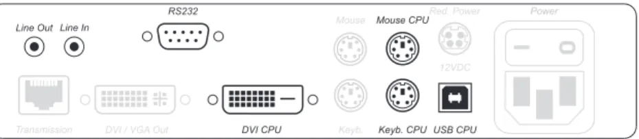
DVI CPU: Connect the digital video output of the computer to this interface. For this purpose, use the DVI-D-M/M-2 cable.
USB CPU: Connect the USB interface of the computer to this interface. For this pur-pose, use the USB-AM/BM-2 cable.
Keyb. CPU: Connect the PS/2 keyboard interface of the computer to this interface. For this purpose, use the PS/2-M/M-2 cable (purple plugs).
Mouse CPU: Connect the PS/2 mouse interface of the computer to this interface. For this purpose, use the PS/2-M/M-2 cable (green plugs).
Additional interfaces of the variants DVIVision-AR and -ARU:
Line Out: Connect the Line-In interface of the computer to this interface. For this purpose, use the Audio-M/M-2 cable.
Line In: Connect the Line-Out interface of the computer to this interface. For this purpose, use the Audio-M/M-2 cable.
RS232: Connect the nine-pole serial interface of the computer to this interface. For this purpose, use the RS232-M/F-2 cable.
Figure 1: Interfaces to connect the computer to the computer module
The mouse and keyboard signals of both consoles can either be transmitted to the computer through the USB interface USB CPU or through the PS/2 interfaces Mouse CPU and Keyb. CPU.
Installation
Optional: Connecting the local console
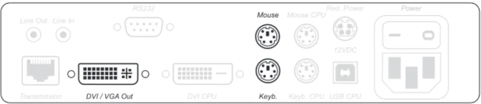
DVI/VGA Out: Connect the monitor of the local console to this interface.
If the monitor only provides an analog VGA input, connect the DVI-I-HD15F adapter to this interface. Afterwards, connect the monitor’s VGA cable to the adapter. Keyb.: Connect the keyboard of the local console to this interface.
Mouse: Connect the mouse of the local console to this interface.
Connections for data transmission and power supply
Transmission: Connect the category 5e (or better) twisted pair cable, which is availa-ble as accessories, to this interface. Connect the other end of the caavaila-ble to the respec-tive interface ofthe user module.
Power: Insert the supplied PowerCable-2 Standard IEC cable.
Red. Power: The Power-Set 12/Type 2 power pack can optionally be connected using this plug. Through this, a second, redundant power supply of the computer module is achieved.
Figure 2: Interfaces to connect the local console to the computer module
Installation
Additional interfaces of the multi-channel variants
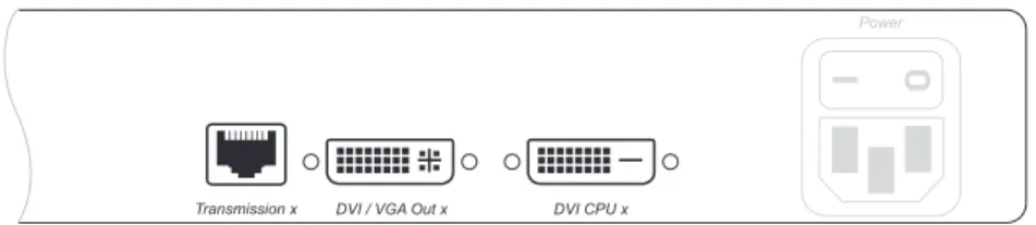
Transmission x: Connect the category 5e (or better) twisted pair cable, which is avail-able as accessories, to this interface. Connect the other end of the cavail-able to the respec-tive interface of the workstation module.
DVI/VGA Out x: Connect the monitor of the local console to this interface.
If the monitor only provides an analog VGA input, connect the DVI-I-HD15F adapter to this interface. Afterwards, connect the monitor’s VGA cable to the adapter. DVI CPU x: Connect the digital video output of the computer to this interface. For this purpose use the DVI-D-SL-M/M-2 cable.
Figure 4: Additional interfaces of the multi-channel variant at the computer module
For each added video channel, the multi-channel variants of the computer module are additionally provided with the interfaces Transmission, DVI/VGA Out and DVI CPU.
The interfaces of each channel are located next to each other. The descriptions of the interfaces are provided with the number of the channels.
Installation
Installing the user module (DVIVision-CON)
Connecting the remote console
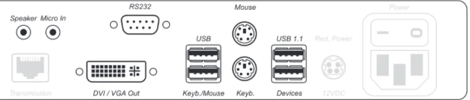
DVI/VGA Out: Connect the console monitor to this interface.
If the monitor only provides an analog VGA input, connect the DVI-I-HD15F adapter to this interface. Afterwards, connect the monitor’s VGA cable to the adapter.
USB Keyb.: Connect the USB keyboard to this interface. USB Mouse: Connect the USB mouse to this interface. Keyb.: Connect the PS/2 keyboard to this interface. Mouse: Connect the PS/2 mouse to this interface.
Additional USB interfaces of the variants DVIVision-ARU and -U:
USB 1.1 Devices: Any USB device can be connected with these interfaces. Two USB interfaces are located on the back panel of the device, another two can be found on the front panel. The data rate of the interfaces is 12 MBit/s (USB 1.1).
The USB devices are provided to the computer module (DVIVision-CPU) which is connected to the computer.
Additional interfaces of the variants DVIVision-AR and ARU: Speaker: Connect the speakers of the console to this interface.
Micro In: If desired, connect the microphone of the console to this interface. RS232: Connect the serial device to this interface.
The serial device ist provided to the computer that is connected to the computer module (DVIVision-CPU).
Figure 5: Interfaces to connect the user console to the user module
Both mouse and keyboard of the remote console can either be connected as a PS/2 device or as a USB device.
Installation
Connections for data transmission and power supply
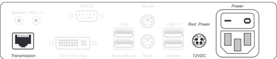
Transmission: Connect the category 5e (or better) twisted pair cable, which is availa-ble as accessories, to this interface. Connect the other end of the caavaila-ble to the respec-tive interface of the computer module.
Power: Insert the supplied PowerCable-2 Standard IEC cable.
Red. Power: The Power-Set 12/Type 2 power pack can optionally be connected using this plug. Through this, a second, redundant power supply of the user module is achieved.
Additional interfaces of the multi-channel variants
Transmission x: Connect the category 5e (or better) twisted pair cable, which is avail-able as accessories, to this interface. Connect the other end of the cavail-able to the respec-tive interface of the computer module.
DVI/VGA Out x: Connect the monitor of the console to this interface.
If the monitor only provides an analog VGA input, connect the DVI-I-HD15F adapter to this interface. Afterwards, connect the monitor’s VGA cable to the adapter. Figure 6: Interfaces for data transmission and power supply
Figure 7: Additional interfaces of the multi-channel variants at the user module
For each additional video channel, the multi-channel variants of the user module are additionally provided with the interfaces Transmission and DVI/VGA Out.
The interfaces of each channel are located next to each other. The interfaces are provided with the numbers of the channels.
Initiation
Initiation
After the proper installation, the DVIVision system can be immediately put into operation.
Mind the following activation sequence while initiating the system:
1. Turn on the user module (DVIVision-CON) at the switch that is located above the Power socket.
2. Turn on the computer module (DVIVision-CPU) at the switch that is located above the Power socket.
3. Turn on the computer that is connected to the computer module.
After the DVIVision system has been turned on, the LEDs on the front panel of both the computer module and the user module signal the system’s operating status. For further advices on this topic, also see the chapter Status displays on page 36 ff.
The recommended activation sequence ensures that the DVIVision system is able to read out the features of the connected monitor and to transmit them to the com-puter (see DDC transmission with cache function on page 35).
Operation
Operation
The computer connected to the computer module (DVIVision-CPU) can be oper-ated at the remote console of the user module as well as at the local console of the computer module.
After having initiated both consoles, they are enabled to operate the computer.
Concurrent operation of the DVIVision system
If a user carries out a keyboard or a mouse input, the DVIVision system automati-cally locks the input devices of the concurrent console. The lock is lifted if no inputs are made at the active console during the adjusted timing of the automatic input lock (default: 1 second).
After the automatic input lock has been lifted, both consoles are again able to operate the computer.
As an alternative to operate the computer concurrently through the consoles, the exclusive operation (see below) can also be activated.
Related topics:
Timeout of the automatic input lock on page 21
Changing the videomode of the user consoles on page 23
Exclusive operation of the DVIVision system
For operating the DVIVision system exclusively, the function Authorising permanent activation of input lock can be activated in the setup menu.
If this function is turned on, the user of the DVIVision system can activate the exclu-sive operation by pressing the key combination Hotkey + Print Screen (default: Ctrl + Print Screen).
After having pressed this key combination, the input devices of the concurrent con-sole are deactivated. By pressing the key combination again at the concon-sole where the permanent input lock has been activated, users at both consoles are again able to operate the DVIVision system.
After the permanent input lock has been activated at one console, the Scroll LEDs are blinking on the keyboards of both consoles.
Related topics:
Authorising permanent activation of input lock on page 22
Changing the videomode of the user consoles on page 23
In the default setting, the monitors of both the remote and the local console of the DVIVision system always display the same picture at the same time – independ-ently from the input lock.
The paragraph Changing the videomode of the user consoles on page 23 explains how this setting can be changed.
Configuration
Configuration
The configuration of the DVIVision system can be changed by the user in both the setup mode and the setup menu:
The setup mode is activated through a console keyboard. The configuration can be changed by pressing special setup keys.
As an alternative, the setup menu is provided. The configuration can be changed by using a terminal emulation program and a supplied data cable.
Overview of the functions and the default settings
The following table provides an overview of the configurable functions of the DVIVision system. In addition, the default settings and references to detailed func-tion descripfunc-tions are listed.The following pages provide a detailed description of how to operate the setup mode and the setup menu.
The configurable functions of the DVIVision system are described in detail on page 17 ff.
Some functions of the DVIVision system can only be carried out in either the setup mode or the setup menu. Note the advices referring to this on the following pages.
Function Standard setting Page
Activating or deactivating the hotkey delay turned on 17 Using single or double hotkeys single hotkeys 18
Changing the single hotkey Ctrl 19
Changing the double hotkey Ctrl + Shift 20 Timeout of the automatic input lock 1 second 21 Authorising permanent activation of input lock turned off 22 Changing the videomode of the user consoles turned on 23 Activating or deactivating the video compression turned on 24 Support for multimedia or Sun special keys PC Multimedia 25
Support for special keyboards turned off 27
Changing the scancode set of a PS/2 keyboard scancode set 2 28
Activating or resetting a PS/2 mouse 29
Displaying the system’s status information 30
Configuration
Changing the configuration
The configuration can either be changed in the setup mode or in the setup menu. The descriptions of the configurable functions on the following pages include ins-tructions on how to configurate both the setup mode and the setup menu.
Using the setup mode
The setup mode can be activated through the keyboard of a console at any time. After the setup mode has been activated, the configuration of the DVIVision system can be changed with various setup keys.
How to activate the setup mode:
Press the key combination Hotkey + Backspace (default: Ctrl + Backspace) at the same time to activate the setup mode.
The control LEDs NUM, and Scroll are blinking simultaneously if the setup mode has been successfully activated. Additionally, the yellow user LED at both the com-puter module and the user module is blinking.
Now you can perfom a setup function. How to perform a setup function:
After the setup mode has been activated, press one of the setup keys that are described on the following pages.
How to end the setup mode without performing a function:
Press ESC to end the setup mode.
After the call of the setup mode, only one setup function can be carried out. If you want to perform several functions, you have to restart the setup mode after having performed a function.
In the default settings, the key combination to activate the setup mode has to be pressed for seven seconds.
After the first call of the setup mode, the hotkey delay can be turned off by pres-sing the setup key 8 (see page 17).
Configuration
Using the setup menu
The setup menu enables you to comfortably view and edit the configuration of the DVIVision system. In contrast to the setup mode, it is possible to edit several set-tings within one session.
For using the setup menu, start any terminal emulation program on a computer (for example HyperTerminal or PuTTY). The computer on which the terminal emulation program is installed, is connected to the Service socket of the computer module or the user module with supplied data cable.
How to establish a connection in the terminal emulation program:
Start any terminal emulation program (for example HyperTerminal or PuTTY).
Collect the following data to establish a connection to the DVIVision system:
Bits per second: 38400
Data bits: 8
Parity: None
Stop bits: 1
Flow control: None
Use the supplied data cable to connect the computer to the Service socket on the front panel of the computer module or the user module.
How to start the setup menu:
Start the terminal emulation program.
Load the connection settings of the setup menu and establish the connection.
Press the Enter key in the terminal emulation program.
As soon as the connection has been succesfully established, the setup menu is dis-played within the terminal emulation program (see figure on page 16).
How to end the setup menu:
Configuration
Operating the setup menu
The setup menu lists all settings of the DVIVision system in tabular form:
The active setting of the various functions is displayed in the right column. If this func-tion contains a sub-dialogue, it is displayed with three dots [...] in the right column. How to operate the setup menu:
Select the desired menu item with the arrow keys of the keyboard. The active row is marked with angular arrows.
The settings of the menu items that are displayed in the right column can be chan-ged by pressing the Space key (repeatedly).
If you have selected a menu item that includes a sub-dialogue, press the Enter key to open it.
Setup Menu for DVIVision-CPU
Show System Info ...
Show Version Info ...
Show Line Info ...
Show Temperature Info ...
Hotkey: Ctrl
Double Hotkey: No
Hotkey Delay: YES
Set System Defaults ...
Scancode Set CPU: 2
Scancode Set CON: 2
PS/2 Keyboard Type CPU: Standard PS/2 Keyboard Type CON: Standard
USB Keymode: PC Multimedia
Video Compression: On
Permanent Access CPU: No
Permanent Access CON: No
Videomode CPU: Always On
Videomode CON: Always On
Timeout: 1 s
Configuration
Configurational settings
Activating or deactivating the hotkey delay
In the default settings of the DVIVision system, the key combination Hotkey + Backspace (default: Ctrl + Backspace) has to be pressed for seven seconds to start the setup mode. If you want to start the setup mode directly after having pres-sed the key combination, the hotkey delay can be deactivated.
How to (de)activate the hotkey delay:
set
up mode
1. Press the key combination Hotkey + Backspace (default: Ctrl + Backspace) to activate the setup mode. If the hotkey delay is active, press the key combi-nation for seven seconds.
2. Press one of the setup keys listed below to (de)activate the hotkey delay: 7 activates the hotkey delay
8 deactivates the hotkey delay
set
u
p
menu
1. Establish the connection to the DVIVision system through the terminal emulation program.
2. Use the arrow keys to select the row Hotkey Delay.
3. Press the Space key (repeatedly) to (de)activate the hotkey delay: Yes activates the hotkey delay
No deactivates the hotkey delay 4. Press the S key to save the settings.
Configuration
Using single or double hotkeys
The number of “free” key combinations is possibly narrowed if many application programs with hotkeys are operated on one computer or if different G&D devices are used in one cascade.
In such a case, a set of key combinations that does not collide with other porgrams or cascaded G&D devices can be used by applying double hotkeys.
How to activate the use of single or double hotkeys:
After the switching, the active hotkey is being converted into a double hotkey (or vice versa):
Related topics:
Changing the single hotkey on page 19
Changing the double hotkey on page 20
set
u
p
mode
1. Press the key combination Hotkey + Backspace (default: Ctrl + Backspace) to activate the setup mode. If the hotkey delay is active, press the key combi-nation for seven seconds.
2. Press one of the setup keys listed below to activate the use of single or double hotkeys:
S use of single hotkeys A use of double hotkeys
set
u
p m
enu 1. Establish the connection to the DVIVision system through the terminal emulation program. 2. Use the arrow keys to select the row Double Hotkey.
3. Press the Space key (repeatedly) to activate the use of single or double hotkeys: No use of single hotkeys
Yes use of double hotkeys 4. Press the S key to save the settings.
Single hotkey Double hotkey
Ctrl Ctrl + Shift
Alt Alt + Shift
Alt Gr Alt Gr + Ctrl
Win Win + Ctrl
Configuration
Changing the single hotkey
The hotkey has to be pressed in combination with the Backspace key to call the setup mode of the DVIVision system.
If an application program or another G&D device within the cascade uses the same hotkey, the hotkey can be changed.
How to change the current hotkey:
Related topic:
Using single or double hotkeys on page 18
The single hotkey Ctrl is preset in the delivery status.
set
u
p mode
1. Press the key combination Hotkey + Backspace (default: Ctrl + Backspace) to activate the setup mode. If the hotkey delay is active, press the key combi-nation for seven seconds.
2. Press one of the setup keys listed below to activate a certain hotkey: Ctrl activates the hotkey Ctrl
Alt activates the hotkey Alt Alt Gr activates the hotkey Alt Gr Win activates the hotkey Win Shift activates the hotkey Shift
set
u
p m
enu 1. Establish the connection to the DVIVision system through the terminal emulation program. 2. Use the arrow keys to select the row Hotkey.
3. Press the Space key (repeatedly) to activate a certain hotkey: Ctrl activates the hotkey Ctrl
Alt activates the hotkey Alt Alt Gr activates the hotkey Alt Gr Win activates the hotkey Win Shift activates the hotkey Shift 4. Press the S key to save the settings.
Configuration
Changing the double hotkey
If you have activated the use of double hotkeys (see page 18), the double hotkey has to be pressed in combination with the Backspace key to call the setup mode of the DVIVision system.
The double hotkey can be changed if an application program or another G&D device within the cascade uses the same double hotkey.
How to change the current double hotkey:
Related topic:
Using single or double hotkeys on page 18
set
u
p
mode
1. Requirement: activation of the double hotkeys (see page 18).
2. Press the key combination Hotkey + Backspace (default: Ctrl + Backspace) to activate the setup mode. If the hotkey delay is active, press the key combi-nation for seven seconds.
3. Press one of the setup keys listed below to activate the desired double hotkey: Ctrl activates the double hotkey Ctrl + Shift
Alt activates the double hotkey Alt + Shift Alt Gr activates the double hotkey Alt Gr + Ctrl Win activates the double hotkey Win + Ctrl Shift activates the double hotkey Shift + Win
set
u
p m
enu 1. Requirement: activation of the double hotkeys (see page 18).
2. Establish the connection to the DVIVision system through the terminal emulation program.
3. Use the arrow keys to select the row Hotkey.
4. Press the Space key (repeatedly) to activate the desired double hotkey: Ctrl + Shift activates the double hotkey Ctrl + Shift
Alt + Shift activates the double hotkey Alt + Shift Alt Gr + Ctrl activates the double hotkey Alt Gr + Ctrl Win + Ctrl activates the double hotkey Win + Ctrl Shift + Win activates the double hotkey Shift + Win 5. Press the S key to save the settings.
Configuration
Timeout of the automatic input lock
As soon as a user carries out an input through keyboard or mouse, the DVIVision system automatically locks the input devices of the concurrent console. The lock is lifted if no input is being made at the active console within the adjusted timing of the input lock (default: 1 second).
After the lock has been lifted, both users can operate the computer again. The timing of the input lock can be adjusted from 1 to 90 seconds. How to set the timout of the automatic input lock:
Related topic:
Exclusive operation of the DVIVision system on page 12
This function can only be (de)activated in the setup menu.
se
tu
p men
u 1. Establish the connection to the DVIVision system through the terminal emulation program.
2. Use the arrow keys to select the row Timeout.
3. Use the numerical keys of the keyboard to input the desired value and press the Enter key.
Configuration
Authorising permanent activation of input lock
If no inputs are being made at the active console during the adjusted timeout of the automatic input lock (default: 1 second), the default settings of the DVIVision system also permit to operate the system from the other console.
If the function Authorising permanent activation of input lock is activated in the setup menu, the users of the DVIVision system are enabled to permanently activate the input lock with the key combination Hotkey + Print Screen (default: Ctrl + Print Screen).
After having pressed this key combination, the input devices of the concurrent con-sole are deactivated. By pressing the key combination again at the active concon-sole, both consoles are again able to operate the DVIVision system after the automatic input lock has elapsed.
When the permanent input lock has been activated at one console, the Scroll LEDs are blinking on the keyboards of both users.
How to (de)activate the Authorising permanent activation of input lock function:
Related topics:
Timeout of the automatic input lock on page 21
Changing the videomode of the user consoles on page 23
This function can only be (de)activated in the setup menu.
set
u
p
menu
1. Establish the connection to the DVIVision system through the terminal emulation program.
2. Select the row Permanent Access CPU with the arrow keys, if you want to change this setting for the local console.
Select the row Permanent Access CON with the arrow keys, if you want to change this setting for the remote console.
3. Press the Space key (repeatedly) to (de)activate this function: Yes activation of the permanent input lock possible No activation of the permanent input lock not possible
Configuration
Changing the videomode of the user consoles
In the standard configuration of the DVIVision system, the computer’s video signal is output at the monitor of the active console as well as at the monitor of the concur-rent console.
By applying the function Changing the videomode of the user consoles, the video signal at the concurrent user’s monitor can be turned off automatically as soon as an input is made by a user.
If the user has finished his inputs, the monitor at the concurrent console is reactiva-ted after the automatic input lock has elapsed or the permanent input lock has been deactivated.
How to (de)activate the video signal at the concurrent user console:
Related topics:
Timeout of the automatic input lock on page 21
Authorising permanent activation of input lock on page 22
This function can only be (de)activated in the setup menu.
se
tu
p
m
enu 1. Establish the connection to the DVIVision system through the terminal emulation program. 2. Select Videomode CPU with the arrow keys, if you want to change this setting for
the local console.
Select Videomode CON with the arrow keys, if you want to change this setting for the remote console.
3. Press the Space key (repeatedly) to (de)activate the video signal at the con-current console:
Always On always display the video signal of the concurrent user Switch Off switch off video signal for inputs of the other user
Configuration
Activating or deactivating the video compression
The video signal usually is transmitted between the computer module and the user module in a compressed way. Due to this compression, the picture on the console monitors are normally displayed lossless and judder free.
Under certain conditions, moving pictures can cause a special tearing effect on the monitors of the remote console. In this case, the monitor image consists of two sub-sequent frames that are partly displayed:
The lower part of the picture shows a part of the old frame, the upper part shows a part of the new frame. At the point where both frames touch, the picture appears to be “torn“.
In this case, deactivate the video compression to display the moving picture without the tearing effect.
How to (de)activate the video compression:
This function can only be (de)activated in the setup menu.
Note: The missing video compression causes a small juddering at the monitor of
the remote console.
set
u
p m
enu 1. Establish the connection to the DVIVision system through the terminal emulation program. 2. Use the arrow keys to select the row Video Compression.
3. Press the Space key (repeatedly) to (de)activate the video compression: Enabled activates the video compression
Disabled deactivates the video compression 4. Press the S key to save the settings.
Configuration
Support for multimedia or Sun special keys
Various manufacturers have added special keys to the standard keyboards.
Some keyboards are provided with multimedia keys through which it is possible to comfortably operate special multimedia functions of the computer. For example, the keyboard of the Apple Mac mini is provided with a key to open the DVD drive. Compared to standard keyboards, Sun desktops and servers are provided with sepa-rate keys (Solaris Shortcut Keys) to opesepa-rate special system functions. After the key-board mode for Sun desktops and servers has been activated, the Solaris Shortcut Keys can be used at the workstation. If the workstation only provides a standard keyboard, several key combinations can be applied to emulate the Solaris Shortcut Keys (see page 26).
To be able to use special keys of such keyboards, several USB Keymodes are provided. How to (de)activate the support for multimedia- or Sun special keys:
The support of multimedia or Sun special keys can only be changed in the setup menu.
set
u
p m
enu 1. Establish the connection to the DVIVision system through the terminal emulation program. 2. Use the arrow keys to select the row USB Keymode.
3. Press the Space key (repeatedly) to select between the following settings: PC Multimedia activates the support for multimedia keys
SUN German Sun keyboard (German layout)
SUN US Sun keyboard (American layout)
PC Standard deactivates the support for special keys 4. Press the S key to save the settings.
5. Optional: If you have changed the keyboard layout of the Sun keyboard, the
Configuration
If a Sun keyboard is connected to the workstation, it is possible to use the Solaris Shortcut Keys of this keyboard after their support has been activated. Even when using a standard keyboard, these functions can be performed by applying the key combinations listed below:
Key combination Solaris Shortcut Key of the Sun keyboard
Ctrl + Alt + F2 Again Ctrl + Alt + F3 Props Ctrl + Alt + F4 Undo Ctrl + Alt + F5 Front Ctrl + Alt + F6 Copy Ctrl + Alt + F7 Open Ctrl + Alt + F8 Paste Ctrl + Alt + F9 Find Ctrl + Alt + F10 Cut Ctrl + Alt + F11 Help Ctrl + Alt + F12 Mute
Ctrl + Alt + NUM+ Loud
Ctrl + Alt + NUM- Quiet
Ctrl + Alt + NUM* Compose
Ctrl + Alt + Pause Shutdown
Configuration
Support for special keyboards
The DVIVision system supports the special functions of the keyboards PixelPower Clarity (blue) and SKIDATA1.
If you want to apply such a keyboard, activate its support through the DVIVision system.
How to turn on or turn off the support for special keyboards: Support for special keyboards can only be activated in the setup menu.
set
u
p
menu
1. Establish the connection to the DVIVision system through the terminal emulation program.
2. Select the row PS/2 Keyboard Type CPU with the arrow keys, if you want to change this setting for the local console.
Select the row PS/2 Keyboard Type CON with the arrow keys, if you want to change this setting for the remote console.
3. Press the Space key (repeatedly) to to (de)activate the support for a special keyboard:
PixelPower Blue activates the support of the PixelPower Blue keyboard
SKIDATA1 activates the support of the SKIDATA1 keyboard
Standard deactivates the support of PixelPower keyboards 4. Press the S key to save the settings.
Configuration
Changing the scancode set of a PS/2 keyboard
If a key is pressed on the PS/2 keyboard, the keyboard processor sends a data packet that is called scancode. There are two common scancode sets (sets 2 and 3) that con-tain different scancodes.
In the standard configuration the DVIVision system interprets all inputs of a PS/2 keyboard with the scancode set 2.
If the pipe (“|”) cannot be input or if the arrow keys of the keyboard do not function as expected, it is recommended to switch to scancode set 3.
How to change the setting of the scancode set:
se tu p m o d
e 1. Press the key combination Hotkey + Backspace (default: Ctrl + Backspace) to activate the setup mode. If the hotkey delay is active, press the key combi-nation for seven seconds.
2. Press one of the setup keys listed below to activate a certain scancode set: 2 activates the scancode set 2 for PS/2 keyboard inputs
3 activates the scancode set 3 for PS/2 keyboard inputs
3. Turn off the DVIVision system and then turn it back on again. After you have turned the DVIVision system back on, the keyboard is initialised and the selected scancode set is applied.
se
tu
p
m
enu 1. Establish the connection to the DVIVision system through the terminal emulation program. 2. Select the row Scancode Set CPU with the arrow keys, if you want to change
this setting for the local console.
Select the row Scancode Set CON with the arrow keys, if you want to change this setting for the remote console.
3. Press the Space key (repeatedly) to activate a certain scancode set: 2 activates the scancode set 2 for PS/2 keyboard inputs 3 activates the scancode set 3 for PS/2 keyboard inputs 4. Press the S key to save the settings.
5. Turn off the DVIVision system and then turn it back on again. After you have turned the DVIVision system back on, the keyboard is initialised and the selected scancode set is applied.
Configuration
Activating or resetting a PS/2 mouse
Unlike USB mouse devices, PS/2 mouse devices do not support the hot plug tech-nology. You can therefore insert the PS/2 plug during operation but it may be pos-sible that the computer does not detect the input device.
To activate or reset the PS/2 mouse, a special command can be send to the compu-ter through the DVIVision system.
Since the commands differ depending on the used mouse type and the installed ope-rating system, four different setup keys are provided.
How to activate or reset a PS/2 mouse:
A PS/2 mouse can only be activated or reset in the setup mode.
set
u
p mode
1. Press the key combination Hotkey + Backspace (default: Ctrl + Backspace) to activate the setup mode. If the hotkey delay is active, press the key combi-nation for seven seconds.
2. Press one of the following setup keys to activate or reset the PS/2 mouse: M activates the PS/2 mouse of a Linux computer
I activates the PS/2 wheel mouse of a Linux computer
E activates the PS/2 wheel mouse with additional keys of a Linux computer R resets the PS/2 mouse interface of a Windows computer
Configuration
Displaying the system’s status information
Detailed status information of the DVIVision system can be viewed in the setup menu. Therefore, the setup menu provides entries that are described in the following. Show System Info: Lists different information (number of video channels, connection type of the input devices, etc.) about the DVIVision system.
Show Version Info: Shows version numbers of the different components of the DVIVision system.
Show Line Info: Shows features and data of the transmission cables.
The keys R and L enable switching between the features of the remote and the local module. In this context, the local module is always the module the data cable is con-nected to.
With multi-channel devices, the different channels can be switched by pressing the keys 1 to 5.
Show Temperature Info: Shows temperature inside of the module.
The keys R and L enable switching between the features of the remote and the local module. In this context, the local module is always the module the data cable is con-nected to.
How to display the status information in the terminal emulation program: The status information can only be viewed in the setup menu.
The row Console Access shows, which console (CPU or CON) currently operates the DVIVision system and if the permanent access (display in setup menu: Permanent) to the DVIVision system is activated.
set
u
p menu
1. Establish the connection to the DVIVision system through the terminal emulation program.
2. Use the arrow keys to select one of the rows mentioned above.
3. Press the Enter key, to display the information in the terminal emulation program.
The displayed information can be updated by pressing the U key. 4. Press the Q key to return to the main menu.
Configuration
Resetting the default settings
This function resets the default settings of the DVIVision system. By performing this function, the default settings of the DVIVision system mentioned on page 13 are reactivated.
How to reset the default settings:
set
u
p mode
1. Press the key combination Hotkey + Backspace (default: Ctrl + Backspace) to activate the setup mode. If the hotkey delay is active, press the key combi-nation for seven seconds.
2. Press the setup key listed below to reset the default settings: D resets the default settings
set
u
p
menu
1. Establish the connection to the DVIVision through the terminal emulation program.
2. Use the arrow keys to select the row Set System Defaults. 3. Press the Enter key to reset the default settings.
4. Confirm the now appearing security query with the Enter key. You can can-cel the function by pressing the Q key.
Continuative information
Continuative information
Recommendations for the twisted pair cable
The transmission of all signals of the DVIVision system is carried out through one twisted pair cable (category 5e or better).
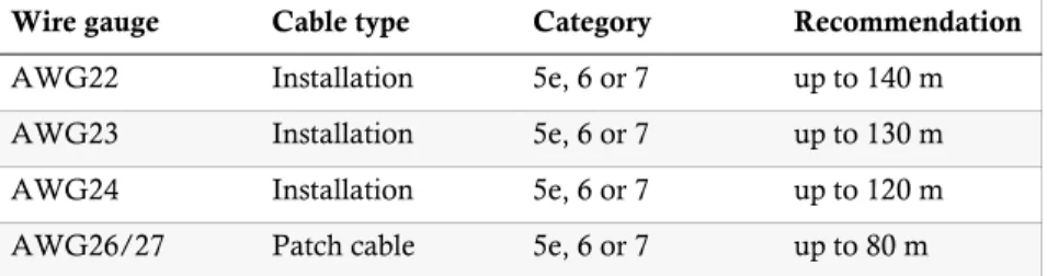
The data transmission is reliable over a distance of at least 100 metres using a regu-lar standard twisted pair cable (category 5e or better). The distance that can actually be achieved depends on the quality of the used cable. High-quality S-STP cables with an AWG22 wire gauge coding can bridge a distance of up to 140 metres. Patch cables with an AWG26 wire gauge coding can only bridge a maximum of 80 metres.
To ensure reliable operation even in environments with interference, installation cables with at least AWG24 coding have to be used for lengths over 80 metres.
The following cables achieved the best results during test operation:
up to 140 metres: Kerpen MegaLine G12-150 S/F AWG22
up to 100 metres: G&D K-C5-HR (see Order numbers on page 45)
up to 80 metres: Dätwyler Uninet flex 4P, AWG26, S-STP
The connection of several segments using patch panels and connection ports is permitted. However, connections through active network components such as network switches, hubs or repeaters are not permitted.
Wire gauge Cable type Category Recommendation
AWG22 Installation 5e, 6 or 7 up to 140 m
AWG23 Installation 5e, 6 or 7 up to 130 m
AWG24 Installation 5e, 6 or 7 up to 120 m
AWG26/27 Patch cable 5e, 6 or 7 up to 80 m Table 2: Recommended cable lengths depending on the wire gauge
The lengths that are mentioned in the table above must be interpreted as the sum of all segments between the devices.
Continuative information
USB and PS/2 signals of the variants -ARU and -U
If you use a variant of DVIVision that supports USB devices, it is necessarily required to connect the USB CPU interface of the computer module (DVIVision-CPU) with the USB interface of the computer. The data of the USB devices are transmitted to the computer through this interface.The signals of keyboard and mouse are also transmitted through this USB connection. If you prefer to transmit the signals of keyboard and mouse through the PS/2 inter-faces, connect the interfaces Mouse CPU and Keyb. CPU with the PS/2 interfaces of the computer.
Supporting any resolution
In principle, the DVIVision system supports all resolutions that can be transmitted through a single link interface according to the DVI specification 1.0.
This restriction mainly affects the pixel rate, which can reach from 25 MHz to 165 MHz. Therefore, resolutions between 640 x 480 pixels at 60 Hz and 1600 x 1200 pixels at 60 Hz are possible for the common timing standards by VESA DMT and VESA SMT. 1920 x 1200 pixels at 60 Hz is transmitted according to VESA CVT-RB. Almost any refresh rate and resolution within the technical constraints are possible. The available display modes are largely dependent on the graphics card, the gra-phics driver, the operating system and the connected monitor.
The video data that are transmitted from the computer to the computer module (DVIVision-CPU) are transferred to the monitor of the remote console with the same timing. The signal’s frequency and display position at the computer module therefore correspond to those of the graphics output.
Note: While generating the video signal, some graphics cards differentiate
between digital and analog output. Such graphics cards generate digitally output image signals with partly non-standardised timings. Such timings do not comply with the monitor’s default to reduce the frequencies of the digital signals.
Normally, this does not affect the DVIVision system and the digitally con-nected displays. Due to the non-standardised timing, analog monitors might not be able to display the image size and the image position properly.
Continuative information
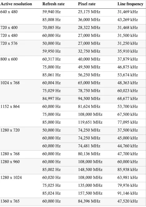
The following table shows examples of some possible display modes:
Active resolution Refresh rate Pixel rate Line frequency
640 x 480 59,940 Hz 25,175 MHz 31,469 kHz 85,008 Hz 36,000 MHz 43,269 kHz 720 x 400 70,085 Hz 28,322 MHz 31,468 kHz 720 x 480 60,000 Hz 27,000 MHz 31,500 kHz 720 x 576 50,000 Hz 27,000 MHz 31,250 kHz 59,950 Hz 32,750 MHz 35,910 kHz 800 x 600 60,317 Hz 40,000 MHz 37,879 kHz 75,000 Hz 49,500 MHz 46,875 kHz 85,061 Hz 56,250 MHz 53,674 kHz 1024 x 768 60,004 Hz 65,000 MHz 48,363 kHz 75,029 Hz 78,750 MHz 60,023 kHz 84,997 Hz 94,500 MHz 68,677 kHz 1152 x 864 60,000 Hz 81,624 MHz 53,700 kHz 75,000 Hz 108,000 MHz 67,500 kHz 85,000 Hz 119,651 MHz 77,095 kHz 1280 x 720 50,000 Hz 74,250 MHz 37,500 kHz 60,000 Hz 74,250 MHz 45,000 kHz 60,000 Hz 74,481 MHz 44,760 kHz 1280 x 768 60,000 Hz 80,136 MHz 47,700 kHz 1280 x 960 60,000 Hz 108,000 MHz 60,000 kHz 85,002 Hz 148,500 MHz 85,938 kHz 1280 x 1024 60,020 Hz 108,000 MHz 63,981 kHz 75,025 Hz 135,000 MHz 79,976 kHz 85,024 Hz 157,500 MHz 91,146 kHz 1360 x 765 60,000 Hz 84,396 MHz 47,520 kHz
Continuative information
DDC transmission with cache function
The DVIVision system supports Enhanced-DDC (Enhanced Display Data Channel) to read out the data from the monitor that is connected to the computer module (DVIVision-CON) and transmit them to the computer. This data includes informa-tion regarding the preferred resoluinforma-tion and the supported monitor frequencies. A cache function is integrated in the system so that the computer that is connected to the computer module (DVIVision-CPU) has access to the actual capabilities of the remote monitor already during the boot process. Even if the computer module or the user module are turned off or if the devices are not interconnected, the proper-ties of the most recently connected monitor or a default data block are provided in the DVIVision system.
The DDC information of the monitor are basically transmitted one-to-one. In case, the DVIVision system determines that the display cannot be read without errors or that the entries are invalid, the information are completed or corrected.
1360 x 768 49,892 Hz 69,000 MHz 39,564 kHz 59,799 Hz 84,750 MHz 47,720 kHz 1440 x 480 60,000 Hz 54,000 MHz 31,500 kHz 1440 x 576 50,000 Hz 54,000 MHz 31,250 kHz 1440 x 900 60,000 Hz 106,472 MHz 55,920 kHz 1400 x 1050 60,000 Hz 122,614 MHz 65,220 kHz 1600 x 900 60,000 Hz 118,998 MHz 55,920 kHz 1600 x 1024 60,000 Hz 136,358 MHz 63,600 kHz 1600 x 1200 60,000 Hz 162,000 MHz 75,000 kHz 1680 x 1050 60,000 Hz 147,136 MHz 65,220 kHz 1920 x 1080 50,000 Hz 148,500 MHz 56,250 kHz 60,000 Hz 148,500 MHz 67,500 kHz 1920 x 1200 59,950 Hz 154,000 MHz 74,038 kHz
Display modes that support interlace are not supported by the DVIVision system.
Active resolution Refresh rate Pixel rate Line frequency
Status displays
Status displays
The LEDs on the front panel of the computer module and the user module enable you to control the operational status of the DVIVision system at any time.
Computer module (DVIVision-CPU)
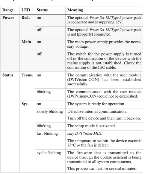
Range LED Status Meaning
Power Red. on The optional Power-Set 12/Type 2 power pack
is connected and is supplying 12V.
off The optional Power-Set 12/Type 2 power pack is not (properly) connected.
Main on The main power supply provides the neces-sary voltage.
off The switch for the power supply is turned off or the connection of the device with the mains supply is not established. Check the connection of the IEC cable.
Status Trans. on The communication with the user module
(DVIVision-CON) has been established successfully.
blinking The communication with the user module (DVIVision-CON) could not be established. Sys. on The system is ready for operation.
slowly blinking Defective internal communication. Turn off the device and then turn it back on. blinking The setup mode is activated.
fast blinking only DVIVision-MC3:
The temperature within the device exceeds 75°C or the fan is defect.
cyclic flashing The firmware that is transmitted to the device through the update assistent is being transmitted to all system components. This process can last for several minutes. Table 4: Status displays at the computer module (DVIVision-CPU)
Status displays
CPU Video on The incoming video signal of the computer
is being properly received.
blinking No stable video signal is being received or its quality is insufficent to be processed by the system.
K/M on The CPU input (PS/2 or USB) is active and ready for operation. A local keyboard was found.
off No voltage of the PS/2 interface or the USB bus.
blinking The CPU input (PS/2 or USB) is active and ready for operation. A local keyboard was not found.
flickering Keyboard and mouse inputs are being transmitted to the computer. The rhythm of the flickering is determined by the inputs of the user.
flashing The USB input of the computer module (DVIVision-CPU) is supplied with voltage. The computer is not (yet) ready for operation.
Range LED Status Meaning
Status displays
User module (DVIVision-CON)
Range LED Status Meaning
Power Red. on The optional Power-Set 12/Type 2 power pack
is connected and is supplying 12V.
off The optional Power-Set 12/Type 2 power pack is not (properly) connected.
Main on The main power supply provides the neces-sary voltage.
off The switch for the power supply is turned off or the connection of the device with the mains supply is not established. Check the connection of the IEC cable.
Status Trans. on The communication with the computer
mod-ule (DVIVision-CPU) has been established successfully.
blinking The communication with the computer mod-ule (DVIVision-CPU) could not be estab-lished.
Sys. on The system is ready for operation. slowly blinking Defective internal communication.
Turn off the device and then turn it back on. blinking The setup mode is activated.
fast blinking only DVIVision-MC3:
The temperature within the device exceeds 75°C or the fan is defect.
cyclic flashing The firmware that is transmitted to the device through the update assistent is being transmitted to all system components. This process can last for several minutes. Table 5: Status displays at the user module (DVIVision-CON)
Status displays
Console Video on The incoming video signal of the computer
module is being properly received at the user module.
blinking No image data are being received from the computer module (DVIVision-CPU). K/M on A keyboard (PS/2 or USB) was found.
blinking No keyboard (PS/2 or USB) was found.
Range LED Status Meaning
The expansion DVI-Power
The expansion DVI-Power
The expansion DVI-Power is provided for the variants DVIVision-AR and -ARU to control the buttons ATX-Power and Reset of the computer at the remote console.
Scope of delivery
The scope of delivery of DVI-Power expansion includes the following items:
G&D Power Card (slot card for installing in the computer)
connection cable to connect G&D Power Card and computer module
single-sided ready-made cable for connecting a panel to the user module
2 x two-pole connection cable (0,4 metres)
2 x two-pole extension cable (0,4 metres)
Functionality
The remote control of both the ATX-Power and the Reset function is carried out through a panel with two buttons. The panel is installed at the remote console.
The panel is connected to the system through a four-pole modular socket on the back panel of the user module (DVIVision-CON). The connection cable that is pro-vided in the scope of delivery has to be fixed to the panel (see Allocating the connection cable for the panel on page 43).
The panel for the operation of DVI-Power is not included in the scope of delivery of DVI-Power and has to be build by an expert.
The expansion DVI-Power
Installation guidelines
Installing the G&D Power Card into the computer
At first, install the G&D Power Card into the computer:
1. Take the manual of the computer and of the motherboard that is installed within the computer.
2. Open the casing of the computer to gain access to the expansion slots.
3. Assemble the G&D Power Card of the expansion DVI-Power to a free expansion slot of the computer.
Connecting the signal lines to the slot card
In the following, the signal lines ATX-Power and Reset of the motherboard are connected to the pin bar of the G&D Power Card (see figure). A further connection at the computer casing guarantees the use of these buttons.
Pwr-Sw: Connect the ATX-Power button cable of the
computer casing to these pins. In case the connection cable is not long enough, it can be extended with one of the extension cables.
Pwr-MB: Connect the pins you have written down before with the plug position of the ATX-Power button on the motherboard. Use one of the supplied connection cables for this purpose.
Res-Sw: Connect the Reset button cable of the computer casing to these pins. In case the connection cable is not long enough, it can be extended with one of the extension cables. Res-MB: Connect the pins you have written down before with the plug position of the Reset button on the motherboard. Use one of the the supplied connection cables for this purpose.
The G&D Power Card requires no slot at the motherboard of the computer. The installation only serves as assembly position for the ATX module at the back panel of the computer.
Write down the plug positions of the cables, which are leading from the ATX-Power button and the Reset but-ton of the casing to the motherboard. Afterwards,
dis-connect the cables. Res-MB
Res-Sw n. occupied Pwr-MB Pwr-Sw
The expansion DVI-Power
Connecting the G&D Power Card and the panel with DVIVision
Power Card: Connect this interface of the computer module to the interface on the back panel of the G&D Power Card
Control Panel: Connect the panel cable to this interface at the user module.
Operating the expansion DVI-Power
The functions of the panel buttons correspond to the functions of both the ATX-Power button and the Reset button at the computer casing.
Figure 8: Interface Power Card at the computer module (DVIVision-CPU)
Figure 9: Interface Control Panel at the user module (DVIVision-CON)
Depending on the BIOS setting of the computer, in some cases the panel’s ATX-Power button has to be pressed for five seconds to turn off the computer.
If necessary, check and change the respective setting within the BIOS of the com-puter to deactivate the delay.
The expansion DVI-Power
Allocating the connection cable for the panel
The connection cable that is provided in the scope of delivery has to be fixed to the panel. The following figure illustrates how the pins are assigned to the panel’s functions:
To switch one of the ATX-Power or Reset signals, the signal has to be conductively connected to the shared minus contact (pin 4):
Figure 10: Pin assignment to the functions of the panel
Figure 11: Basic circuit with buttons for ATX-Power and Reset 1 2 3 4 I1 SW1_ATXPWR# (Pin 1) I2 SW2_RESET# (Pin 3) - 0V (Pin 4) I1 SW1_ATXPWR# (Pin 1) I2 SW2_RESET# (Pin 3) - 0V (Pin 4)
Customer service
Customer service
Even after you have purchased our products you can count on G&D. Qualified sup-port in all areas of service is just as much a matter of course for us as the comprehen-sive advice provided by our sales force. For G&D, this is the foundation of an efficient partnership.
You can reach us
on Mondays to Thursdays from 8:00 am to 4:30 pm and
on Fridays from 7:30 am to 3:00 pm
under the telephone number +49 2739 8901-100. Requests by e-mail can be send to [email protected].
Technical data
Technical data
General features of the DVIVision series
Graphics Colour depth: 24 bits
Resolution @ 60 Hz: max. 1920 x 1200 pixels Resolution @ 85 Hz: max. 1280 x 1024 pixels Pixel rate: 25 MHz to 165 MHz Vertical frequency: 20 Hz to 100 Hz Horizontal frequency: 25 kHz to 130 kHz
Audio
(Variants -AR & -ARU) Transmission type:Resolution: transparent, bidirectional24 bit digital, stereo
Sampling rate 96 kHz Band width: 22 kHz
USB 1.1
(Variants -ARU & -U) Specification:Transmission type: USB 1.1transparent
Transmission rate: max. 12 Mbit/s
Supported devices: High-Power devices (up to 500 mA)
RS232
(Variants -AR &-ARU) Transmission type:Transmission rate: transparentmax. 115.200 bit/s
Transmitted signals: RxD, TxD, RTS, CTS, DTR, DSR, DCD
Update Mode: local service socket
Main power supply Type: internal power pack
Connection: IEC socket (IEC-320 C14) Voltage: AC100-240V/60-50Hz
Redundant
power supply Type:Connection: external power packminiDIN-4 power plug
Voltage: +12VDC/2,4A
Operation environment Temperature: +5 to +45 °C
Technical data
Specific features of the single-channel devices
DVIVision-CPUDVIVision-CON
Interfaces
for workstation Monitor:Keyboard/mouse: 1 x DVI-I socket2 x PS/2 socket
Interfaces
to computer Video:PS/2 keyboard/mouse: 1 x DVI-D socket2 x PS/2 socket
USB keyboard/mouse: 1 x USB-B socket Audio:
(only variants -AR & -ARU) 3,5-mm jack (Line In)3,5-mm jack (Line Out) USB 1.1:
(only variants -ARU & -U) shared signal transmission of the USB devices as well as of keyboard and mouse through USB-B plug
RS232:
(only variants -AR & -ARU) 1 x RS232 socket
Interfaces
for transmission to DVIVision-CON 1 x RJ45 socket
Interface
for update Service plug: 2,5-mm jack
Casing Material: anodised aluminium
Dimensions (W x H x D): 210 x 44 x 210 mm (desktop) 19” x 1 U x 210 mm (rackmount) Weight: approx plug. 1,3 kg
Interfaces
for workstation Monitor:PS/2 keyboard/mouse: 1 x DVI-I socket2 x PS/2 socket
USB keyboard/mouse: 2 x USB-A socket Audio:
(only variants -AR & -ARU) 3,5-mm jack (Speaker)3,5-mm jack (Micro In) USB 1.1:
(only variants -ARU & -U) 2 x USB-A socket
RS232:
(only variants -AR & -ARU) 1 x RS232 socket
Interface
for transmission to DVIVision-CPU 1 x RJ45 socket
Interface
for update Service plug: 2,5-mm jack
Casing Material: anodised aluminium
Dimensions (W x H x D): 210 x 44 x 210 mm (desktop) 19” x 1 U x 210 mm (rackmount) Weight: approx. 1,3 kg