Volume I, Issue III, July - 2014
An Improved Technique for Soft Clay
Stabilization Using
Electro Kinetic
Process
A.ARUTSELVAM,
Ph.D. Scholar, Techno Global University, Meghalaya. Mail ID: [email protected]
Abstract— The aim of this study was to evaluate the use of EKS as an effective method to strengthen soft clay soils. A detailed laboratory programme of work was conducted using the initial base model developed by Liaki (2006). This study was conducted in two stages using laboratory scale models, using inactive kaolinite clay. The test model using reusable Electro kinetic Geosythentics (EKG) developed at the Newcastle University to apply a constant voltage gradient of 50 V/m across a soil sample approximately 400 mm. The first stage involved testing of a ‘pure’ system with distilled water as the main pore electrolyte fluid supplied under zero hydraulic gradient conditions for periods of 3, 7 and 14 days. The second stage repeated test using calcium chloride and distilled water (CaCl-DW), DW and sodium silicate (DW-NaSiO) and CaCl-NaSiO, at the anode and cathode, respectively. Throughout both physical and chemical characteristics were measured. The data presented herein enables a fuller understanding of the mechanisms contributing to the improvements achieved and how effective monitoring through the use of relatively simple test, e.g. pH and Atterberg Limits, can be achieved. Specifically cation exchange was considered to be the main mechanism causing a significant increase in shear strength observed for the CaCl-DW system with the increase seen to be more uniform across the soil sample for a period up to 14 days. This was supported by results of Atterberg limits, pH, electrical conductivity and chemical concentrations. Precipitation and cation exchange are the main contributors to the increase of shear strength for the CaCl-NaSiO system after7 and 14 days treatment. However, precipitation of CSH gels has greater influence on the shear strength at the near proximity of cathode followed by cation exchange at the near proximity of anode and at the remainder of the soil sample.
Index Terms— anode, Precipitation, Atterberg limits, test model, cation exchange.
I. INTRODUCTION
Clays have unusual physicochemical properties chiefly because of the combined influenced of two factors. These are the high surface area and the electrical charge in the silicate structure of the clay mineral. The high surface area results from the small particle size and platy or elongate morphology of the minerals and the negative charge from ionic substitutions in the crystal structure. The charge is now thought to occur as discrete charge rather than as a uniform distribution over the surface (Gillot, 1987).
Particles exhibit properties characteristic of the colloidal state when they have sizes within range of about 50 to 2000 Å (Gillot, 1987). The surfaces of materials have distinctive Physico-chemical properties. In the interior of a solid, liquid or gas there is no imbalance in the forces acting on the atoms which are surrounded on all sides by a similar configuration of other atoms. The surface atoms of a solid or liquid however are pulled by attractive forces most strongly on
the side facing inward (Gillot, 1987). Water usually defines as a liquid composed of water molecules, H2O. However, some of the molecules disassociate themselves from the compound into hydrogen ions (H+) and hydroxyl ions (OH-). Water and soil particles interact with each other because, under ordinary circumstances, water molecules are strongly attracted to and absorbed on the soil particles surface. The negative electrical charge of the mineral attracts the cations, including the hydrogen ions disassociated from the water, to the surface of the mineral. The absorbed water molecules are more intense near the clay particles; with the intensity decreasing with an increase in distance from the clay particles with installation of vertical drains, and chemical stabilization as surface and deep soil treatment techniques.
Volume I, Issue III, July - 2014
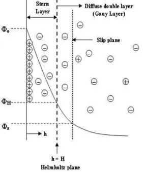
ionic charge, which is accumulated in the liquid near the particle surface (van Olphen, 1977). Several theories have been proposed for the ion distributions adjacent to the charged surfaces, which the Gouy-Chapman is the simplest and perhaps the most important one The Gouy-Chapman theory was improved by a more realistic double layer model which is the Stern model. The theory of the model assumes that some ions are tightly retained immediately next to the particle surfaces in a layer of specifically adsorbed water, the stern layer, and the double layer is diffuse beyond this layer. The double layer consists of two layers, Stern layer and Gouy layer (also called diffuse double layer), and the two layers are separated by the Helmholtz plane.
Hiemenz (1977) pointed out that generally, the thicker the diffuse layer the less the tendency for particles in suspension to flocculate and the higher the swelling pressure inexpensive soils. The diffuse layer becomes thinner when an increase in electrolyte concentration reduces the surface potential for the condition of constant surface charge.
Figure 1: Stern’s model and ions
distribution in the electric double layer
Clay absorbs cations of specific types and amounts under various environmental conditions such as temperature, pressure, pH, chemical and biological composition of the water. The total amount adsorbed balances the charge deficiency of the solid particles. Exchange reactions involved replacement of a part or all of the adsorbed ions of one type by ions of another type. The types of adsorbed cations depend on the depositional environment. For example, sodium and magnesium are dominant cations in marine clays since they are common in sea water. These exchange reactions may change the physical and physicochemical properties of the soil (Mitchell & Soga, 2005). Different samples of the same clay mineral give different values for cation exchange capacity so a range of value exists for the same mineral due to the
differences in structure and composition between samples. In addition, particle size also has an important effect. There are three sources of clay exchange capacity. Isomorphism substitution is the major source of clay exchange capacity, except for kaolin mineral. In clay minerals, however, some of the tetrahedral and octahedral spaces are occupied by cations other than those in the ideal structure. Common examples are aluminum in place of silicon, magnesium instead of aluminium, ferrous ion (Fe2+) for magnesium. This presence in an octahedral or tetrahedral position of a cation rather than that normally found, without change in crystal structure, is isomorphism substitution. In clay minerals, isomorphism substitution causes the clay minerals to obtain a net negative charge. Cations are attracted and held between the layers and on the surfaces and edges of the particles to preserve electrical neutrality.
Many of these cations are exchangeable cations because they may be replacing by cations of another type. The quantity of exchangeable cations is called the cation exchange capacity (CEC) and is usually expressed as mili equivalents (meq) 3 per 100 g of dry clay
The ease of cation replacement depends on the valence, ion size and relative abundance of different ion types. The lyotropic series generally states that higher valence cations can replace cations of lower valence and larger cations replace smaller cations of the same valence.
Na+ < Li+ < K+ < Rb+ < Cs+ < Mg2+ < Ca2+ < Ba2+ < Cu2+ < Al3+ < Fe3+ < Th4+
This series shows that the cations to the right will preferentially replace those to the left. Thus cation such as Ca2+ and Al3+ will replace those cations commonly found in clays. The cation commonly found in the diffuse double layer and the pore water are variously Sodium, potassium, calcium, magnesium and lithium, and in some cases higher order ions are also present. When cations of a higher valency and/or a larger ionic radius, such as calcium, silicon or aluminium, are introduced in significant concentrations, they saturate the solution and become absorbed at clay surface in preference to those ions originally present (Barker et
al., 2004). Valence is the most important factor
controlling ion selectivity, divalent ions being more strongly retained than mono valent ions and trivalent ions more strongly retained than divalent ions. Cations with larger non-hydrated radius or small hydrated radius have greater replacement power. However, it is possible to displace a cation of high replacing power such as Al3+, by one of low replacing power, such as Na+,by mass action, if the concentration in solution of the ion of low replacing power is high relative to that of the ion of higher replacing power .
II. LITERATURE SURVEY
Volume I, Issue III, July - 2014
properly. Therefore, irreversible thermodynamics may be used as a more comprehensive system of analysis when the simplifications employed in the direct observational approach are unacceptable. This method is a phenomenological, macroscopic theory that provides a basis for description of systems that are out of equilibrium in order to produce quantitative Prediction model. Electro kinetics is defined as the physicochemical transport of charge, action of charged Particles and effects of applied electric potentials on formation and fluid transport in porous media. Coupling between electrical and hydraulic flows can be responsible for different types of electro kinetic phenomena in soil. The electro kinetic phenomena include electro osmosis, streaming potential, electrophoresis and sedimentation potential (Mitchell & Soga, 2005). Further major phenomena reported by Acar & Alshawabkeh (1993) and Yeung (2006) that occur when an electric field is applied to any soil sample were electro migration. However, for the purposes of this research study, only electro osmosis, electro migration and electrophoresis will be discussed in the following sections, since they have been given the most attention in geotechnical engineering because of their practical value for transporting water and charged ions in fine grained soils.
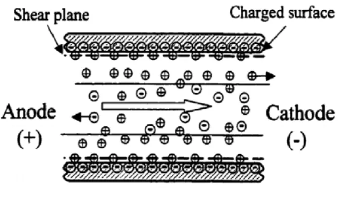
The electrical potential in the shear plane is defined as zeta potential. van Olphen (1977) stated that special mention should be given at this point to the zeta potential in the double layer at the interface between a particle that moves in an electric field and surrounding liquid. The shear plane is found at a small distance which is between charge surface and electrolyte solution and unknown distance from the surface of the particles. It should be noted that the location of the zeta potential cannot be measured by existing theories. This is one of the limitations of zeta potential concept as reported by van Olphen (1977).However, Shang (1997) has assumed the computed zeta potential located at 0.6 nm from the clay surface. The sign and magnitude of the zeta potential directly relate to the strength and direction of the electro osmosis flow.
Zeta Potential of Clay Minerals
The electrical potential in the shear plane is defined as zeta potential. van Olphen (1977) stated that special mention should be given at this point to the zeta potential in the double layer at the interface between a particle that moves in an electric field and surrounding liquid. The shear plane is found at a small distance which is between charge surface and electrolyte solution and unknown distance from the surface of the particles. It should be noted that the location of the zeta potential cannot be measured by existing theories.
Figure 2: Schematic of electro osmotic
flow between two charged surfaces
This is one of the limitations of zeta potential concept as reported by van Olphen (1977).However, Shang (1997) has assumed the computed zeta potential located at 0.6 nm from the clay surface. The sign and magnitude of the zeta potential directly relate to the strength and direction of the electro osmosis flow.
Electro migration
Electro migration is the term that describes the transport of ions in the pore fluid due to electrostatic attraction. When the direct current electric field is applied across the soil, positive ions will be attracted to the cathode and negative ions to the anode. Experiments
Demonstrate by Acar & Alshawabkeh (1993) show that when the initial ionic conductivity of the pore fluid is high and when the initial soil pH is between 2 and 3, the electro osmotic process is not efficient while the ionic species are transported efficiently by electro migration. Electro migration is the major transport mechanism for ionic species under electric field in soils. Consequently, in a porous medium with conductive water, it seems that electro migration is the major cause of charge transport relative to electro osmosis. Furthermore, the mechanism depends mainly on the ion mobility (Paillat et. al, 2000). Hamnett (1980) confirmed that large ions such as potassium, copper or nickel were less mobile than small ones such as sodium which has a higher mobility. More, electrical migration will increase when species ionic concentration increases.
Electrophoresis
Volume I, Issue III, July - 2014
Electrode Reaction
When the electric current passes through an electrode surface in one direction or the other, an electrochemical reaction always takes place. This is called an electrode reaction. The electrode reaction at the anode, i.e. the anode reaction, is always an oxidation reaction. The cathode reaction on the other hand is always a reduction reaction (Liaki, 2006).
Electro kinetic Dewatering
One of the main effects of applying electrical current across a wet soil is the dewatering or drying of the soil. The economical use of electro osmosis is confined to a narrow range of fine-grained soils, where other methods of drainage or consolidation would be too expensive (Fang &Daniels, 2006). In addition, for relatively low permeability clay soils, drainage by normal gravity flow often cannot be accomplished therefore the electro osmosis process is very important.
Figure 3: Comparison of flow characteristics.
(a) Hydraulic flow; and (b) Electro kinetic
flow
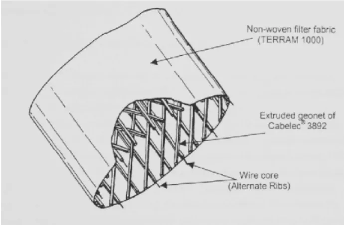
Figure 4: Electrically conductive band
drain
This patented design overcomes the problem of electrode corrosion. Therefore, no new electrodes can be replaced during electro kinetic testing in the field caused by degradation of electrodes under high acidity environment which affect the efficiency of the system and high cost of installation. By forming the electrode as a geosynthetic, EKG overcomes the problem of removing clean water by utilizing the drainage and filtration functions of geosynthetics. The ability of EKG to take on wide variety of shapes and forms means that they can be manufactured to suit a range of different application (Glendinning et al., 2007).
EKG has been utilized for slope remediation by amont-Black & Weltman (2010) as both active and passive roles. EKG drains actively attract water while EKG reinforcement not only provides reinforcement but also increases the shear strength of soils in which they are placed as well as improving soil bond. Therefore, EKG used for electro kinetic dewatering provides a potential alternative method in various applications that not only create select osmotic flow from the anode to the cathode but also provides reinforcement of weak soils and improving the shear strength of soil due to electrochemical effects (Pugh, 2002).This promising result of EKG electrode has led the used of this electrode in this study which was initiated by Liaki (2006).
Figure 5: Schematic of electro osmotic
consolidation
Volume I, Issue III, July - 2014
driving toward the cathode (Mitchell & Soga, 2005). Therefore, the electro osmotic consolidation depends on boundary condition at the anode and the cathode.
III. EXPERIMENTALAPPARATUSAND
MATERIALSREQUIRED
There has been much discussion in geotechnical literature on the variation of pH, water content and electrical conductivity on the physical properties of soft clays (i.e. shear strength, Atterberg limits and compressibility indices) but very little work to relate these factors to the physicochemical processes (i.e. cation exchange, precipitation, cementation and soil hardening) and electrochemical effects (i.e. electrolysis, electro osmosis and electro migration) within the soil matrix during and after treatment. Most of the researchers in geotechnical aspect have mentioned the possibility of these processes (ion exchange, precipitation and cementation) occurred during and after the electro kinetic treatment but very little explanation of the process occurring within the soil matrix under an influence of electric field due to the limitation knowledge related to electro kinetic phenomena and the scope of their studies which only concerning about the changes of physical properties However, in geo environmental aspect, the f undamental of electro kinetic process in the soil matrix is significant to them study to ensure the effectiveness of the system to remove the organic or inorganic contaminants in the soils. Drawn from the
Aspect of both studies, this research study has provided a useful knowledge of the main mechanisms and factors that contributing to the soil improvement. These main mechanisms and factors of EK processes can be evaluated and assessed to determine the performance and effectiveness of the system to improve soil properties (shear strength parameter, in this context of this study) for ground improvement. Therefore, the physical and chemical
Laboratory testing was chosen based on the ability of these tests to relate to such phenomena. For example, the Atterberg limit test was conducted to relate the changes in mineralogy after electro kinetic treatment and validated with other chemical test such as pH, electrical conductivity and chemical concentration of certain ions.
Batch Testing
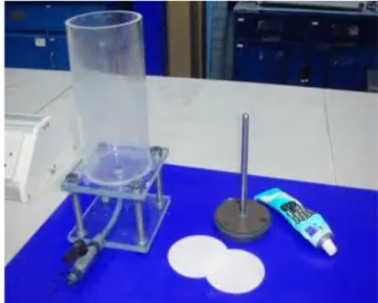
Batch testing was conducted in advanced before commencement of the main experimental programme in order to determine the effect of calcium chloride alone on shear strength of English China Clay using four different concentration (0.5, 1.0, 1.5, 1.5 and 2.0 mol/litre)for 3 days treatment durations. In addition, the batch testing was also conducted to check the efficiency of the electro kinetic setup using the Mariotte bottle method to maintain the water level when the chemical solution was continuously supplied at the anode electrode.
EK cylinder (50mm diameter and 90 mm long) was
equipped with an outlet port located at the middle of the bottom base to allow discharge of water during consolidation and EK testing. EKG electrodes used for anode and cathode and were cut in circular shape to fit in the EK cylinder and able to connect to the DC power supply. The loading plastic plate w as placed on the top of the sample to consolidate the sample until reach the required level. It has three holes to supply the electrolyte during EK testing and to connect a wire from electrode to the power supply. The dial gauge was attached at the top of loading hanger to measure the settlement of the soil during consolidation and EK testing the sample was loaded incrementally by using the loading plate and dead weights. All the sample preparation in this batch testing was similar to the main experimental programme. After consolidation, the inflow tube was connected from the bottom of Mariotte bottle to top of the plate to continuously supply the water during the EK testing. Then, the water discharge was collected at the graduated cylinder for monitoring purpose. After testing, the shear strength of the soil is measured using vane shear test in the small cylinder. The batch test results were utilized to assess the strength behaviour of English China Clay mixed with different concentrations of calcium chloride.
Based on the results, there was an increasing trend in the shear strength with0.5, 1.0, 1.5 and 2.0 mol/litre sodium silicate compared to the distilled water only (0mol/litre). However, highest shear strength was achieved at 22 kPa with 1.5 and 2.0mol/litre sodium silicate compared with distilled water of 8 kPa. Thus, this indicates that 1mol/litre sodium silicate used for main experimental programme at the anode chamber was effective dosage to give a reasonable strength.
Figure 6: Batch testing apparatus.
Sample Preparation
Volume I, Issue III, July - 2014
uniformity of the sample. Firstly, 10.66 kg of deionizer water was poured into the mixer bowl and then 11.84 kg of dry English China clay was gradually added to ensure consistency of mixing.
The slurry sample was then mixed using Hobart mechanical mixer and blended thoroughly for 30 minutes. The mechanical mixer was set at the lowest speed to prevent sample splashing out from the mixer bowl. It was necessary to stop the mixer and scrape unmixed portions around the sides and bottom of the bowl into the mixture and continue mixing to promote uniform blending. Two mixtures of slurry samples were placed in the tank and these mixtures were mixed a bit to prevent a layer forming. The total of amount of soil and water in the tank was 23.68 and 21.32 kg, respectively, achieving a water content of 51 %for all test samples. At this stage, two mixtures of slurry samples were poured into the main compartment that had been setup. A vibrator was used for every mixture placed into tank to remove air trapped inside the soils and to level the top of the soils slurry after finished pouring the second mixture. Then, the slurry sample was left overnight to ensure homogeneity. The initial height of the slurry is 386 mm for all tests
samples. The load was applied to consolidate the slurry sample until it reached final height of about 271 mm using hydraulic jack as shown in Figure 5.6 to achieve water content of51%. The final water content of 51 % was chosen due to practical reasons, such as the easy removal of the 3 mm thin solid plastic sheets with minimal disturbance of the soil and the insertion of the electrodes at each end of the main compartment of the tank and as suggested by Liaki (2006) which in the trial test, 45 % water content had caused soil Disturbance in such situation.
Monitoring of EKS Testing
During electro kinetic testing the variation of current, electric resistance, acolytes and catholyte solutions were monitored as this depends on time durations. The amount of effluent water from the Mariotte bottles and effluent water collected at graduated cylinders were also monitored over the same period of time. For the first day of the treatment, threading of current value was taken at 1, 2, 4, 6 and 8 hours to establish profile and data was subsequently taken every 24 hours for the remainder of the test duration, while the second Day and afterward data was taken every 24 hours. Samples of anolyte and catholyte solutions were taken every 24 hours together with water collected at graduated cylinders.50 ml of anolyte and catholyte solutions are extracted from the small compartments using syringe. The bottles of samples were labeled and then stored in a controlled temperature room at 4.0 0.5˚C for pH and conductivity measurement.
Tests for Physical Properties of Treated
Soil
1.ATTERBERG LIMIT
2.Moisture Content 3.Hand Vane Shear Test
4.Test For Chemical Properties Of Treated Soil
IV. EXPERIMENTALPROGRAMEAND
RESULTS
The electric current variations with treatment
time for the same type of electrode are comparable with Liaki (2006) who reported that the electric current initially increase at about 14 mA, while it then drops within the first 100 hours of treatment, as resistance of the materials increases and the voltage was set at the constant level. It has observed that a large variation of electric current distribution is reported especially at the beginning of the test with different treatment time (varied from14 to 22 mA) compared to the current research (varied from 9 to 14 mA). This was due to the soil electrode contact which varied and not consistent upon insertion of electrode during sample preparation prior to EKS test as observed by the author in Liaki (2006) study. Therefore, the improvement of the procedures and design configuration made for the current research has overcome the problem related to the soil-electrode interfaces during soil preparation. It should be note that after consolidation thin solid plastic walls were removed at both end of soil compartment and the gaps left were then inserted by the EKG electrodes. In order to make sure a good contact between soils and electrodes during sample preparation, the soil samples were subjected to load under the same loading of the last consolidation for about 24 hours before electric current we returned on.
In term of performance of the experiment and quality assurance, the monitoring data of electric current and volume of effluent can give indirect measurement of the efficiency of the system during EK treatment. This also gives indication of the cost of operation, i.e. an increase in electrical resistance results in higher energy expenditure. The electric current varied in time depending upon the changes in the electrical conductivity of the soil. According to Alshawabkeh & Sheahan (2003), the increase in electric current is due to the effect of electrolysis on the anolyte and catholyte to release ion hydrogens and hydroxides, respectively, and addition of chemical solution at the electrodes in the first 24 hours. However, after 24 hours, the electrical current trends seem to decrease with time due to the Precipitation, thus decreasing the ionic content and the electrical conductivity of the soil. In addition, the decrease in electric current is attributed to the soil-electrode interface resulting in voltage drop as reported by Rittirong et al. (2008). Similarly, Liaki (2006) has stated that the variation of current throughout the test is due to contact between soil and
Volume I, Issue III, July - 2014
V. CONCLUSION
The aim of this work was to evaluate the use of EKS as a method to strengthen soils. This was achieved through three objectives, namely:
(1) The development of new EKS treatments methods monitored through adapted experimental process draw from (Liaki, 2006)
(2) To assess the degree of strengthening that takes place when different stabilizers are added under a given voltage gradients.
(3) To investigate various electrochemical effects on physical, chemical and physicochemical behaviour of soft clay soil.
Importantly, the work present herein has allowed development of the EKS technique through the use of the base model developed by Liaki (2006), allowing both a better understanding of how the EKS process takes place and how monitoring can be conducted. This provides details essential for ultimate application of the EKS to field situations. In particular evaluation of different treatment solutions provide key information on what can be achieved and importantly what is needed to ensure successful enhancement of given properties can take place. The results of electrical conductivity of anolyte and catholyte depend on the type of electrolyte used and electrolysis process to produce hydrogen ions and hydroxide ions. These results also indicate the efficiency of the system to promote migration of Ca and Si ions in the CaCl-DW, DW-NaSiO and CaCl-NaSiO systems.
V. FUTURE WORK
Ultimately, the key aim of research effort into electro kinetic stabilization is to provide a viable and consistent stabilization method that can be used under existing foundations without adversely affecting the ground in ways that other improvement techniques can do.
REFERENCES
[1]
[1] Acar, Y.B. & Alshawabkeh, A.N. (1996) “Electrokinetic remediation. I: Pilot-scale tests
[2]
with lead-spiked kaolinite.” J. Geotech. Eng. 122, 173–185. [2] Casagrande, L. (1952) “Electro-osmotic stabilization of soils.” Journal
of Boston Society [3]
of Civil Engineers, Vol. 39, 51–83.
[3] Chappell, B.A. & Burton, P.L. (1975) “Electro osmosis applied to unstable embankment.”
[4]
J. Geotech.Eng. Div., ASCE 101(8), 733–740.
[4] Esrig, M.I. (1968) “Pore pressure, consolidation and electro kinetics.” Journal of Soil
[5]
Mechanics and Foundation Division, ASCE 94 (SM4), 899-922. [5] Fourie, A.B., Johns, D.G. & Jones, C.J.F.P. (2007). “Dewatering of
mine tailings using [6]
electrokinetic geosynthetics.” Canadian Geotechnical Journal, 44, 160-172.
[6] Glendinning, S., Lamont-Black, J., Jones C.J.F.P. (2007) “Treatment of sewage sludge
[7]
using electro kinetic geosynthetics.” J Hazard Mater 139:491–499 [7] Jayasekera, S. & Hall, S. (2006) “Modification of the properties of
salts affected soils [8]
using electrochemical treatments.” Journal of Geotechnical and Geology Eng.
[8] Lamont-Black, J. (2001) “E. K. G.: The next generation of geosynthetics.” Ground
[9]
Engineering, 34, 22-3.
[9] Morris, D.V., Hills, S.F. & Caldwell, J.A. (1985) “Improvement of Sensitive Silty Clay by
[10]
Electro osmosis,” Canadian Geotechnical Journal, Vol 22, 17-24. [10] Cort, T.; Bielefeldt, A. (2000). “Effects of Surfactants and Temperature
on PCP Biodegradation.” ASCE Journal of Environmental Engineering 126(7): 635-643.
[11] Gray, D.H.; Mitchell, J.K. (1967). “Fundamental Aspects of Electro-osmosis in Soils.”Journal of the Soil Mechanics and Foundations Division, Proceedings of the American Society of Civil Engineers 93(SM6): 209-236.
[12] Lageman, R.; Pool, W.; Seffinga, G. (1989). Electro reclamation - Theory and Practice. Chemistry and Industry 18th September 1989, pp.585-590.
[13] Lee, H-H.; Yang, J-W. (2000). “A new method to control electrolytes pH by circulation system in electro kinetic soil remediation.” Journal of Hazardous Materials B77: 227-240.
[14] Lo, K.Y.; Ho, K.S.; Inculet, I.I. (1991b). “Field Test of Electro osmotic Strengthening of Soft Sensitive Clay.” Canadian Geotechnical Journal 28: 74-83.
[15] Mayes, B.A.; Brown, G.L.; Montello, F.J.; Holtzclaw, K.W.; Hamilton, S.B.; Ramsey,A.A. (2002). “Dermal Absorption in Rhesus Monkeys of Polychlorinated Biphenyls from Soil Contaminated with Aroclor 1260.” Regulatory Toxicology and Pharmacology 35:289-295. [16] Miles, A.A.; Misra, S.S.K.; Irwin, J.O. (1938). “The estimation of the
bactericidal power of the blood.” Journal of Hygiene 38: 732-749. [17] Schinner, F.; Öhlinger, R.; Kandeler, E.; Margesin, R. (1993).
"BodenbiologischeArbeitsMethoden." Springer, Berlin, Germany (ISBN 3540562060).
[18] Sinclair, D.C.R.; Smith, G.M.; Bruce, A.; Staines, H.J. (1997). “Soil dehydrogenates activity adjacent to remedially treated timber, weathered in a physical field model.”International Bio deterioration and Biodegradation 39(2-3): 207-216.