Performance Improvement of IUPQC in Distribution System
under Abnormal Conditions Using PID
1N. Atchutha Madhuri 2K. Arun Kumar 3Ch. V. V. Manga Lakshmi 1
M. Tech. Student, 2Assistant.Professor, Dept Of EEE, KITS Divili
3Research Scholar
Abstract
: To improve the performance of feeders in the distribution system a new topology is introduced in this paper based on the interline unified power quality conditioner (IUPQC). This IUPQC consists of both series and shunt voltage source converters and these to are connected together to form a common bus which is placed in between the 2 different feeders to compensate the bus voltage in one feeder while controlling the voltage across the non-linear load in the other feeder. In the earlier stage the IUPQC is operated with VSC’S with PI controller to mitigatethe harmonics and sags, but in this paper by using of PID controller the faults in the feeders like sags and swells are reduced and efficiency of the feeder are also improved and it is observed and simulated using of MATLAB/ SIMULINK.
1. INTRODUCTION
The usage of number of electronic components in industries, residences etc, where these devices need high quality energy to work properly. VSC based CPD are highly used in custom-power applications to improve the power quality (PQ) in power distribution through the feeder [2]. It is used to regulate the voltage of distribution system [3], [4]. A DVR can used to replace the voltage sag/swell & distortion in source side voltage and the voltage across the load terminal is perfectly regulated[5], [6]. The Interline unified power-quality conditioner (IUPQC) is used by the use of both DSTATCOM and DVR [7], [8].The IUPQC consisting of two VSCs, which are connected to the dc bus.
The new methodolgy for an IUPQC with PID Controller to reduce the THD considerably to novel PID controller based voltage source converters. 2 feeders, F-1 and F-2, are connected to 2 different sub-stations, to send the supply to system loads L-1 and
L-2. The source voltages are shown by Vs1 and Vs2 [1]. It is taken that, the IUPQC is contacted to 2 buses B-1 and B-2, the terminal voltages of which are denoted by VT1 and VT2 respectively. The 2 If are shown by is1 and is2,. while the ILs are denoted by il1 and il2. The VL2is denoted by Vt2. The use of the IUPQC is to hold the voltages Vt1 and Vt2 constant against voltage sag, swell, faults & harmonics in either of the two feeders. It is shwoned that the IUPQC is absorbing power from Feeder-1 to Hold Vt2 constant in case of a sag in the voltage Vs2. The performance of IUPQC is evaluated by using of MATLAB/ SIMULINK.
2. STRUCTURE AND CONTROL
The IUPQC consists of two vsc’s.one is
shunt vsc, another is series vsc. The shunt vsc is called DSTATCOM, and series vsc is called DVR. Both are joined together by common energy storage dc capacitor. The DSTATCOM is connected to feeder-1 and the DVR is connected to feeder-2. the feeder impedances are denoted by the pairs (RS1, LS1) and (RS2, LS2).
International Journal of Science Engineering and Advance
Technology, IJSEAT, Vol. 3, Issue 12
ISSN 2321-6905
DECEMBER-2015
www.ijseat.com
Page 1336
It22 are current for these loades. The load L-2 is consider as sensitive load. It requires un interrupted and regulated voltage. The DSTATCOM is connected to feeder-1 and DVR is connected to feeder-2.
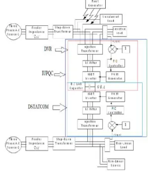
Figure 2.Complete structure of an IUPQC
The DSTATCOM is operated as voltage controller. In the structure of IUPQC the secondary side in parallel connected transformers is connected in star connection with neutral point to the load neutral point. The schematic structure of VSC is shown. The two VSC is realized by 3 H-Bridge inverters [10],[11].
Figure 3. Schematic structure of VSC
In this figure each switch represents a power semiconducting device like IGBT. And anti parallel diode. The single DC capacitor was given to supply to the all inverters. And each inverter was connected to transformer output. (A)IUPQC power system: block diagram& simulation diagram of the power circuit of IUPQC system are shown above figure.4&fig.5.consists of the 3-arm IGBT based inverter and the battery as energy storage system. The source is 11KV distribution system and step down to 415V at before connecting to load. In this paper the two types of loads are considered. One is non sensitive load, another is sensitive load. In this the
LC filter is placed for eliminate the switching ripples produced by the inverter.
A fault generator is introduced intentionally to generate voltage symmetrical& un symmetrical faults at different levels& by varying fault resistance value we can inject harmonics in to the system by diode rectifier. The sags & swells are given at 3-phs grid supply. In this circuit feeder-1 is taken in down side. Feeder-2 is taken at upper side
fig.4 block diagram of IUPQC power circuit
Fig.5 Simulation Diagram in MATLAB
Integral Derivative (PID) controller.
Proportional Integral Derivative (PID) Controller: The main aim of this controller is to maintain constant voltage magnitude at sensitive load during supply disturbances. This method is based on comparing source and load voltage. The 3-phs voltage is transformed to dqo, using park transmission. After converting the voltage is constant with d-voltage is 1 in p.u & q-voltage is 0 in p.u under the normal and balanced condition. But it varies under abnormal condition. After comparison d & q voltages with the desired voltage, the change in voltage is enhanced by PID controller, after it go through dqo to abc transformation to convert in to abc component which is the main signal to generate switching pulses of voltage source PWM inverter.
The main role of controller is to detect the voltage sag, swell, harmonics & faults, inject voltage variation and turn off inverter, when voltage sag event in the system is removed fig.6 represents the PID controller placed in feed back path. The input of the sensitive load voltage, VSL measured by 3-phs V-I measurement at sensitive load in p.u. VSL is transformed in dq term. The measuring error is detected the voltage sag by comparing dq voltage and reference values. Such error is processed by a PID controller. The d-reference is set to 1 and q-references is set to 0.
Fig.6 PID-Controller
ii) PWM voltage control in inverter: AC loads are requiring constant voltage at their input terminals. When inverter taken that loads, the output voltage of inverter is to controlled as to complete the requirement of ac loads. An AC load may require a constant input voltage through different levels. For such load, any deviations in the dc input voltage must be same as compensated in order to maintain constant
voltage at the load terminals at the desired level. There are 4 methods for external control of ac output voltage obtained from inverter output terminals. These methods are: a) AC voltage control
b) series-inverter control c) shunt-inverter control
d) Pulse width modulation control. In PWM control method, a fixed DC input voltage is given to the inverter and a controller AC output voltage is obtained by adjusting the on and off period of the inverter components.The PWM control method is most popular method for controlling output voltage.PWM inverters are mostly used over remaining types of inverters in industrial applications. These techniques are characterized by constant amplitude pulses. The width of these pulses are modulated to obtain inverter output voltage control and to reduce its harmonic content.
The different PWM techniques are a) single-pulse modulation b) multiple-pulse modulation c) sinusoidal-pulse modulation.
In PWM inverter forced commutation is essential. The 3 PWM techniques are different from each other in harmonic content in their output voltage. PWM Inverters are gradually taking over other types of inverters in industrial applications. PWM techniques are characterized by constant amplitude pulses. The width of these pulses is however, modulated to obtain inverter output voltage control and to reduce its harmonic content. Different types of swithing techniques are as under
a) Single–puse modulation b) Multiple–pulse modulation c) Sinusoidal pulse modulation
In PWM inverters, forced commutation is essential. The above switching techniques shows difference in between them like THD and in Vo. The converter Vo can be decreased using various control techniques. The switching techniques can be designed for the lowest harmonic content. It should be mentioned that these techniques require more no. of switching per cycle leading to higher converter losses. Therefore, switching techniques are currently considered unpractical for large voltage applications. However, it is expected that recent Integral Derivative (PID) controller.
Proportional Integral Derivative (PID) Controller: The main aim of this controller is to maintain constant voltage magnitude at sensitive load during supply disturbances. This method is based on comparing source and load voltage. The 3-phs voltage is transformed to dqo, using park transmission. After converting the voltage is constant with d-voltage is 1 in p.u & q-voltage is 0 in p.u under the normal and balanced condition. But it varies under abnormal condition. After comparison d & q voltages with the desired voltage, the change in voltage is enhanced by PID controller, after it go through dqo to abc transformation to convert in to abc component which is the main signal to generate switching pulses of voltage source PWM inverter.
The main role of controller is to detect the voltage sag, swell, harmonics & faults, inject voltage variation and turn off inverter, when voltage sag event in the system is removed fig.6 represents the PID controller placed in feed back path. The input of the sensitive load voltage, VSL measured by 3-phs V-I measurement at sensitive load in p.u. VSL is transformed in dq term. The measuring error is detected the voltage sag by comparing dq voltage and reference values. Such error is processed by a PID controller. The d-reference is set to 1 and q-references is set to 0.
Fig.6 PID-Controller
ii) PWM voltage control in inverter: AC loads are requiring constant voltage at their input terminals. When inverter taken that loads, the output voltage of inverter is to controlled as to complete the requirement of ac loads. An AC load may require a constant input voltage through different levels. For such load, any deviations in the dc input voltage must be same as compensated in order to maintain constant
voltage at the load terminals at the desired level. There are 4 methods for external control of ac output voltage obtained from inverter output terminals. These methods are: a) AC voltage control
b) series-inverter control c) shunt-inverter control
d) Pulse width modulation control. In PWM control method, a fixed DC input voltage is given to the inverter and a controller AC output voltage is obtained by adjusting the on and off period of the inverter components.The PWM control method is most popular method for controlling output voltage.PWM inverters are mostly used over remaining types of inverters in industrial applications. These techniques are characterized by constant amplitude pulses. The width of these pulses are modulated to obtain inverter output voltage control and to reduce its harmonic content.
The different PWM techniques are a) single-pulse modulation b) multiple-pulse modulation c) sinusoidal-pulse modulation.
In PWM inverter forced commutation is essential. The 3 PWM techniques are different from each other in harmonic content in their output voltage. PWM Inverters are gradually taking over other types of inverters in industrial applications. PWM techniques are characterized by constant amplitude pulses. The width of these pulses is however, modulated to obtain inverter output voltage control and to reduce its harmonic content. Different types of swithing techniques are as under
a) Single–puse modulation b) Multiple–pulse modulation c) Sinusoidal pulse modulation
International Journal of Science Engineering and Advance
Technology, IJSEAT, Vol. 3, Issue 12
ISSN 2321-6905
DECEMBER-2015
www.ijseat.com
Page 1338
developments on power electronic switches will allow practical use of PWM controls on such applications in the near future. As per their simplicity many authors, i.e. have used PWM control techniques in their IUPFC studies.
When SPWM switching technique is applied to turn on and turn off signals for GTOs are generated comparing a sinusoidal reference signal Vr of amplitude Ar with a saw wave carrier waveform Vcof amplitude Ac. The frequency of the saw waveform establishes the frequency at which GTOs are switched..The 50HZ freq of the converter Vo is determined by the frequency of the base signal. Controlling the amplitude of the reference signal controls the distance between the pulses. The magnitude modulation index is defined as separation of Arto Ac.
m = Ar/Ac.
For m≤1the peak magnitude of the 50HZ freq of the converter
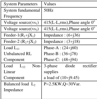
Vo can be expressed as V=m Vdc/2. Table 1. System Parameters
3. SYSTEM DESCRIPTION
An IUPQC connected to a distribution system is shown in Fig.1. In this figure, the feeder impedances are denoted by the pairs (R1,X1) and (R2,X2). It can be seen that the two feeders supply the loads 1 and L-2. The load L-1 is assumed to have two separate components—an unbalanced part (L-11) and a non-linear part (L-12). The currents drawn by these two loads are denoted by iL11and iL12 , respectively. We further assume that the load L-2 is a sensitive load that requires un-interrupted and regulated voltage. The series VSC (VSC-1) is connected to bus B-1 at the end of Feeder-1, while the shunt VSC (VSC-2) is connected at bus B-2 at the end of Feeder-2. The voltages of buses B-1 and B-2 and across the sensitive load terminal are denoted by Vt1, Vt2, and Vt3, respectively. The aim of the IUPQC is two-fold to protect the sensitive load L-2 from the disturbances occurring in the system by regulating the voltage; to regulate the bus B-1 voltage against sag/swell and or disturbances in the system. In order to attain these aims, the shunt VSC-2 is operated as a voltage controller while the series VSC-1 regulates
the voltage V across the sensitive load. The system parameters used in the study are given in Table 1. The length of Feeder-1 is arbitrarily chosen to be twice that of Feeder.
4. IUPQC OPERATION
As we know that VSC-2 like DSTATCOM injects current into the feeder-2 whereas VSC-1like DVR regulates voltage in the feeder-1.Both gets supply from opposite feeder when they are operating for their corresponding feeders through a D.C link capacitor. PID Controller is used to generate the control signals to PWM pulse generator which in turn helps to control the inverter operation. IUPQC is an interline UPQC connected between two 11KV/415 distribution feeders which can alone controls the feeder operation under abnormal conditions like Sag, Swell, Harmonics, Symmetrical & Asymmetrical faults. D.C link acts as a source to individual feeder
connected VSC’s. Unbalanced resistive/ impedance
load can be connected to feeder-1 along with a non-linear load, sensitive uncontrolled non-linear load is connected to feeder-2.
5. SIMULATION RESULTS
System Parameters Values
System fundamental 50Hz Frequency
Voltage source(vs1) 415(L-L,rms),Phase angle 0o Voltage source(vs2) 415(L-L,rms),Phase angle 0o
Feeder-1(R1+jX1) Impedance : (6+j36)Ω Feeder-2 (R2+jX2) Impedance : (3+j18) Ω Load L11 Phase-A : (24+j60) Ω Unbalanced RL Phase-B : (36+j78) Ω
Component Phase-C: (48+j94) Ω
Load L12 Non-Linear
3-phase diode rectifier supplies
Component a load of (10+j9.45) Ω
The IUPQC consists of two-voltage source converters that are connected to back-to-back through common energy storage DC capacitor. One Voltage Source Converter (VSC-2) is connected in series with the feeder-2 i.e., DVR and another voltage source converter is connected in shunt with the feeder-1 i.e., DSTATCOM. Two separate load components are connected in feeder-1 i.e. unbalanced and nonlinear loads. The sensitive load is connected in feeder-2. Here simulation results have taken under individual abnormal conditions & in combined cases with PID controller acting one at a time in the IUPQC system.THD in the system is observed to system with PID controller. In [13], Sags and Harmonics are mitigated with IUPQC connection using conventional PID controller.
In [14], under abnormal conditions performance of DVR connected to a single feeder system is investigated with PID controller. Here, with IUPQC system operated with PID is investigated first for abnormal and dangerous conditions like sags, swells, harmonics, symmetrical and asymmetrical faults. Using MATLAB/Simulink software the IUPQC connected between two feeders is investigated with a fault generator block for LLG and LLLG.
By using an uncontrolled diode bridge, harmonics are created and injected into the system. By adjusting the amplitude values less than 1.0 p.u sag is created between time periods like 0.14 to 0.24s, and by adjusting the amplitude values greater than 1.0 p.u, swell is generated between the time periods like 0.24 to 0.34 s in the three phase source block. All the blocks are taken from Simulink library. Here PID controller mitigated all the above abnormal conditions successfully.
The following are the different cases where simuX,lation results have taken in two ways with base voltage (VL=415v) which is converted to per unit values. Here peak value 325V (230V r.m.s) is taken as 1.0 p.u.
A) Individual Occurrences with PID
Case i: Mitigation of harmonics in feeder-1 in the total three phases system due to uncontrollable-diode
rectifier with load (10+j9.45) Ω during (0-0.5s).
Case ii: Mitigation of Sags in phase-B of feeder-2 during (0.14-0.24-0.30s).
Case iii: Mitigation of Swells in phase-B of feeder-2
during (0.14-0.24-0.30s).
International Journal of Science Engineering and Advance
Technology, IJSEAT, Vol. 3, Issue 12
ISSN 2321-6905
DECEMBER-2015
www.ijseat.com
Page 1340
Case v: Mitigation of Unsymmetrical (LLG) fault i.e., two phases to ground in feeder1 during (0.10 -0.21s).
Case vi: Mitigation of Unsymmetrical (LG) fault i.e., two phases to ground in feeder1 during (0.10 -0.21s).
Total Harmonic Distortion at load voltage with PID controller
5.3.1With PID Controller
5. 6. 7. 8. 9. 10. 11. 12.
13. 6. Conclusion 14.
The paper illustrates the operation and control of an interline unified power quality conditioner (IUPQC).The device is connected between two feeders coming from different substations. An unbalanced and nonlinear load L-1 is supplied by Feeder-1while a sensitive load L-2 is supplied through Feeder-2. The main aim of the IUPQC is to regulate the voltage at the terminals of Feeder-1 and to protect the sensitive load from disturbances occurring upstream. The performance of the IUPQC has been evaluated under various disturbance conditions such as voltage sag, swell, harmonics & faults in either feeder. It has been shown that in case of voltage sag, the phase angle of the bus voltage in which the shunt VSC is connected plays an important role as it gives the measure of the real power required by the load. The IUPQC can mitigate voltage sag of about 0.1 p.u (415V) in both feeders for short duration. The IUPQC discussed in the paper is capable of handling System in which the loads are unbalanced and distorted. Here PID controller is used to control the PWM pulses given to controller.THD in FFT analysis of PID controller system with 1.71%.the controller mitigated the abnormal conditions like harmonics, symmetrical & asymmetrical faults, sags & swells in the distributed system along with D.C link connection successfully. Extensive case studies have been included to show that an IUPQC might be used as a FLC device for improving the power quality in an interconnected distribution system.
7. REFERENCES
[1] Raunak jangid, Kapil Parkh &Pradeep Anjana “
Reducing the Voltage Sag and Swell Problem in Distribution System Using Dynamic Voltage
Restorer with PI Controller” Published in IJSCE
ISSN: 2231-2307, Volume-3, Issue-6, January 2014. [2] Amit Kumar Jindal, Student Member, IEEE, Arindam Ghosh, Fellow, IEEE, and Avinash Joshi,
“Interline Unified Power Quality Conditioner”, IEEE
Transactions on power Delivery, vol.22, No.1, January 2007.
[3] Haque, M.H., “Compensation of distribution
system voltage sag by DVR and D- STATCOM”,
Power Tech Proceedings, 2001 IEEE Porto, vol.1, pp.10-13, Sept. 2001.
[4] Lim Yun Seng”, Algorithm for Designing the Size of Energy storage in Dynamic Voltage Restorer”
First International Conference on Industrial and Information Systems, ICIIS 2006, 8 - 11 August 2006.
[5] H. Masdi, N. Mariun, S. Mahmud, A. Mohamed and S. Yusuf, "Design of a prototype DSTATCOM for voltage sag mitigation", National Power and Energy Conference, pp. 61-66, November, 2004.
[6] Haddad.K, Josh.G,”Control Algorithm for Series
static Voltage Regulators in Faulted Distribution
System”, power electronics specialists’ conference,
Annual IEEE, vol.1,pp 418-423, Aug 1999.
[7] Kevork Haddad, GezaJoos, “A Fast Algorithm for
Voltage Unbalance Compensation and Regulation in Faulted Distribution Systems”, Proceedings of IEEE Applied Power Electronics Conference (APEC’98),
vol.2,pp. 963-969, February 1998, New York, USA.
[8] K. Haddad and G. Joos, “Distribution System
Voltage Regulation under Fault Conditions Using
Static Series Regulators”, in* IEEE
Industrial.Appl.IAS‘97 Conference Rec.vol.2,
pp.1383-1389, Oct. 1997, New Orleans.
[9] P. A.Venkatachalam*, K.Chandrasekaran, Mohd
Noh Karsitis “Simulation and Analysis of Power Quality Disturbances on a Distribution System”
Proceedings of the International Conference on Electrical Engineering and Informatics Institute Technology Bandung, Indonesia June 17-19, 2007. [10] HendriMasdi,NormanMariun, S.M. Bashi
“Construction of a Prototype D-Statcoms for Voltage
Sag Mitigation”, European Journal of Scientific Research ISSN 1450-216X, vol.30, No.1 (2009), pp.112-127, Euro Journals Publishing, Inc. 2009. 52 [11] H. Ezoji A, Sheikholeslami M, Tabasi ,M.M.
Saeednia “Simulation of Dynamic Voltage Restorer Using Hysteresis Voltage Control”, European Journal
of Scientific Research ISSN 1450-216X vol.27 No.1 (2009), pp.152-166© Euro Journals Publishing, Inc. 2009.
[12] Dale R Patrick, Stepwen W. Fardo”Electrical Distribution Systems”, edition no-2 publisher Liiburn,GA:Fairmont press,2008.
[13] A. Ghosh and G. Ledwich,” Power Quality Enhancement Using Custom Power Devices”, Norwell, MA: Kluwer, 2002.
AUTHORS PROFILE
N.ATCHUTHA MADURI was born in Kakinada, Andhra Pradesh ,India in 1989. she obtained the B.Tech Degree in Electrical & Electronics Engineering from V.S.LAKSHMI engineering College matlapalem near Kakinada, A.P in 2012.She is pursuing M.Tech in Power Electronics from kits Engineering College, divili, A.P, India.
K.ARUN KUMAR, he obtained M.Tech degree in Power electronics from KlTS engineering College, Divili and he is presently working as assistant Professor in EEE Department at KITS, engineering College, Divili. His research interest on DVR and DSTATCOM.