Integrated with Boost-Buck-Boost Topology on Solar & Wind Renewable
Energy Resources
1Garaga S S Ramesh,2T Amar Kiran
1M.Tech(Research scholar),2Associate Proffesor in Dept. of EEE
Godavari Institute of Engg. & Technology Rajahmundry,A.P,INDIA
Abstract: The integration was started with wind farms. When
the price for photovoltaic panels became affordable, the penetration of PV became to be used more often but not necessarily at the same level of power as wind. For medium to
high power the PV’s are modularly used. Many studies propose
small power integration (few kW) for both wind and solar PV as hybrid stand-alone systems. Other studies added fuel cells and batteries creating the concept of multi-port system. I have proposed a double-port boost-buck-boost (BBB) topology that enhances the power capability of the PV-Wind power system during partial solar irradiation and weak winds. In this paper a hybrid power electronics interface that combines the energy from solar photovoltaic panel and wind generator into a small scale stand-alone system is proposed. After the description of operation of this Dual-port interface, a simulation model for 1 kW PV array integrated together with a 1.5 kW wind generator was developed and simulation results are presented.
I. Introduction
In general, demand in classic energy resources made expensive affair like oil and coal. So there is a need to solute with clean renewable energy sources among other solar and wind. The progress in power electronics facilitated integration of these renewable energy sources either grid or as stand-alone for small scale use. Historically, the integration was started with wind farms. When the price for photovoltaic panels became affordable, the penetration of PV became to be used more often but not necessarily at the same level of power as wind. For
medium to high power the PV’s are modularly used. Many
studies propose small power integration (few kW) for both wind and solar PV as hybrid stand-alone systems. Other studies added fuel cells and batteries creating the concept of multi-port system. Apart from methods of integration a continuous attention was towards controlling the systems in order to maximize solar PV efficiency or wind.
Stability of renewable system was also under scrutiny. Double or multi-port integration systems for renewable have been previously proposed. The communality of all these studies proposed parallel connection of various renewable sources on a single dc bus. In this study a double-port integration system for renewable energy sources is proposed. Figure 1 shows a small scale system of 1 kW PV array integrated together with a 1.5 kW wind generator (WG).
II. Small Scale Renewable System
When an operating at nominal conditions, the dual input interface converts energy delivered by the PV array and wind generator in a comparable DC voltage. Due to the variable nature of wind and sun irradiation, the system must have a battery backup. In this proposed solution the corresponding DC output voltage for each renewable source is connected in series and thus increasing the power availability at partial solar irradiation and weak wind.
Fig.1 Double Input Renewable System
The third stage of the interface produces a charging current for the battery. During the day light, the consumption is lower than the PV can produce and the greatest part of this energy is stored into the battery. When the wind blows, the energy produced by the wind generator is also stored into battery. Energy stored is then released for the period when there is no sun or wind. The output of the system is a single-phase standard voltage 50 Hz PWM inverter capable of delivering 3 kW at peak demand.
Photovoltaic system:
be either stored, used directly (island/standalone plant), or fed into a large electricity grid powered by central generation plants (grid-connected/grid-tied plant), or combined with one or many domestic electricity generators to feed into a small grid (hybrid plant). Systems are generally designed in order to ensure the highest energy yield for a given investment.
Background
Today, solar-generated electricity serves people living in the most isolated spots on earth as well as in the centre of our biggest cities. First used in the space program, photovoltaic (PV) systems are now both generating electricity to pump water, light up the night, activate switches, charge batteries, supply the electric utility grid, and more. Whether you are a homeowner, farmer, planner, architect, or just someone who pays electric utility bills, PV may already touch your life in some way.
We group PV applications into the following categories:
• Simple or "Stand Alone" PV Systems • PV with Battery Storage
• PV with Backup Generator Power • PV Connected to the Local Utility • Utility-Scale Power Production
• Hybrid Power Systems
Simple PV Systems
The same sunny days that dry out plants, make animals thirsty, and heat up buildings and cars are also good days for
generating electricity with photovoltaic’s. This electricity can be
used to power water pumps for irrigation and drinking wells, and ventilation fans for air cooling. For this reason, the most simple PV systems use the dc electricity as soon as it is generated to run water pumps or fans.
These basic PV systems have several advantages for the special jobs they do. The energy is produced where and when it is needed, so complex wiring, storage, and control systems are unnecessary. Small systems, under 500 watts (W), weigh less than 68 kilograms (150 pounds), making them easy to transport and install. Most installations take only a few hours. And, although pumps and fans require regular maintenance, the PV modules require only an occasional inspection and cleaning.
PV with Battery Storage
Storing electrical energy makes PV systems a reliable source of electric power day and night, rain or shine. PV systems with battery storage are being used all over the world to power lights, sensors, recording equipment, switches, appliances, telephones, televisions, and even power tools.
PV systems with batteries can be designed to power dc or ac equipment. People who want to run conventional ac equipment add a power conditioning device called an "inverter" between the batteries and the load. Although a small amount of energy is lost in converting dc to ac, an inverter makes PV-generated electricity behave like utility power to operate everyday ac appliances, lights, and even computers.
A. Photovoltaic cell model for proposed system
The equivalent model of a photovoltaic cell is shown in figure 2. The current-voltage characteristic of the cell is:
Where:
I = output current; Iph = photo current;
Io =saturation current of the diode; V = output voltage;
q = the charge of electron;
n =∈[1 2] is the diode constant;
K = Boltzmann constant;
T= cell’s temperature in Kelvin degrees;
Rs = series resistance; Rsh = shunt resistance.
In this study, four panels rated at approximate 250 W with Voc of 37 V and Isc–8.9 A. Figure 3 and 4 shows the I-V and power characteristic of one panel at standard conditions rerspectively. For an efficient energy conversion, the panel should be operated in the MPP point.
Fig.2 PV Cell’s equivalent model
Fig.3 I/V characteristics
B. Wind generation model
The mechanic power produced by the wind blowing the blades is given as:
Whereρ is the air density (kg/m3), A is the turbine swept area (m2) and vW is the wind speed (m/s). Coefficient Cp is a
dimensionless power coefficient which depends on λ and the
blade pitch angle (β) [13]:
With:
Whereωmis the angular speed of the turbine and R is the radius of the turbine/blades. Then, the electromagnetic torque (Tem) of the generator can be written as:
Where J is total inertia, B is the effective friction coefficient, p is
the number of poles, Ψ is the flux linkage,E is the amplitude of
the emf and I is the amplitude of the generator output current. Then the wind turbine maximum power for different wind speeds (see figure 5) is going to be matched by electric load connected to the generator.
Fig. 5 Turbine output power and speed
Hydroelectricity:
The energy from moving water is converted to electricity when water passes by blades similar to those on a
ship’s propeller. The blades are connected to a rotating shaft
which turns a generator to produce electricity. Hydroelectric power plants in Wisconsin range from large, utility-owned dams on major rivers to small locally-owned dams on small streams.
III. Power Electronic For Wind Power Generation Systems A. Characteristics of Wind Power Conversion
The aerodynamic power, , of a wind turbine is given by
where R is the air density, is the turbine radius, is the wind speed, and Cpis the turbine power coefficient which represents the power conversion efficiency of a wind turbine. Cp is a
function of the tip speed ratio , λ as well as the blade pitch angle β in a pitch controlled wind turbine. λ is defined as the ratio of
the tip speed of the turbine blades to wind speed, and given by
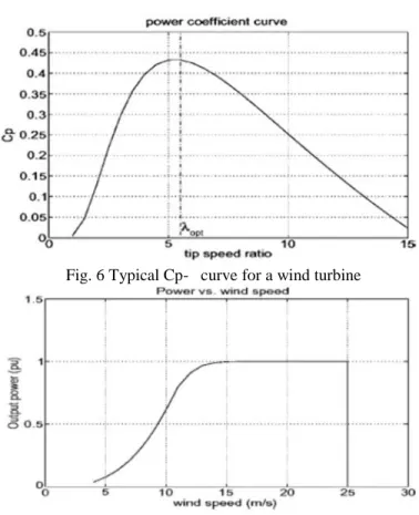
where is the rotational speed of the wind turbine. A typical curve for a fixed pitch angle is shown in Fig. 1. It can be seen that there is a maximum power coefficient,
.
Fig. 6 Typical Cp-λ curve for a wind turbine
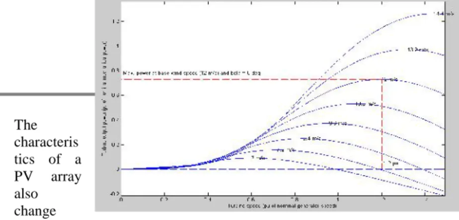
Fig. 7 Power–wind speed characteristics for a wind turbine Normally, a variable speed wind turbine follows the
typical power- wind speed curve with a cut-off wind speed of 25 m/s is shown in Fig. 2, however, the cut-off wind speed may vary depending on the type of wind turbines.
B. Variable Speed Wind Turbines
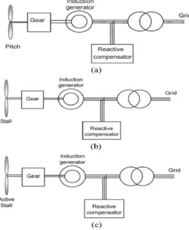
The development in wind turbine systems has been steady for the last 25 years and four to five generations of wind turbines exist [1]. The wind turbine technology can basically be divided into three categories: the systems without power electronics, the systems with partially rated power electronics and the systems with full-scale power electronic interfacing wind turbines. The wind turbine systems in Fig. 3 using induction generators, which independent of torque variation, keep an almost fixed speed (variation of 1–2%). The power is limited aerodynamically either by stall, active stall or by pitch control. A soft-starter is normally used in order to reduce the inrush current during start-up. Also a reactive power compensator is needed to reduce (almost eliminate) the reactive power demand from the turbine generators. It is usually done by activating continuously the capacitor banks following load variation (5–25 steps). Those solutions are attractive due to low cost and high reliability.
Fig. 8 Wind turbine systems without power converter but with aerodynamic power control: (a) pitch controlled, (b) stall controlled, and (c) active stall controlled.
The next category is wind turbines with partially rated power converters and much more improved control performance can be obtained. Fig. 4 shows two such solutions. Fig. 4(a)
shows a wind turbine system where the generator is an induction generator with a wounded rotor. An extra resistance controlled by power electronics is added in the rotor, which gives a speed range of 2 to 4%. The power converter for the rotor resistance control is for low voltage but high currents. At the same time an extra control freedom is obtained at higher wind speeds in order to keep the output power fixed. This solution also needs a softstarter and a reactive power compensator.
Another solution of using a medium scale power converter with a wounded rotor induction generator is shown in Fig. 4(b). A power converter connected to the rotor through slip rings controls the rotor currents. If the generator is running super-synchronously, the electrical power is delivered through both the rotor and the stator. If the generator is running sub-synchronously the electrical power is only delivered into the rotor from the grid. A speed variation of 60% around synchronous speed may be obtained by the use of a power converter of 30% of nominal power. Furthermore, the required rating of the power converter can be higher, depending on the designed fault handing capability as well as the ability of controlling reactive power,
Fig. 9. Wind turbine topologies with partially rated power electronics: (a) rotor-resistance converter and (b) doubly fed induction generator.
which give a better grid performance. The solution is naturally a little bit more expensive compared to the classical solutions, however it is possible to save on the safety margin of gear, having reactive power compensation/production and more energy captured from the wind.
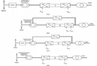
The third category is wind turbines with a full-scale power converter between the generator and grid, which gives extra losses in the power conversion but it will gain the added technical performance. Fig. 5 shows four possible solutions with full-scale power converters.
field excitation. Multipole generator systems with the synchronous generator without a gear are shown in Fig. 5(c) and (d). Permanent magnets are used for the system shown in Fig. 5(d), which are still becoming cheaper. Various power electronic interfaces may be used with permanent magnet wind power generators [6]–[8]. Simulation tools are developed to investigate the design and operation of the wind turbines [9]. All four solutions have the same controllable characteristics since the generator is decoupled from the grid by a voltage-sourced dc-link. The power converter to the grid enables a fast control of active and reactive power. However, the negative side is a more complex system with a more sensitive power electronic part. Comparing the different wind turbine systems in respect to performance shows a contradiction between the cost and the performance. By introducing power electronics many of the wind turbine systems behave like a power plant [10]. In respect to control performance they are faster, but the produced real power depends on the available wind. On the other hand they may always be able to deliver reactive power, which can be used for power system control.
Fig. 10 Wind turbine systems with full-scale power converters with active and reactive power control: (a) induction generator with gear, (b) synchronous generator with gear, (c) multipole synchronous generator, and (d) multipole permanent magnet synchronous generator.
Power electronic interface, the real power cannot easily be controlled without a pitch control mechanism or dumping devices. However, if the rotor is connected to the grid via power electronic converters as shown in Fig. 4(b), the offshore wind farm equipped with doubly fed induction generators can perform both real and reactive power control while operate the wind turbines in variable speed to maximize the energy capture and to reduce the mechanical stress and noise. The power electronic converters are normally only rated as a small part of the system capacity, say 20–30%. Since the controllability is related to the rating of the power electronic converters, other compensation methods/devices may still be required dependent on system demands. For long distance transmission of power from offshore
wind farm, HVDC may be a viable option. In a HVDC transmission, the low or medium ac voltage at the wind farm is converted into a high dc voltage on the transmission side and the dc power is transferred to the on-shore system where the dc voltage is converted back into ac voltage. For certain power level, a voltage source converter (VSC) based HVDC transmission system may be used instead of the conventional thyristor based HVDC technology. A configuration of using dc local network, decentralized control with a dc transmission, where each wind turbine has its own power electronic converter, so that it is possible to operate each wind turbine at an individual optimal speed. Each system configuration has its own feature and suitability; the most suitable system configuration for a particular wind farm has to be determined by taking the details of the concerned wind farm into consideration.
IV Control Strategy
The main purpose of the proposed system is to harvest energy from renewable sources in an efficient way. Hence the control strategy is towards each input converter to match the maximum power point for the corresponding source.
A. PV Input Control
For this application a simple PI regulator (figure 7) has been used for controlling the input current Ipv = IL1. The initial
set point (δ1) for switch S1 and value for L1 are chosen to
satisfy the maximum power point corresponding with standard solar irradiation of 1000 W/m2. One other parameter considered is panel temperature (Tpv); because the performances of photovoltaic cells depend on temperature.
Fig. 11 Control for solar PV MPPT
Maximum power point tracking:
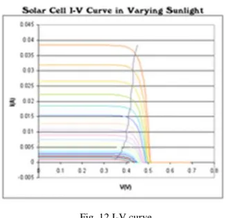
Fig. 12 I-V curve
Solar cell I-V curves where a line intersects the knee of the curves where the maximum power point is located.
Photovoltaic cells have a complex relationship between their operating environment and the maximum power they can produce. The fill factor, abbreviated FF, is a parameter which characterizes the non-linear electrical behavior of the solar cell. Fill factor is defined as the ratio of the maximum power from the solar cell to the product of Open Circuit Voltage Vocand
Short-Circuit Current Isc. In tabulated data it is often used to estimate
the maximum power that a cell can provide with an optimal load under given conditions, P=FF*Voc*Isc. For most purposes, FF,
Voc, and Iscare enough information to give a useful approximate
model of the electrical behavior of a photovoltaic cell under typical conditions.
For any given set of operational conditions, cells have a single operating point where the values of the current (I) and Voltage (V) of the cell result in a maximum power output. These values correspond to a particular load resistance, which is equal to V / I as specified by Ohm's Law. The power P is given by
P=V*I. A photovoltaic cell, for the majority of its useful curve,
acts as a constant current source.[4] However, at a photovoltaic cell's MPP region, its curve has an approximately inverse exponential relationship between current and voltage. From basic circuit theory, the power delivered from or to a device is optimized where the derivative (graphically, the slope) dI/dV of the I-V curve is equal and opposite the I/V ratio (where dP/dV=0).[5] This is known as the maximum power point (MPP) and corresponds to the "knee" of the curve.
A load with resistance R=V/I equal to the reciprocal of this value draws the maximum power from the device. This is sometimes called the characteristic resistance of the cell. This is a dynamic quantity which changes depending on the level of illumination, as well as other factors such as temperature and the age of the cell. If the resistance is lower or higher than this value, the power drawn will be less than the maximum available, and thus the cell will not be used as efficiently as it could be.
Maximum power point trackers utilize different types of control circuit or logic to search for this point and thus to allow the converter circuit to extract the maximum power available from a cell.
A typical solar panel converts only 30 to 40 percent of the incident solar irradiation intoelectrical energy. Maximum power point tracking technique is used to improve the efficiency of the solar panel. According to Maximum Power Transfer theorem, the power output of a circuit is maximumwhen the source impedance matches with the loadimpedance. In the source side a boost converter is connected to a solar panel in order to enhance the output voltage. By changing the duty cycle of the boost converter appropriately the source impedance is matched with that of the load impedance.Several approaches have been proposed for tracking the MPP [4]. Among those methods, the perturb and observe (P&O) and incremental conductance (INC) methods are widely usedalthough they have some problems such as the oscillation around MPP and confusion by rapidly changing atmospheric conditions [6,7]. In general, these tracking approaches use a fixed iteration step size, which is determined by the accuracy and tracking speed requirement.
MPPT placement:
Traditional solar inverters perform MPPT for an entire array as a whole. In such systems the same current, dictated by the inverter, flows through all panels in the string. Because different panels have different IV curves and different MPPs (due to manufacturing tolerance, partial shading,[16] etc.) this architecture means some panels will be performing below their MPP, resulting in the loss of energy.[1]
Some companies (see power optimizer) are now placing peak power point converters into individual panels, allowing each to operate at peak efficiency despite uneven shading, soiling or electrical mismatch.
Operation with batteries:
At night, an off-grid PV power system may use batteries to supply loads. Although the fully charged battery pack voltage may be close to the PV panel's maximum power point voltage, this is unlikely to be true at sunrise when the battery has been partially discharged. Charging may begin at a voltage considerably below the PV panel maximum power point voltage, and an MPPT can resolve this mismatch.
When the batteries in an off-grid system are fully charged and PV production exceeds local loads, an MPPT can no longer operate the panel at its maximum power point as the excess power has no load to absorb it. The MPPT must then shift the PV panel operating point away from the peak power point until production exactly matches demand. (An alternative approach commonly used in spacecraft is to divert surplus PV power into a resistive load, allowing the panel to operate continuously at its peak power point.)
Fractional Open-Circuit Voltage:
The near linear relationship between Vmpp and open circuit voltage of a PV array, under varying irradiance and temperature levels, has given rise to the fractional Voc method; the relationship between the Vmpp and Voc is almost linear.
Vmpp≈K1*Voc
Where k1 is proportionality constant, since k1 is dependent on the characteristics of the PV array being used, it usually has to be computed beforehand by empirically determining Vmpp and Voc for the specific PV array at different irradiance and temperature levels. The factor k1 has been reported to be between 0.71 and 0.78.
Once k1 is known, Vmpp can be computed with Voc measured periodically by momentarily shutting down the power converter. However, this incurs some disadvantages, including temporary loss of power. To prevent this, it can use pilot cells from which Voc can be obtained. These pilot cells must be carefully chosen to closely represent the characteristics of the PV array. Once Vmpp has been approximated, a closed-loop control on the array power converter can be used to reach this desired voltage. Since the relation is only an approximation, the PV array technically never operates at the MPP.
Fractional short-Circuit Current
Fractional short circuit current results from the fact that, under varying atmospheric conditions, Impp is approximately linearly related to the Isc of a PV array thus
Impp≈K2*Isc
Where K2 is proportionality constant, just like in the fractional Voc technique, K2 has to be determined according to the PV array in use. The constant K2 is generally found to be between 0.78 and 0.92. Measuring Isc during operation is problematic. An additional switch usually has to be added to the power converter to periodically short the PV array so that Isc can be measured using a current sensor. This increases the number of components and cost. It is clear that this method and the previous one have major drawbacks, the power output is not only reduced when finding Isc but also because the MPP is never perfectly matched.
Fuzzy Logic Control
Fuzzy logic controllers have the advantages of working with imprecise inputs, not needing an accurate mathematical model, and handling nonlinearity. Fuzzy logic control generally consists of three stages: fuzzification, rule base lookup table, and defuzzification. During fuzzification, numerical input variables are converted into linguistic variables based on a membership function. In this case, five fuzzy levels are used: NB (negative big), NS (negative small), ZE (zero), PS (positive small), and PB (positive big).
The inputs to a MPPT fuzzy logic controller are usually an error Eand a change in error ΔE. The user has the flexibility
of choosing how to compute Eand ΔE. Since dP/dV vanishes at
the MPP By calculate the following
Neural Network
Neural networks commonly have three layers: input, hidden, and output layers. The number of nodes in each layer varies and is user-dependent. The input variables can be PV array parameters like Voc and Isc, atmospheric data like irradiance and temperature, or any combination of these. The output is usually one or several reference signal(s) like a duty cycle signal used to drive the power converter to operate at, or close to, the MPP, how close the operating point gets to the MPP depends on the algorithms used by the hidden layer and how well the neural network has been trained.
The characteris tics of a PV array also change
with time, implying that the neural network has to be periodically trained to guarantee accurate MPPT.
DC-Link Capacitor Droop Control
DC-link capacitor droop control is MPPT technique that is specifically designed to work with a PV system that is connected in cascade with an AC system line as. The duty ratio D, of an ideal boost converter is given by
Where V is the voltage across the PV array and Vlink is the voltage across the DC link. If Vlink is kept constant, increasing the current going to the inverter increases the power coming out of the boost converter, and consequently increases the power coming out from the PV array. While the current is increasing, the voltage Vlink can be kept constant as long as the power required by the inverter does not exceed the maximum power available from the PV array. If that is not the case, Vlink starts drooping. Right before that point, the current control command Ipeak of the inverter is at its maximum and the PV array operates at the MPP. The AC system line current is fed back to prevent Vlink from drooping and D is optimized to bring
Ipeak to its maximum.
dP/dV or dP/dI Feedback Control
Thanks to the digital signal processors and microcontrollers being able to handle complex computations, an obvious way of performing MPPT algorisms is to compute the slope dP/dV, or dP/dI, of the PV power curve and feed it back to the power converter with some control to drive it to zero. The way the slope is computed and its sign is stored for the past few cycles. Based on these signs, the duty ratio of the power converter is either incremented or decremented to reach the MPP. A dynamic step size is used to improve the transient response .
B. Wind Input Control
Figure 8 shows the schematic for the control strategy. In order the turbine to operate efficiently, the electrical load of the generator should match mechanic power at MPP. Usually, the generator is a permanent magnet synchronous type and frequency of the three-phase output voltage is directly proportional with the wind turbine speed. Hence, the information needed to determine the maximum power point is taken from the output of the wind generator. One easy method to find the optimal load (and turbine speed) corresponding to that wind speed (vW), for maximum power point is using a look-up table which has been previously determined and stored [22]. Same as
before, the choice of inductor L2 and initial duty cycle
δ2 are taken to match the standard output at base wind
speed.
Fig.13 Control for wind generator MPPT
C. Output Regulation
Fig.14 Control for output/charging current
The regulation of the output/charging current for the battery is done using the same type of PI controller. The reference current depends on choice of battery and its capacity in Ah. The value of
L3 and the range of duty cycle δ3 for S3 depend on the range of
variation of input voltage V3. The switching should stop when the input conditions for solar PV and wind generation combined do not produce a voltage V3 higher than battery voltage (Vb).
V Simulation results
Fig. 15 Simulation diagram
Fig. 16 Power characteristics
Fig. 17 I/V characteristics
Fig. 18 ATurbine’s power characteristics DC link voltage
Fig. 19 Voltages for nominal input conditions( vdc, v windconv,v pv conv)
Fig. 20 Interface voltages for 10.8 m/s and 1000W/m2
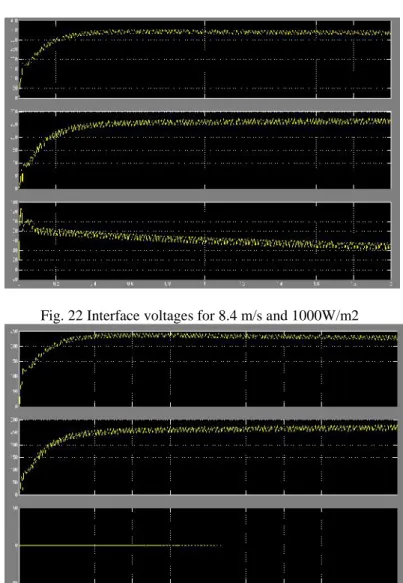
Fig. 22 Interface voltages for 8.4 m/s and 1000W/m2
Fig. 23 Interface voltages for 0 m/s and 200W/m2
Conclusion
In this paper a double-port interface has been presented. The specific of this interface consist on naturally series connection of the outputs of the two different dc/dc converter. The system is stable and there is no interference between the two input converters. Using the data for a 1 kW PV system and 1.5 kW wind generator, the simulation results shown and extended power capability even for partial operating conditions and thus greater energy stored. Hence, this system is recommended for small scale stand-alone renewable energy system.
References
[1] Z. Liang, R. Guo. J. Li and A.Q. Huang, A High-Efficiency PV Module-Integrated DC/DC Converter for PV Energy Harvest in FREEDM Systems, IEEE Transaction on Power Electronics, Vol. 26, No. 3, March 2011, pp. 897-909
[2] R. Bilinton and R. Karki, Capacity Expansion of Small Isolated Power Systems Using PV and Wind Energy, IEEE
Transaction on Power Systems, Vol. 16, No. 4, Nov. 2001, pp.
892-897
[3] K. Sun, Li Zang, Yun Xing and J.M. Guerrero, A Distributed Control Strategy Based on DC Bus Signaling for Modular Photovoltaic Generation Systems With Battery Energy Storage,
IEEE Transaction on Power Electronics, Vol. 19, No. 26, Oct.
2011, pp. 3032-3045
[4] H.-J. Chin, Y.-K. Lo, C.-J. Yao, T.-P. Lee, J.-M. Wang and J.- X. Lee, A Modular Self-Controlled Photovoltaic Charger With InterIntegrated Circuit (I2C) Interface, IEEE Transaction
on Energy Conversion, Vol. 26, No. 1, March 2011, pp. 281-289
[5] Z. Qian, O.Abdel-Rahman, C. Hamilton, M. Batarseh and I. Batarseh, An Integrated Four-Port Converter for Compact and Efficient Hybrid Power Systems, IEEE Proceedings for International Symposium on Circuits and Systems, June 2010,
pp. 2307-2210
[6] S. Kumaravel and S. Ashok, Design and Analysis of Multiple Input Power Conditioner for Solar PV/Wind Hybrid Energy System, IEEE TENCON Conference, Nov. 2011, pp.883-887 [7] W. Jiang and B. Fahimi, Multiport Power Electronic Interface–Concept, Modeling and Design, IEEE Transaction on
Power Electronics, Vol. 26, No. 7, July 2011, pp. 1890-1900
[8] J.J. Nedumgatt, K.B. Jaykrisham, S. Umashankar, D. Vijayakumar and D.P. Kothari, Perturb and Observe MPPT Algorithm for Solar PV System – Modeling and Simulation,
Annual IEEE India Conference (INDICON), Dec. 2011
[9] Y.-L. Juan, An Integrated-Controlled AC/DC Interface for Microscale Wind Power Generation Systems, IEEE Transaction