Design And Structural Analysis Of High Speed Helical Gear
Using ANSYS
1Dadi vijay 2Sanmala Rajasekhar 3Md Inaithulrehman 1M.Tech student
2,Associate Professor,3,Assistant Professor 123Department of Mechanical Engineering
Kakinada Institute Of Technology And Science, Divili.
Abstract: Marine motors are among substantial obligation hardware, which should be dealt with in the most ideal path amid model improvement stages. These motors are worked at high speeds which incite substantial anxieties and diversions in the riggings and in other turning parts. For the sheltered working of the motor, these anxieties and redirections must be minimized. In this venture, static-basic examination on a rapid helical apparatus utilized as a part of marine motors, have been performed. The measurements of the model have been landed at by hypothetical strategies. The anxieties created and the redirections of the tooth have been broke down for various materials. At long last the outcomes acquired by hypothetical examination and Finite Element Analysis are contrasted with check the accuracy. A conclusion has been landed on the material which is most appropriate for the marine motors in view of the outcomes
1. Introduction
Equipping is a standout amongst the best techniques transmitting force and rotating movement from the source to its application with or without alter of speed or course. Apparatuses will win as a basic machine component for transmitting power in future machines because of their high level of unwavering quality and conservativeness. The fast improvement of substantial businesses, for example, vehicle, shipbuilding and airplane ventures require propelled utilization of rigging innovation. A gearbox comprises of an arrangement of riggings, shafts and direction that are mounted in an encased greased up lodging. They are accessible in a wide scope of sizes, limits and speed proportions. Their capacity is to change over the info gave by the prime mover into a yield with lower speed and relating higher torque. In this proposal, examination of the qualities of helical riggings in a gearbox is contemplated utilizing limited component analysis.The
critical prerequisite of compelling force transmission in different machines, vehicles, lifts, generators, and so forth has made an expanding interest for more precise investigation of the attributes of apparatus frameworks. For example in car industry exceedingly solid and lightweight riggings are fundamental. Besides the most ideal approach to reduction of commotion in motor requires the creation of hush rigging framework. Clamor decrease in apparatus sets is particularly basic in the quickly developing today's innovation since the workplace is gravely affected by commotion. The best method for rigging clamor diminishment is achieved by diminishing of vibration related with them. The lessening of clamor by vibration control can be accomplished through an exploration try by a specialist in the field.
2. GEARS
International Journal of Science Engineering and Advance Technology,
IJSEAT, Vol. 4, Issue 4
ISSN 2321-6905
APRIL-2016
and different systems. Primitive riggings appeared in Fig. 1 were initially utilized as a part of entryway drive instrument in sanctuaries and surrenders, and water lifting components 2600 B.C. in India and somewhere else
.
Fig.No 1: Primitive gears made of wood
2.1Helical Gear
Fig.No 2: Helical Gear
Helical apparatuses are utilized for parallel shaft drives. They have teeth slanted to the pivot as appeared in Hence for a similar width; their teeth are longer than goad adapts and have higher load conveying limit. Their contact proportion is higher than goad gears and hello
One of the best strategies for transmitting power between the poles is riggings. Riggings are generally used to transmit torque and rakish speed. The quick improvement of businesses, for example, vehicle, shipbuilding and airplane require propelled utilization of apparatus innovation. Clients incline toward autos with exceptionally effective motor. This required up an interest for very power transmission. Vehicle divisions are one of the biggest makers of riggings. Higher unwavering quality and lighter weight apparatuses are important to make vehicle light in weight as lighter cars keep on being sought after. The most ideal method for transmitting power between the poles is riggings. Riggings are generally used to transmit torque and rakish speed. The outline of apparatus is an intricate procedure. For the most part it needs vast number of cycles and information sets. Much of the time outfit configuration is conventional and determined by various sorts of models
fundamental strides required in this work are depicted as take after:
•Modeling the rigging without losing its geometry in CREO-2 programming.
•Generate the profile of helical apparatus teeth model to ascertain the impact of rigging bowing, utilizing three-dimensional model and contrast the outcomes and adjusted Lewis hypothesis.
•Develop and decide models of contact components, to examination contact stresses utilizing
fig.no 3.illustration of concept of helical gear
3. Helical gear
–
Geometry and
Nomenclature
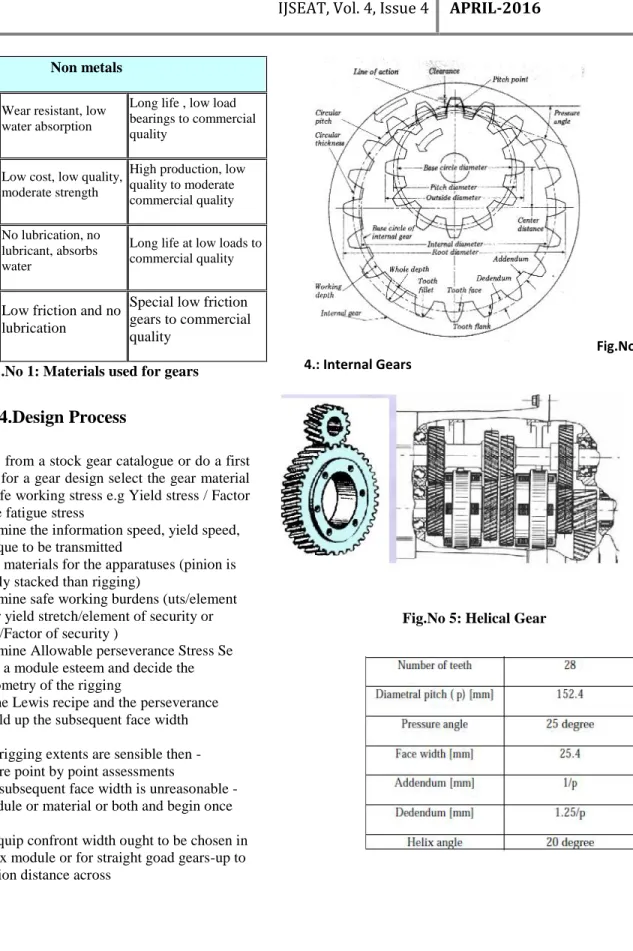
The helix angle ψ, is always measured on the cylindrical pitch surface Fig. 11.8. ψ value is not standardized. It ranges between 15º and 45º. Commonly used values are 15, 23, 30 or 45º. Lower values give less end thrust. Higher values result in smoother operation and more end thrust. Above 45º is not recommended. The circular pitch (p) and pressure angle (Ø) are measured in the plane of rotation, as in spur gears. These quantities in normal plane are denoted by suffix n (pn, Øn) as shown in Fig. 4
Figure 4: Portion of helical rack
3.1Materials used for gears
Mild steel is a poor material for gears as it has poor resistance to surface loading. The carbon content for unhardened gears is generally 0.4 % (min) with 0.55 % (min) carbon for the pinions. Dissimilar materials should be used for the meshing gears - this particularly applies to alloy steels. Alloy steels have superior fatigue properties compared to carbon steels for comparable strengths. For extremely high gear loading case hardened steels are used the surface hardening method employed should be such to provide sufficient case depth for the final grinding process used.
Material Notes applications
Ferrous metals
Cast Iron
Low Cost easy to machine with high damping
Large moderate power, commercial gears
Cast Steels
Low cost, reasonable strength
Power gears with medium rating to commercial quality
Plain-Carbon Steels
Good machining, can be heat treated
Power gears with medium rating to commercial/medium quality
Alloy Steels
Heat Treatable to provide highest strength and durability
International Journal of Science Engineering and Advance Technology,
IJSEAT, Vol. 4, Issue 4
ISSN 2321-6905
APRIL-2016
Non metals
Acetal (Delrin Wear resistant, low water absorption
Long life , low load bearings to commercial quality
Phenolic laminates
Low cost, low quality, moderate strength
High production, low quality to moderate commercial quality
Nylons
No lubrication, no lubricant, absorbs water
Long life at low loads to commercial quality
PTFE Low friction and no lubrication
Special low friction gears to commercial quality
Table .No 1: Materials used for gears
4.Design Process
To select gears from a stock gear catalogue or do a first approximation for a gear design select the gear material and obtain a safe working stress e.g Yield stress / Factor of Safety. /Safe fatigue stress
• Determine the information speed, yield speed, proportion, torque to be transmitted
• Select materials for the apparatuses (pinion is more profoundly stacked than rigging)
• Determine safe working burdens (uts/element of wellbeing or yield stretch/element of security or Fatigue quality/Factor of security )
• Determine Allowable perseverance Stress Se • Select a module esteem and decide the subsequent geometry of the rigging
• Use the Lewis recipe and the perseverance equation to build up the subsequent face width
• If the rigging extents are sensible then -continue to more point by point assessments
• If the subsequent face width is unreasonable -change the module or material or both and begin once more
• The equip confront width ought to be chosen in the range 9-15 x module or for straight goad gears-up to 60% of the pinion distance across
Fig.No 4.: Internal Gears
Table.No .2: Gear parameter 30 teeth
5.CAD-Design Tool
PC helped plan (CAD), otherwise called PC supported outline and drafting (CADD), is the utilization of PC innovation for the procedure of plan and plan documentation. PC Aided Drafting depicts the way toward drafting with a PC. CADD programming, or situations, gives the client input-devices with the end goal of streamlining configuration forms; drafting, documentation, and assembling forms. CADD yield is frequently as electronic records for print or machining operations. The improvement of CADD-based programming is in direct connection with the procedures it looks to streamline; industry-based programming (development, producing, and so on.) normally utilizes vector-based (straight) situations while realistic based programming uses raster-based (pixilated) environments.CADD situations regularly include more than just shapes. As in the manual drafting of specialized and building drawings, the yield of CAD must pass on data, for example, materials, procedures, measurements, and resiliences, as indicated by application-particular conventions.CAD might be utilized to configuration bends and figures in two-dimensional (2D) space; or bends, surfaces, and solids in three-dimensional (3D) objects.
6. MODELING OF HELICAL GEAR
Creo isafamilyor,suiteof design,software supporting item outline for discrete makers and is created by PTC. PTC Creo is a versatile, interoperable suite of item plan programming that conveys quick time to esteem. It helps groups make, investigate, view and influence item plans downstream using 2D CAD, 3D CAD, parametric and coordinate modeling.PTC Creo Parametric gives the broadest scope of capable yet adaptable 3D CAD abilities to quicken the item improvement prepare. Via computerizing errands, for example, making building drawings, we can keep away from blunders and spare
noteworthy time. The product likewise gives us a chance to perform investigation, make renderings and activitys, and upgrade profitability over a full scope of other mechanical outline errands, including a check for how well our plan complies with best practices. PTC Creo Parametric empowers us to plan higher-quality items speedier and permits us to convey all the more proficiently with assembling, providers
7.
INTRODUCTION TO FEA
Limited Element Analysis (FEA) was initially created in 1943 by R. Courant, who used the Ritz technique for
Table.No .2: Gear parameter 30 teeth
5.CAD-Design Tool
PC helped plan (CAD), otherwise called PC supported outline and drafting (CADD), is the utilization of PC innovation for the procedure of plan and plan documentation. PC Aided Drafting depicts the way toward drafting with a PC. CADD programming, or situations, gives the client input-devices with the end goal of streamlining configuration forms; drafting, documentation, and assembling forms. CADD yield is frequently as electronic records for print or machining operations. The improvement of CADD-based programming is in direct connection with the procedures it looks to streamline; industry-based programming (development, producing, and so on.) normally utilizes vector-based (straight) situations while realistic based programming uses raster-based (pixilated) environments.CADD situations regularly include more than just shapes. As in the manual drafting of specialized and building drawings, the yield of CAD must pass on data, for example, materials, procedures, measurements, and resiliences, as indicated by application-particular conventions.CAD might be utilized to configuration bends and figures in two-dimensional (2D) space; or bends, surfaces, and solids in three-dimensional (3D) objects.
6. MODELING OF HELICAL GEAR
Creo isafamilyor,suiteof design,software supporting item outline for discrete makers and is created by PTC. PTC Creo is a versatile, interoperable suite of item plan programming that conveys quick time to esteem. It helps groups make, investigate, view and influence item plans downstream using 2D CAD, 3D CAD, parametric and coordinate modeling.PTC Creo Parametric gives the broadest scope of capable yet adaptable 3D CAD abilities to quicken the item improvement prepare. Via computerizing errands, for example, making building drawings, we can keep away from blunders and spare
noteworthy time. The product likewise gives us a chance to perform investigation, make renderings and activitys, and upgrade profitability over a full scope of other mechanical outline errands, including a check for how well our plan complies with best practices. PTC Creo Parametric empowers us to plan higher-quality items speedier and permits us to convey all the more proficiently with assembling, providers
7.
INTRODUCTION TO FEA
International Journal of Science Engineering and Advance Technology,
IJSEAT, Vol. 4, Issue 4
ISSN 2321-6905
APRIL-2016
numerical investigation and minimization of variational math to get rough answers for vibration frameworks. Presently, a paper distributed in 1956 by M. J. Turner, R. W. Clough, H. C. Martin, and L. J. Topp built up a more extensive meaning of numerical examination. The paper fixated on the "solidness and diversion of complex structures".
By the mid 70's, FEA was restricted to costly centralized computer PCs by and large possessed by the flight, car, guard, and atomic ventures. Since the quick decrease in the cost of PCs and the remarkable increment in registering power, FEA has been created to an inconceivable accuracy. Display day supercomputers are currently ready to create precise outcomes for a wide range of parameters.
FEA comprises of a PC model of a material or plan that is pushed and broke down for particular outcomes. It is utilized as a part of new item outline, and existing item refinement. An organization can check a proposed configuration will have the capacity to perform to the customer's determinations preceding assembling or development. Altering a current item or structure is used to qualify the item or structure for another administration condition.In instance of basic disappointment, FEA might be utilized to decide the plan changes to meet the new condition.
8.ANSYS
ANSYS is an Engineering Simulation Software (PC supported Engineering). Its instruments cover Thermal, Static, Dynamic, and Fatigue limited component investigation alongside different devices all intended to help with the improvement of the product.The organization was established in 1970 by Dr. John A. Swanson as Swanson Analysis Systems, Inc. SASI. Its main role was to create and advertise limited component examination programming for basic material science that could reproduce static (stationary), dynamic (moving) and warmth exchange (warm) issues. SASI built up its business in parallel with the development in PC innovation and designing needs. The organization developed by 10 percent to 20 percent every year, and in 1994 it was sold. The new proprietors took SASI's driving programming, called ANSYS®, as their lead item and assigned ANSYS, Inc. as the new organization
9. RESULTS
ANALYSIS RESULTS OF HELICAL GEAR
Fig.No 7:Meshed of helical gear
9.Gear having 30 teeth
10.Gear having 37teeth
9.2 RESULT AND DISCUSSION
Confront width and helix point are imperative geometrical parameters in deciding the condition of worries amid the outline of apparatuses. Consequently, the target of this work is to lead a parametric review by fluctuating the face width to concentrate their impact on the twisting worry of helical apparatus. So as to decide the burdens variety with the face width five unique models of helical were made by keeping different parameters (i.e. module, pitch circle breadth, number of teeth, helix edge and so forth) consistent. Table II underneath demonstrates the aftereffects of twisting worry with the variety in the face width of the helical rigging tooth.
Table.No 3: 28 teeth AGMA & ANSYS Difference
Table.No 4: 30 teeth AGMA & ANSYS Difference 0
10 20 30 40 50 60 70
1 2 3
TEETH AGMA ANSYS
0 20 40 60 80 100 120
International Journal of Science Engineering and Advance Technology,
IJSEAT, Vol. 4, Issue 4
ISSN 2321-6905
APRIL-2016
The table above unmistakably demonstrates that as the face width is expanding there is a comparing diminish in the estimation of the tooth bowing worries of a helical apparatus figured from the AGMA and additionally that acquired from ANSYS examination. Accordingly, from the outcomes acquired we can state that for any steady load and speed, the apparatus with higher face width is reasonable. Fig. 5 demonstrates the Graph of Bending Stress [MPa] against Face width [mm]
11.CONCLUSION
Most extreme bowing anxiety happened in the upper portion of the helical apparatus .in principle of helical Gear, we are thinking about that the heap is acting at one point and the anxiety is computed. The estimation of most extreme worries in a helical rigging at tooth root is three dimensional issues. The precise assessment of stress state is intricate errand. The commitment of this theory work can be abridged as takes after:
The quality of helical apparatus tooth is a urgent parameter to counteract disappointment. In this work, it is demonstrated that the powerful strategy to appraise the root bowing anxiety utilizing three dimensional model of a helical rigging and to check the exactness of this technique the outcomes with various face width of teeth are contrasted and hypothetical and AGMA equations.
The confront width is an essential geometrical parameter in outline of helical apparatus as it is normal in this work the most extreme bowing anxiety diminishes with expanding face width. From the outcomes we can reason that ANSYS can likewise be utilized for anticipating the benefits of twisting worry at any required face width which is much less demanding to use to take care of complex outline issues like riggings.
References
[1]. Yonatan, F., Variable Mesh Stiffness of Spur Gear Teeth Using FEM, M.sc. thesis Department of mechanical Engineering, Addis Ababa University
[2]. Tsay, C.B., and Fong, Z.H., Computer Simulation
[4]. Vijayarangan, S., and Ganesan, N., A Static Analysis of Composite Helical Gears Using Three-dimensional Finite Element Method, Computers & Structures, 49,pp.253- 268,1993.
[5]. Maitra, G.M, Hand Book of Gear Design, TataMcGraw-Hill, New Delhi, 2004.
[6]. Rao, C.M., and Muthuveerappan G., Finite Element Modeling and Stress Analysis of Helical Gear, Teeth, Computers & structures, 49,pp.1095-1106, 1993.
[7]. Singiresu S. Rao “The Finite Element Method in Engineering”.
[8]. Lu, J., Litivin, F., and Chen, J.S., Load Share and Finite Element Stress Analysis for Double Circular-Arc Helical Gears, Mathl.Comput.Modeling, 21,pp.13-30.1995.
[9]. Orthwein, W.C., Machine Component Design, Jauo publishing House, Mumbai, 2004.
[10]. Jianfeng L., Mingtain, X., and Shouyou, W., Finite Element Analysis of Cylindrical Gears, Communication in Numerical Methods in Engineering, 14, pp.963-975, 1998.
[11]. Condoor, S., Modeling using pro/Engineer Wildfire 2.0, SDC, 2004.