High-Q nested resonator in an actively stabilized optomechanical cavity
F. M. Buters, K. Heeck, H. J. Eerkens, M. J. Weaver, F. Luna, S. de Man, and D. Bouwmeester
Citation: Appl. Phys. Lett. 110, 104104 (2017);
View online: https://doi.org/10.1063/1.4978212
View Table of Contents: http://aip.scitation.org/toc/apl/110/10
Published by the American Institute of Physics
Articles you may be interested in
Current-induced surface roughness reduction in conducting thin films
Applied Physics Letters 110, 103103 (2017); 10.1063/1.4977024
Theoretical and experimental investigations of acoustic waves in embedded fluid-solid multi-string structures
Applied Physics Letters 110, 101906 (2017); 10.1063/1.4977937
Growth of Fe3Si/Ge/Fe3Si trilayers on GaAs(001) using solid-phase epitaxy
Applied Physics Letters 110, 102103 (2017); 10.1063/1.4977833
All metalorganic chemical vapor phase epitaxy of p/n-GaN tunnel junction for blue light emitting diode applications
Applied Physics Letters 110, 102104 (2017); 10.1063/1.4978268
Electrically driven and electrically tunable quantum light sources
Applied Physics Letters 110, 071102 (2017); 10.1063/1.4976197
Nanosecond magnetization dynamics during spin Hall switching of in-plane magnetic tunnel junctions
High-Q nested resonator in an actively stabilized optomechanical cavity
F. M.Buters,1,a)K.Heeck,1H. J.Eerkens,1M. J.Weaver,2F.Luna,2S.de Man,1 and D.Bouwmeester1,2
1
Huygens-Kamerlingh Onnes Laboratorium, Universiteit Leiden, 2333 CA Leiden, The Netherlands
2
Department of Physics, University of California, Santa Barbara, California 93106, USA
(Received 24 January 2017; accepted 23 February 2017; published online 7 March 2017)
Experiments involving micro- and nanomechanical resonators need to be carefully designed to reduce mechanical environmental noise. A small scale on-chip approach is to add a resonator to the system as a mechanical low-pass filter. However, the inherent low frequency of the low-pass filter causes the system to be easily excited mechanically. We solve this problem by applying active feedback to the resonator, thereby minimizing the motion with respect to the front mirror of an optomechanical cavity. Not only does this method actively stabilize the cavity length but it also retains the on-chip vibration isolation.Published by AIP Publishing.
[http://dx.doi.org/10.1063/1.4978212]
Micro- and nanomechanical systems are widely used for precision measurements across a variety of research topics, see Ref. 1 for an overview. In cavity optomechanics for example, electromagnetic radiation is used to perform dis-placement measurements that beat the standard quantum limit.2,3Similarly, in atomic force microscopy (AFM), forces as small as 1018N are measurable.4
A common challenge when using mechanical resonators is achieving a high mechanical quality factor (Q-factor) and shielding from vibrational noise. Recently, clamping losses or coupling to external mechanical modes has been identified as a major source of loss in mechanical systems,5–7affecting both the mechanical Q-factor and the amount of vibrational noise entering the system. A solution to this problem is to introduce phononic crystals8,9and low frequency mechanical resonators10–12to isolate the device from the environment.
Surrounding the resonator of interest with an additional low frequency resonator has a severe drawback. The addi-tional low frequency resonator itself can be mechanically excited by the environment. The obvious solution would be to fixate the additional resonator, but this will remove the effect of the mechanical low-pass filter. Typically, this trade-off is circumvented by reducing the motion of the additional resonator using active feedback cooling.
Active feedback cooling, also called cold damping, uses the real time displacement of the mechanical resonator to apply a suitable feedback signal to an actuator (mechanical, optical, or electrical).13–19 Increasing the gain of the feed-back signal to the actuator results in more feedfeed-back cooling up to the point where the amplified read-out noise causes the mechanical motion to increase.
In this article, we will first demonstrate active feedback cooling of our nested trampoline resonator.12 Because this resonator is part of an optomechanical cavity, a more elegant approach to solving this problem is possible. We will show how, by actively stabilizing the position of the resonator with respect to the front mirror of the cavity, all length varia-tions of the cavity are eliminated, including the motion of
the low frequency resonator while retaining the on-chip vibration isolation.
For the actuation, we make use of the dielectric force. This is convenient as any dielectric body in the presence of an electric field gradient experiences a dielectric force.20 Recently, this method was also used to demonstrate control of micro- and nanomechanical resonators.21,22
The energy of a dipole in an electric field isU¼ pE. The force the dipole experiences is F¼ rU¼ ðp rÞE. With the dipole moment p¼aE, this can be written as F¼ ðaE rÞE. The strength of the dielectric force depends therefore on the applied electric field, its gradient, and the polarizability of the medium. Although the nested resonator is largely made from silicon, which is weakly polarizable, the experiment is carried out in a vacuum, so relatively large electric fields can be generated. For example, a back-of-the-envelope calculation using a charged sphere placed lm distance behind our sample23 shows that forces up to lN are feasible.
We realize an electric field gradient by placing a small ring electrode behind the nested resonator, as depicted in Fig. 1. The typical distance between the electrode and the resonator is 500lm. Both a bias voltage and a modulation voltage are applied. Since the electric field is linear in applied voltage, the dielectric force can be written as F ¼bV2 ¼bðVd
:c:þVa:c:Þ2bVd2:c:þ2bVd:c:Va:c:, in the limit
when the applied biasVd:c:is much larger than the modula-tion Va:c:, withbbeing some constant. Note that the force is
now linear in Va:c:; therefore, a modulation at frequency f0
will result in a force at frequency f0.
The read-out of the mechanical motion is done in three different ways. A single-mode (SM) fiber is located approx. 500lm behind the mass of the outer resonator to form a fiber interferometer,25as shown in Fig.1. The interference signal created by the light reflecting off the outer resonator and the light reflected off the fiber facet allows for a sensitive read-out of the resonators motion. Our home-built fiber interfer-ometer using a standard distributed feedback laser diode at 1550 nm reaches a read-out sensitivity of approx. 300 fm=pffiffiffiffiffiffiHzaround 3.5 kHz.
a)
buters@physics.leidenuniv.nl
For the second read-out method, a low finesse (F¼300) Fabry-Perot cavity, 5 cm long operating around 980 nm, is used. The transmitted cavity light is collected using a multi-mode (MM) fiber placed in the center behind the sample as shown in Fig.1.
The third method uses the same Fabry-Perot cavity together with a wavelength of 1064 nm to create a high finesse (F170 00) cavity. The Pound-Drever-Hall method26 is used to read out the displacement of this cavity from the light reflecting off the cavity. Finally, the whole set-up resides in a vibration isolated vacuum chamber with a base pressure of 103mbar to eliminate the effect of gas damping on the mechanical properties.
As a demonstration of the actuation via the dielectric force, the mechanical transfer function of the nested resona-tor is measured. The frequency of the applied force to the outer resonator is varied via the reference output of a lock-in amplifier and the response of the inner resonator is measured using the low finesse optical cavity together with the same
lock-in amplifier. The data (blue points) of Fig.2follow the theory curve for two coupled harmonic oscillators. At the frequency of the inner resonator, which for this sample is 292.5 kHz, more than 60 dB of isolation is provided via the nested resonator design. This is consistent with previous findings.12 The inset shows that the inner resonator can be driven in this way as well. Note that this measurement assumes a constant force excitation which, judging by the agreement between experiment and theory of Fig.2, is valid. Therefore, the bandwidth of this method of actuation is at least 100 kHz.
The main point of the addition of a dielectric force is not to drive the outer resonator but to reduce its motion. To do so, we use the method of active feedback cooling.13The dis-placement signal from the fiber interferometer is sent through a differentiating circuit and is amplified with a variable gain amplifier (see Fig.1). Together with a DC voltage, the signal is then sent to the ring electrode to provide a damping force for the motion of the outer resonator. To avoid difficulty in interpreting the data,19 we use an out-of-loop measurement provided by the low finesse cavity to read out the effect of the feedback.
From the mechanical noise spectrum obtained via the cavity read-out, the effective mechanical Q-factor of the outer resonator is determined together with the total dis-placementhx2iby fitting a Lorentzian. Via the equipartition theorem the effective temperature can be calculated using
T ¼ hx2iMX2
m=kb with kb the Boltzmann constant, M¼7 107kg, and Xm¼2p3488 rad/s for this particular
sample.
With the feedback circuit activated, the motion of the resonator will be both damped and cooled. Increasing the gain results in more damping and cooling of the mechanical motion up to the point where the amplified detection noise becomes comparable to the thermal noise. The amplified read-out noise from the feedback is transferred to the mechanical motion of the resonator, causing the effective temperature to increase again. We have observed precisely this behavior, as shown in Fig. 3. Note that this is visible because of the out-of-loop measurement. Measuring the mechanical noise spectrum via the interferometer, within the feedback loop, will result in noise squashing.19
FIG. 1. Schematic overview of the geometry for applying an electric field gra-dient. A ring electrode, single-mode (SM) fiber and multi-mode (MM) fiber are placed behind the resonator. The resonator itself is part of an optomechan-ical Fabry-Perot cavity. Either the output from the fiber interferometer or the Pound-Drever-Hall error signal is used to drive the high voltage amplifier con-nected to the ring electrode. More details of the optical set-up can be found in Ref.24. Inset: optical image of the nested resonator, which consists of an inner trampoline resonator surrounded by a larger outer resonator.
FIG. 2. The mechanical transfer function of the nested resonator design measured by applying an electrostatic force to the outer resonator and read-ing out the response of the inner resonator via the cavity. Inset: Driven response of the inner resonator.
FIG. 3. Active feedback cooling of the outer resonator. When the gain is increased, both the effective temperature and the Q-factor decrease. For large gains, the amplified read-out noise actually drives the outer resonator, increasing the effective temperature. (a) Selection of power spectra demon-strating cooling of the mechanical mode. This out-of-loop measurement uses the read-out via the low finesse cavity. Note that a small additional resonance is visible. (b) Effective mode temperature as a function of mechanical Q.
We are able to reduce the intrinsic Q-factor of 90 000 to about 20, limited only by the gain of the amplifier. The mechanical mode temperature is reduced to about 15 K using this form of cooling. To check if the limiting factor of the mode temperature is indeed the noise floor of the interfero-metric read-out, the data are fitted using the following expression19
Teff¼
TbathQ
Q0
þkXmðQQ0Þ
2
4kbQ20Q
Sxn; (1)
withTbath the environmental temperature,Qthe quality factor,
kthe spring constant, Q0the intrinsic quality factor, and Sxn the read-out noise power. In our case:k¼340 N/m,Tbath¼ 293 K, andQ0¼90 000. The only free parameter is the read-out noise power Sxn. From the fit (red curve Fig. 3(b)), we obtain a value for ffiffiffiffiffiffiSxn
p
¼380610 fm=pffiffiffiffiffiffiHz, which is close to the noise floor of our interferometric read-out.
Using active feedback, the total rms displacement is reduced from 6 pm to 0.8 pm, which for most applications is sufficient. However in our case, we require further reduction of the motion. To achieve this, the interferometric read-out is replaced with a more sensitive read-out method using a high finesse optical cavity.
The use of a high finesse optical cavity typically requires a means to keep laser and cavity resonant. Usually, the laser frequency is continuously adjusted to keep it resonant with the cavity mode. An alternative method would be to adjust the cavity length to keep the cavity resonant with the laser. For the set-up depicted in Fig.1, the cavity lengthLcan be varied by changing the position of the outer resonator using the dielectric force, while tracking the cavity resonance via the Pound-Drever-Hall (PDH) method.26 In this way, the nested resonator design not only mechanically decouples the inner resonator from the environment but also stabilizes the cavity length with respect to the laser frequency.
In Fig. 4(a), the typical PDH error signal (blue) is obtained by scanning the cavity length using a high voltage amplifier (red). Note that to ensure a linear response, a DC bias voltage (not shown here) is also added. The displace-ment of the outer resonator is observed via the interferome-ter, as shown in Fig. 4(b). A displacement of 61.5 nm provides sufficient range to keep the cavity resonant with the laser.
We typically require a feedback bandwidth of about 10 kHz to keep laser and cavity resonant. However, the
mechanical resonance atf¼3488 Hz provides a very rapidp
phase shift in the transfer function. A notch filter is placed at
f¼3.4 kHz in the feedback loop to smooth this transition. A second notch filter atf ¼10:2 kHz is used to compensate the first higher order mechanical mode.
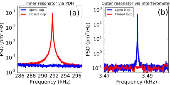
When the feedback loop is closed, the cavity should remain resonant with the laser. Therefore, the motion of the inner resonator, which occurs at a frequency beyond the feedback bandwidth, should be visible in the PDH error sig-nal. Fig.5(a)shows the Fourier transform of this error signal and indeed, with a closed loop, the thermal motion of the inner resonator is visible. The thermal motion of the outer resonator has been mostly eliminated and is no longer visible via the interferometric read-out, see Fig.5(b).
From Fig.5, it is clear that the feedback not only works but also that the on-chip isolation still works as evidenced by the clean spectrum of Fig.5(a). However, what has happened to the motion of the outer resonator? Effectively, with active stabilization, a very strong electrical spring is placed between the outer resonator and the front mirror. The only way for the outer resonator to move at a particular frequency is if the front mirror also moves at this frequency. This stiffening of the outer resonator explains why, with a closed loop, the mechanical motion is no longer visible in Fig.5(b). The addi-tional electrical spring also helps to prevent any unwanted optical spring effects27present in an optomechanical cavity.
In conclusion, we have demonstrated how to solve the problem of fixating an on-chip mechanical low-pass filter while retaining the mechanical isolation. By making use of an optomechanical cavity, the motion of the resonator can be referenced to the front mirror. Not only does this stabilize the cavity with respect to the laser, it also stiffens the resona-tor, thereby significantly reducing its motion. We have made use of an optomechanical system, but in principle the techni-ques presented in this work can be applied to any system as long as a suitable reference can be chosen.
The authors acknowledge the useful discussions with W. Loeffler. The authors would also like to thank H. van der Meer for technical assistance and support.
1K. Ekinci and M. Roukes,Rev. Sci. Instrum.76, 061101 (2005). 2
J. Hertzberg, T. Rocheleau, T. Ndukum, M. Savva, A. Clerk, and K. Schwab,Nat. Phys.6, 213 (2010).
3J. Suh, A. J. Weinstein, C. U. Lei, E. E. Wollman, S. K. Steinke, P.
Meystre, A. A. Clerk, and K. C. Schwab,Science344, 1262 (2014). FIG. 4. Scanning of the cavity length (a) Varying the position of the outer
resonator results in the typical PDH error signal. (b) The displacement of the outer resonator is monitored using the fiber interferometer.
4G. Binnig, C. F. Quate, and C. Gerber, Phys. Rev. Lett. 56, 930 (1986).
5
G. D. Cole, I. Wilson-Rae, K. Werbach, M. R. Vanner, and M. Aspelmeyer,Nat. Commun.2, 231 (2011).
6I. Wilson-Rae, R. Barton, S. Verbridge, D. Southworth, B. Ilic, H.
Craighead, and J. Parpia,Phys. Rev. Lett.106, 047205 (2011). 7
P.-L. Yu, T. Purdy, and C. Regal,Phys. Rev. Lett.108, 083603 (2012). 8T. P. M. Alegre, A. Safavi-Naeini, M. Winger, and O. Painter, Opt.
Express19, 5658 (2011). 9
P.-L. Yu, K. Cicak, N. Kampel, Y. Tsaturyan, T. Purdy, R. Simmonds, and C. Regal,Appl. Phys. Lett.104, 023510 (2014).
10E. Serra, A. Borrielli, F. Cataliotti, F. Marin, F. Marino, A. Pontin, G.
Prodi, and M. Bonaldi,Phys. Rev. A86, 051801 (2012). 11
G. M. Harry and L. S. Collaboration, Classical Quantum Gravity 27, 084006 (2010).
12M. J. Weaver, B. Pepper, F. Luna, F. M. Buters, H. J. Eerkens, G. Welker,
B. Perock, K. Heeck, S. de Man, and D. Bouwmeester,Appl. Phys. Lett. 108, 033501 (2016).
13
J. Milatz, J. Van Zolingen, and B. Van Iperen,Physica19, 195 (1953). 14H. Hirakawa, S. Hiramatsu, and Y. Ogawa, Phys. Lett. A 63, 199
(1977).
15P.-F. Cohadon, A. Heidmann, and M. Pinard,Phys. Rev. Lett. 83, 3174 (1999).
16
M. Pinard, P.-F. Cohadon, T. Briant, and A. Heidmann,Phys. Rev. A63, 013808 (2000).
17C. H. Metzger and K. Karrai,Nature
432, 1002 (2004). 18
D. Kleckner and D. Bouwmeester,Nature444, 75 (2006). 19
M. Poggio, C. Degen, H. Mamin, and D. Rugar, Phys. Rev. Lett.99, 017201 (2007).
20
J. C. Maxwell,Philos. Trans. R. Soc. London158, 643 (1868). 21
S. Schmid, M. Wendlandt, D. Junker, and C. Hierold,Appl. Phys. Lett.89, 163506 (2006).
22Q. P. Unterreithmeier, E. M. Weig, and J. P. Kotthaus,Nature458, 1001
(2009). 23
A. Bouwers and P. Cath, Philips Tech. Tijdschr.6, 274 (1941). 24
H. Eerkens, F. Buters, M. Weaver, B. Pepper, G. Welker, K. Heeck, P. Sonin, S. de Man, and D. Bouwmeester,Opt. Express23, 8014 (2015). 25D. Rugar, H. Mamin, and P. Guethner,Appl. Phys. Lett.
55, 2588 (1989). 26
E. D. Black,Am. J. Phys.69, 79 (2001). 27
T. Corbitt, Y. Chen, E. Innerhofer, H. M€uller-Ebhardt, D. Ottaway, H. Rehbein, D. Sigg, S. Whitcomb, C. Wipf, and N. Mavalvala,Phys. Rev. Lett.98, 150802 (2007).