Building Information Modeling (BIM): Site-Building Interoperability
Methods
A Master Thesis Submitted to the Faculty
Of the
Worcester Polytechnic Institute
In Partial fulfillment of the requirements for the Degree of Masters of Science
In
Interdisciplinary Construction Project Management By ______________________ Menglin Wang September 2011 Approved _________________________ ________________________
Prof. Guillermo Salazar, PhD Signature
Thesis Committee Members:
Prof. MingJiang Tao, PhD ________________________
Signature
Prof. Tahar El-Korchi, PhD ________________________
Abstract
Nowadays, many companies in the Architecture/Engineering/Construction (AEC)
industry are using Building Information Modeling (BIM) in achieving a faster,
sustainable and more economic project. Among the new developed concepts and BIM
applications, two of the concepts most frequently used with the support of BIM
technology in the planning, organization and scheduling of projects are 4D and 5D in
which a 3D model is tied to its time execution (4D) at any point in time and its
corresponding cost (5D). However, most of these applications concentrate on
modeling the building but it does not include a corresponding modeling of the site in
which the building is located. To date, there are few studies and systematic
implementation of the site and the building integrated into one BIM model. This site-building integrated model can also be conceptualized as ―6D BIM‖ model.
The benefit of integrating the site and building together into one model is that
the building is no longer treated in isolation of its surround site but incorporates
extremely helpful short-term and long-term information for the owner, designer, and
builder regarding site topography, landscaping, access roads, ground conditions and
the location of site utilities.
Major existing research and technology issues that are preventing this
site-building integration deal with functionality and interoperability of the BIM software,
different orientation and coordination of building model and site model.
The objectives of this thesis are to explore current organizational and
technological issues preventing this integration, to investigate a feasible method to
BIM concept to the site conditions.
The research has been conducted by an extensive review on the literature related
to the topic of interest published primarily by AEC. A review on current applications
of Geographic Information Systems (GIS) has also been included because of the
wider context provided by this technology to the specific topic of this research.
Related BIM software developed by three different vendors —has been discussed and
compared to determine the level of feasibility and operational features of
technological support necessary to implement the site-linked BIM model. A case
study based on the design and construction of the WPI Recreational & Sports Center,
currently under construction, was developed to explore and understand the details that
are involved in creating a new site model and to link it with the existing 3D building
model. What has been learned from the analysis of this case study is presented,
discussed and analyzed in terms of benefits and limitations.
Recommendations for future extensions from both the research aspect and the
technology support aspect finally presented. These include the creation of 3D BIM
Campus Map, which is one site model with several building models placed on it to
facilitate future planning of new building and/or maintenance and operation of the
Acknowledgements
I want to thank to all those who have helped me to finish this thesis.
I want to express my deepest gratitude to my adviser Prof. Guillermo F. Salazar from
the Worcester Polytechnic Institute; whose help, stimulating suggestions and
encouragement helped me throughout the whole research and writing of this thesis.
This thesis would not possibly have been finished without his valuable and patient
guidance.
Thanks to Prof. Mingjiang Tao for attending my presentation rehearsal, his valuable
suggestions helped me in building a clear logic of how to organize my paper and my
presentation.
Thanks to the Gilbane Construction team on the Recreation Center Project by
providing valuable drawings and as built information.
Last but not least, thanks to all my family and friends for sharing their ideas and
Table of Contents
Abstract ... 2 Acknowledgements ... 4 List of Figures ... 7 List of Tables ... 9 1. Introduction ... 10 2. Background ... 142.1 Building Information Modeling ... 15
2.2 GIS & the Construction Site ... 16
2.3 Specific Problems need to be solved ... 20
2.4 Current Application Issues & Technology Support ... 23
3. Technology Support — Feasible Methods to Create a Site-linked 3D Model ... 26
3.1 BIM Tools & Interoperability ... 26
3.2 Feasible Methods ... 28
3.2.1 Method 1 — Autodesk Revit Architecture ... 28
3.2.2 Method 2 — Revit Architecture & AutoCAD Civil 3D ... 30
3.2.3 Method 3— Bentley Products ... 31
3.2.4 Method 4 — ArchiCAD & Other BIM software ... 32
4. Case Study ... 35
4.1 Previous Related Study at WPI ... 36
4.2 General Project Information ... 38
4.3 Existing problems ... 40
4.4 Specific Concerned Issues & Proposed Solutions ... 42
4.4.1 Selection of the Appropriate Software ... 42
4.4.2 Define Existing Underground Site Condition— Utilities ... 47
4.4.3 Excavation ... 54
4.5 Additional Findings — BIM for Landscape ... 60
5. Conclusions — What BIM brought us on site? ... 63
5.1 Benefits ... 63
5.2 Limitations ... 66
5.2.1 Technology Support ... 66
6.1 Future Research Work ... 70
6.2 Future Application Work ... 70
6.3 From One Building & One Site to 3D Campus Maps ... 71
Bibliography ... 72
Appendix 1 — Process of Using ArchiCAD to Create a Topographic Surface (Graphisoft, 2011) ... 77
List of Figures
Figure 1: Three levels of GIS ... 17
Figure 2: Method 1 — Revit Architecture ... 29
Figure 3 Method 2 — Revit Architecture & AutoCAD Civil 3D ... 31
Figure 4: Method 3 — Bentley products ... 32
Figure 5: Method 4 — ArchiCAD & Other BIM Software ... 33
Figure 6 : MQP Work – Terrain Model from Front 1 ... 37
Figure 7 : MQP Work – Terrain Model from Front 2 ... 37
Figure 8: Case Study – BIM as Integrated Information Resource ... 40
Figure 9 : CAD Drawing – As Built Utility Information (Provided by Gilbane Inc., 2011) ... 42
Figure 10 : Procedure 1 – Create Toposurface in Revit ... 44
Figure 11 : Procedure 2 – Create Site Model in AutoCAD Civil 3D ... 45
Figure 12 : Groundwater observations wells plan by Haley & Aldrich’s Geotechnical Report 49 Figure 13: Structural Precast Concrete Bid Package C-3.0 (Cannon Design) ... 50
Figure 14: Example of Label from CAD as-built Drawings ... 51
Figure 15: Structural Precast Concrete Bid Package C-1.0 (Cannon Design) ... 52
Figure 16: Civil 3D Pipe Model – Example of Drainage Manhole ... 53
Figure 17: Civil 3D Pipe Model – Pipe Properties ... 53
Figure 18: Overall 3D Underground Utilities ... 54
Figure 19: “Preconstruction Phase” – Civil 3D Terrain Model ... 55
Figure 20: “Excavation Phase” – Civil 3D Site Model ... 56
Figure 21: “Excavation Phase” – Civil 3D Site Model, Shaded ... 57
Figure 22: Grading Volume Calculation Result ... 57
Figure 23: Site-linked BIM Model in Navisworks ... 59
Figure 24: Closer shot of the Site-linked BIM Model in Navisworks ... 60
Figure 25: Google Earth Picture... 79
Figure 26: Import Google Earth Surface into Civil 3D... 80
Figure 27: Bottom Surface ... 81
Figure 28: Bring CAD Information into Civil 3D ... 83
Figure 29: Creating Grading Group... 84
Figure 30: Define Grading Criteria ... 85
Figure 31: Whole Site Grading-1 ... 85
Figure 32: Whole Site Grading-2 ... 86
Figure 33: Grading Criteria--Whole Site ... 87
Figure 34: Grading—Excavation ... 87
Figure 35: Create pipe network ... 88
Figure 36: Create Drainage Pipe network ... 89
Figure 37: Structure Style-DMH ... 90
Figure 38: DMH 12& DMH 13 ... 90
Figure 39: DMH 12 Structure Properties—1 ... 91
Figure 42: Export DWF. Format in Revit ... 93
Figure 43: Project Information ... 93
Figure 44: Export DWF Files in Civil 3D ... 94
List of Tables
Table 1: BIM Tools & Interoperability ... 28 Table 2: Functionalities Comparison: Revit Architectural Vs. Revit MEP Vs. AutoCAD Civil 3D — based on graphic from Master Graphics, Inc. 9/23/2008 ... 46
1.
Introduction
It is attributed that the term ―BIM‖ was first coined in the late 1970s by Charles M.
Eastman and the concept of Building Information Modeling has been first used in the
mid-1980s (Eastman, 1975). Later definitions of this term include the one by Phil
Bernstein (Kiviniemi, 2010) and many others who have followed. However, the
theory of this concept has not been really applied in the
Architecture/Engineering/Construction (AEC) area until the recent 10 years (Yessios,
2004).
In today‘s AEC area, ―BIM‖ is no longer a strange word. Actually, it has become
more and more popular in different design and construction related areas. Some
people may still have confusions of what BIM really is by asking, is it just software?
Or it is a new CAD technology? But more and more people start to realize BIM is a
process of generating and managing building data during the building‘s life cycle (Lee,
et al., 2006). It is a revolutionary approach to design construction and maintenance
operations that promise to speed construction, improve collaboration among different
parties, control the cost of the change order, and reduce possible inefficiencies so that
the overall productivity can be enhanced (BIM at MSU, 2008).
Nowadays, more and more owners and Architecture/Engineering (AE) firms have
introduced the concept of BIM using 3D modeling to support both the preconstruction
and the construction process. Many new terms, concepts and BIM applications have
been developed such as 4D, 5D, 6D and 7D. The ―D‖ in the term of 3D BIM means ―dimension‖ and it has many different purposes for the construction industry.
3-Dimensional means the height, length and width. 4D BIM is 3D plus the factor of
schedule; 5D BIM is 4D plus cost estimation; 6D BIM is 5D plus site, which means a
3D building model linked with a 3D site model, and the integrated model should also
carry all the project schedule and estimation information; and even the concept of 7D
BIM has been brought up, which is BIM for life-cycle facility management (Review
of BIM, 2011).
Through a wider and wider application of BIM, certain benefits of using this
computer-aided technology have been found out and confirmed. The key benefit is its
accurate geometrical representation of the parts of building in an integrated data
environment allowing for a more coordinated production of documents in 2D and 3D,
it provides a better visualization of the design which would help the owner to confirm
if the final building would meet his/her expectations; meanwhile, BIM as an single
integrated information resource, would make the communication and coordination
among project participants much easier. Some other benefits of BIM are faster and
more effective processes, better design, controlled whole-life costs and environmental
data, better production quality, automated assembly, better customer service and
lifecycle data for facility management (Azhar, 2011).
As the benefits of using BIM being realized by people in the AEC industry, the
concepts of 3D, 4D and 5D BIM are more and more frequently used with the support
of BIM technology in the planning, organization and scheduling of projects. However,
most of the discussions associated with BIM are concentrating on modeling the
building solely, not much has been found regarding BIM for the corresponding site in
which the building is located. To date, there are few studies and systematic
implementation of integrating the site and building into one single model. The
benefits of using BIM concept to define site conditions are mentioned in some
on, what are the strength and weakness of doing so, what are the detailed feasible
methods of using BIM concept in defining site conditions and technology support that
we can use in the real world, not to mention the topic of linking site and building
model together.
The 6D BIM model, comparing to the 3D model, would carry the building
information as well as the necessary site data. This would require the integration of
Geographic Information System (GIS) and BIM. The GIS in this thesis would be
discussed from three different levels, from the whole world GIS to the mini GIS,
which is a site model with several building models on it, and then the scope would be
narrowed down to the topic of single site linked with single building. With the
integration of GIS, all the items in the site model would carry the exact location and
elevation information (X, Y, Z) as they are in the real construction world. And these
geographic data could coordinate with the orientation and elevation of the building
model, which would realize the final integration of the building and the site.
Thus, the objectives of this thesis are the following two: one is to explore current
organizational and technological issues preventing this integration and to investigate a
feasible method to create a site-linked BIM model; the other is to discuss the benefits
and limitations of bringing BIM concept to the site conditions.
The literature review for this paper contains both the broad topic of BIM and GIS, as
well as the specific topic of site-building integrated BIM model. Major resources are
books and journals published by American Society of Civil Engineers (ASCE), paper
and standards from Open Geospatial Consortium (OGC), also the white papers, news
reports from the BIM software vendors‘ websites such as Autodesk○R,Inc., Bentley
Systems and Graphisoft SE since the technology is changing rapidly in the
In addition, to explore and confirm what are the feasible methods of creating a
site-integrated BIM model, software products developed by different companies have
been considered, four procedures have been compared, the advantages and
disadvantages of each method were discussed. The WPI Sports and Recreation Center,
which is currently under construction, was selected as a case study to testify one of
the method — Revit Architecture and AutoCAD Civil 3D. In the case study, the
functionalities of different BIM software were listed and compared; Specific issues
regarding both the ground and underground site conditions were defined, and
corresponding solutions of using BIM were provided.
Benefits and limitations of the site-building integrated model were discussed as a
conclusion of what BIM has brought us on site. Future work were proposed from
three aspects, one is to continue research of the site model itself; the second is from
the aspect of applications, explore the method of using other software products to
create a site-linked BIM model; last but not the least, is to expend the research of
single site and building to the digital campus maps, which would be a site with several
2.
Background
Building Information Modeling (BIM), as one of the recent developments in the
architecture, engineering, and construction (AEC) industry,is no longer a strange
word. The model built by this technology, known as Building Information Model,
could be used for planning, design, construction and facility operation (Azhar, et al.
2008). This chapter presents a review of many publications on the broad topic of BIM,
as well as the specific topic of site-linked BIM. This review includes among others
books and journals published by American Society of Civil Engineers (ASCE), paper
and standards from Open Geospatial Consortium (OGC), which is a non-profit
international voluntary consensus standards organization that is leading the
development of standards for geospatial and location based services. The knowledge
base in this field is changing rapidly and there is new material that is constantly
published in the form of white papers, news reports from the BIM software vendors‘
websites such as Autodesk○R,Inc., Bentley Systems and Graphisoft SE.
This literature review is aimed to build a clear and systemic understanding about the
rapid evolution of BIM is in the AEC and Facility Management (FM) industries, as
well as how BIM has been evolving and applied from a global perspective. More
specifically, through the reading of these literatures it has been possible to learn how
much work has been done on this topic, what is still missing, what difficulties people
in these areas have met, what the major obstacles are and what specific problems that
2.1
Building Information Modeling
In today‘s design and construction industries, 3D building modeling has become more
and more widely used as an efficient process that is changing the way in which the
AEC industry delivers projects. Architects use it as a better design tool, which
provides a 3D visualization of their proposed design idea to their clients; engineers
also benefit themselves from the use of 3D and BIM to better coordinate their designs
and to better integrate the analytical part of their professional services detecting
clashes between systems and estimating energy efficiencies.
Most of the discussions associated with BIM have focused on the preconstruction
phase. Some of the hot research issues are related to“the ownership of the model”,
―the trends, benefits, risks and challenges of BIM for AEC industry‖ and ―how 3D
and 4D BIM model would benefit the AEC area‖ (Azhar, 2011). However, to this date
not much attention has been given to the topic of site linked model which is starting to
emerge. Searching the key word ―BIM‖ or ―building information modeling‖ through
Google, reports more than 11,000,000 hits. However, if we narrow our search by the words ―BIM site‖, ―3D site model‖, or ―site linked model‖, one would get only one
tenth of the original results or less.
In this area, there are some discussions concerning BIM for Civil Engineering. The topic ranges from ―exploring the different uses of BIM model for Civil Engineering‖
to ―how could site, road and highways exploit the advantages of a BIM-enabled
workflow, and etc. (Strongitharm & Philbrick, 2009). Other discussion focus on the
meaning and benefits of using the BIM concept to define site conditions. For example, the contractor‘s guide to BIM published by Associated General contractors (AGC)
collisions to reduce errors and corrections in the field, having more reliable
expectation of field conditions studying which would enable a safe, simulated
environment;; being able to incorporate more prefabricated components and
assemblies (Sullivan, 2007).” Furthermore, in some related case studies like the
design and construction of Emory Psychology Building, which is located in Atlanta,
BIM has been considered very efficient in defining underground coordination. In this
case, a site model was created, the early collision detection and interference checking
was performed by using Revit Architecture, utility model was created using a 2D
drawing and it shows the structure in relation to the underground utilities which
revealed several conflicts (Ospina-Alvarado & Gerhart,2008).
The publications referred above are related to integration of BIM and site work,
however, not much was found discussing the strength and weaknesses of doing so,
what are the operational and organizational feasible methods of using BIM concept in
defining site conditions and technology support that can be practically implemented.
Therefore, this research focuses on addressing the following issues.
1. Identify and explore a feasible method of using BIM concept in defining
construction site condition.
2. Propose and test a method to integrate site-linked building model vs.
architectural/structural building model.
3. Discuss organizational aspects for project implementation of site-linked
building model, benefits and limitations for different users.
2.2
GIS & the Construction Site
When comes to the topic of site and building model, another basic concept becomes very important, that is ―Geographic Information System (GIS)‖. The U.S. Geological
Survey (USGS) defines GIS ―a computer system capable of assembling, storing,
manipulating, and displaying geographically referenced information (that is data
identified according to their locations)” (Dempsey, 2011). In the simplest terms, GIS
is an advanced information technology that enables people to make and use spatial
information in all aspects of human life. Thus, when we narrow down the research
scope of GIS to the construction area, the site related GIS would provide a potential
solution for some spatial related problems such as the complex construction site
layout, integration of site information (Bansal, 2007). In this section, the discussion
would start from the general overview of GIS, and then the scope would be narrowed
down to the construction area, which would lead to the specific problem of integrating
BIM and GIS for modeling a site and a single building.
Figure 1: Three levels of GIS
The concept of GIS would be divided into three different levels. One is the whole
world GIS, which is the general GIS from a global perspective. Then narrow down the
scope to the construction field, it comes to the mini GIS, which is a site with several
buildings on it. And then it would lead to the final level, a site with a single building
Whole World
GIS
Mini GIS
Single Building
& Site
Whole World GIS: From a global perspective, more than 80% of information in
our daily production and life is related to geographic location and space (Liu,
2011). Thus, GIS can be widely applied in various fields of people‘s lives. The world‘s major challenges, pollution, uprising population, natural disease, all of
these can be affected by geographic factor. In the real life business, GIS can also
be used in many ways, for example, it can be used to find out the most suitable
place to plant strawberry, or to find the best route for an ambulance in a traffic
congested city.
MINI GIS: There is a significant amount of research has been done related to GIS,
topics are very broad from the guide to this technology (Antenucci, 1991) to the
basic data structure for GIS (Parmenter, 2007), from the principles of GIS
modeling (Porter, 2005) to GIS for utilities and facility management (Rich &
Davis, 2010). Studies of GIS have extended into many different fields during all
these years. In the design and construction field, we need to integrate GIS with
BIM, so that the sphere of research interests could be narrowed down to the topic
of site related GIS for building and managing infrastructure.
A college campus is usually a practical application for GIS that is defined by a
small geographic region. A digital campus map could be created by modeling the
whole campus site and all the building on site. In the year 2000, Saint Mary‘s
University of Minnesota (SMU) has created an campus model using ArcView 3.2
software, the GIS included building, trees, streams athletic fields, gas lines, fire
hydrants, sidewalks, parking lots and so on. This GIS map allowed the visitors to
view the campus and find campus locations easily, and could also be used by
SMU for building projects and campus expansion as it proposed (Meier, 2000).
and although everything is digital on this map, none of them are really
three-dimensional, which is of the main objectives of this study. Integrate GIS with a
BIM model, allows for a richer utilization and coordination of site and building
information by users. The method proposed to accomplish this integration
consists of creating a site model that contains all necessary geographic
information and then link it with an existing building model.
Single Building & Site: This research further narrows down and focusing on GIS
and BIM for only one site linked with one building. In several research papers, a
host of hot issues discussed on BIM and GIS, such as whether these two
technologies can coexist. The integration of the 3D BIM into the geospatial
context seems to be crucial to address the challenges of sustainable management
and development of the built environment (Hijazi, et al. 2010). Another topic
related to the Geographic Information System, is related to the geographic
coordination between the site plan and its larger GIS regional context. This
coordination may become very challenging since, typically, the architects and the
engineers do not necessarily use geographical coordinated systems in the
production of their documents. Most CAD programs are using relative (X, Y, Z)
systems to define point location while the engineers and landscape architect are
usually using (N, E ,Z) system, the Cartesian coordinates to orient their design,
thus, in the world of BIM, by orienting the model to the real world geographic
coordinates, engineers could easily coordinate their design with a proposed
grading plan and roadwork; the architect could also develop a more intelligent
building in conjunction with geographic location (Arbic, 2008).
As a conclusion of what has been discussed above in this section, unambiguous
concept in the world of GIS, and it is also a key concept to efficiently facilitate
how to link the site and building model together. With the accurate definitions of
point location, the BIM model could become much more intelligent, so when we
import the building model into the site model file, the building should
automatically ―know exactly where it belongs‖. This concept would also benefit
the computer-aided facility management by a better determination of where best
to locate all the facilities.
2.3
Specific Problems need to be solved
Based on the above discussion how BIM and GIS work in the AEC area, the
objectives of my research are established. These are:
1. Provide a feasible method using BIM software to create a site-linked BIM model.
2. Discuss the advantages and limitations of applying BIM in site design and
construction.
When comes to the topic of BIM for site condition, there are always two questions
that need to be concerned. One is how to create a 3D site information model
separately from the building model by using real life project data, this process does
not only mean to create simple topography from existing site project files, but also to
provide a site model that will carry all necessary site information including terrains,
orientations, elevations and the underground situation such as ground conditions,
drainage and piping system. For example, by using software like AutoCAD Civil 3D
and Bentley Inroads, all of the site elements within the site model can be modeled as
3-dimensional intelligent objects. Moreover, with the use of the parametric software
engine, changes of design are better coordinated. In the world of BIM, 3D parametric
and object oriented software also allows for the same operational characteristics in the
associated parts would be instantly and dynamically updated (Turner, 2007). So a
major concern is to find out a way to effectively link the independent building model
and site model together, and to what extend should the building model include parts
of the site model.
More specifically, the site conditions and related information of interest to this
research include:
• Underground Situation
• Logistic Site Condition
• Site-linked BIM model
Underground Condition: The underground condition of a building project
includes its geological characterization as well as information related to
existing utilities and equipment such as water line, sewer line, telephone line,
MEP line and any existing connection structure like manholes, catch basins
and so on. Some fundamental issues of utilities are like types of line,
location, cost, maintenance and operation (Martin, 1999). A well-defined 3D
site model should address the following issues:
1. Types of Line: On the real construction site, there may be several
different types of utility lines that either going above or under the site,
each of them may serve different uses of the proposed building, and
should be connected with the building MEP systems at different
locations. Thus, it is important to clearly design and distinguish different
pipe network by using different colors, shapes and distinct icons. 3D
2. Location: Every element in the existing utility system should be defined
by exact location factor, the underground utility network should clearly
show the exact location and elevation of every single pipe and duct, thus,
whenever there is an excavation going on site, it will help the engineers
and contractors to avoid possible collision.
3. Cost: Money would be another big concern with regards to underground
utilities. Either the cost of new constructing or the fee of maintenance
and repair could be a big issue for the owner. Since most of the pipes are
sloped, it would make the cost estimation work slightly distorted if we
only have the flat 2D drawings. However, with the measuring and
scheduling functionalities that the BIM software provides, it would be
quite straight forward to get the exact take off, which would make the
cost estimating more accurate.
4. Maintenance and Operation: Also, when it comes to a maintenance and
operation problem, the exact location of the corresponding pipe and its
type, size, materials need to be found rapidly and easily. That is why we
considered BIM for facility management. The BIM model, once created,
should be considered as an integrated information system, all the
information would be carried on from the initial design, construction to
the stage of facility management. In addition the operational
characteristics of the utilities, such as the flows, capacities could also be
obtained from the BIM model; this would make sure the future
day-to-day activities for the building and its MEP systems to perform their
intended functionalities.
is changing all the time from excavation, grading, utilities, paving to later
earth refill and finally with the building sitting on it due to different
construction milestones. If a 3D building model can be used to show all
these logistics adaptations and changes, it would allow the users to better
visualize and analyze the as-built BIM data for existing buildings (Woo, et
al, 2010). Then the question would be, how can a 3D model integrate all the
information during the continuous change?
Site-linked BIM model: With the defined building model and site model, our
next question is how to integrate all the data so it can be used as an entire
information source in the future? A possible answer is to create a 3D
site-linked model. This requires both the theoretical knowledge and the software
technological support to do it. Since some BIM software support the
functionalities of phasing and scheduling, the 3D site-linked BIM model can
be realized by using different software such as Revit, AutoCAD civil 3D,
ArchiCAD, Bentley products and so on. Another issue is, since the site
model and the building model are usually provided by different parties in the
design and construction team— Architect and Civil engineers, the
interoperability between different software could be an issue, coordination
need to be done before linking the two models together, so that the building
model would know exactly where the location is. This is further discussed
more specifically in the following sections.
2.4
Current Application Issues & Technology Support
The specific approach on how to better integrate the site and building models has not
method has been mentioned about how to create a site-linked 3D building model, but
none of them are specific enough.
To provide the functionality of creating the site-linked BIM model, many software
vendors have developed different kinds of related products. Autodesk Inc., as one of
the biggest multinational corporation that focuses on computer-aided design software,
developed both the AutoCAD Civil 3D and Autodesk Revit and proposed different
approaches to address to solve this problem. AutoCAD Civil 3D, as quoted from Autodesk, is a software that aimed to provide ―a BIM solution for civil engineers that
helps project teams to explore more what-if scenarios with visualization and analysis
tools that allow interactive simulations‖(Autodesk, 2011). With its standout
functionalities such as site survey, building surfaces from traditional data, grading,
laying out sanitary and storm drainage systems, breaking and joining existing pipe
networks, Civil 3D can always be used to create a 3D site model. Much more
important, comparing to solely 3D building model, with its‘ interoperability with both
Google earth and Autodesk Revit, the site-linked 3D model can be realized. Thus,
AutoCAD Civil 3D was considered as one of the most common software to create a
site model, while Revit was used for Architectural/Structural model. Autodesk also
provided plenty tutorial and training materials for all of its products.
In addition, there are some more methods to create a site-linked BIM model. One is to
use Graphisoft‘s major product, ArchiCAD. Although this software is not designed
for Civil Engineering, it could still be used for site modeling, and the software itself
has a good interoperability with other BIM tools.
The other one is to use products from Bentley systems. Comparing to Autodesk,
Bentley is more dedicated to sustaining infrastructure, it provides solutions for not
Bentley Architecture for building design and documentation, and for site design, it has
the InRoads Site Suite, which was designed especially for site development and
revitalization.
However, although the software vendors have developed the corresponding products
for both site and building design, the interoperability and coordination among
different software has not been clearly defined and tested; and the specific procedure
of integrating site and building together has not been fully investigated. Thus, based
on the BIM software that I explored above, further discussion would focus on the
methods of using different software combination to achieve the integration of building
and site model. The specific procedures of each method would be presented in the
3.
Technology Support — Feasible Methods
to Create a Site-linked 3D Model
To create a site-linked BIM model, one needs to first seek for current technology
support. As previously stated in this report, there are currently three major software
vendors who provide technology resources for this purpose: Autodesk Inc., Bentley
System and Graphisoft SE. This chapter reviews the approaches that can be followed
to create the site-linked BIM model by using different software provided by these
vendors. This is done through the following three steps:
1. Find out the corresponding BIM software for both the site and building modeling.
2. Discuss the software interoperability with other BIM tools.
3. Provide all the feasible methods of creating a site-linked building model.
3.1
BIM Tools & Interoperability
Three vendors provide some corresponding BIM solutions for Building and Site
design. Autodesk, Inc. has Revit for building modeling and Civil 3D for site modeling.
As described by Autodesk, Revit Architecture building design software was built for
BIM. And it could help the architects and designers to develop high quality designs,
to better capture and analyze concepts and versions through design, and to produce a
better coordinated documentation for construction (Autodesk, 2010). On the other
hand, Civil 3D is a BIM solution for Civil Engineering design and documentation.
The software is suitable for transportation, land development and water resources
engineering project, it is also the most commonly used software for site modeling in
Bentley system provides Bentley Architecture, which serves the building design like
Revit Architecture. For site modeling, InRoads Site Suit runs on Microstation and
AutoCAD, provide the powerful functionalities of site, survey and drainage, as well
as the cohesive solution for land development and site modeling (Bentley 2011);
PowevCivil offers civil engineers and designers a flexible 2D/3D tool for land
development and site model, it is suitable for commercial building sites, campuses, as
well as the drainage utility projects (Bentley, 2011).
Graphisoft does not have as many products as the other two software vendors do, its
core product, ArchiCAD is mainly developed for Architectural and structural design;
however, this BIM tool does have some features that would enable some simple site
design.
For interoperability, since all the BIM tools for building and site model support the
CAD DGN and DWG format, theoretically, the model could be imported and
exported smoothly among different software. However, to get a better performance of
the model, some integration software could be used such as Navisworks and Bentley
Navigator. This would integrate the pieces of model made by different software
together; provide better control and coordination of the overall project outcome. Table
1 below contrasts the operational characteristics of the software produced by the three
Table 1: BIM Tools & Interoperability
Vendors Purpose BIM Tools Supported Format
Autodesk Inc.
Building Model Revit Architecture/Structure CAD Formats: DWG, DXF, DGN, SAT; DWF/DWFx; ADSK; Image;
IFC; ODBC; nwf
Site Model AutodCAD Civil 3D DGN, DWG, DXF, DWS, DWT,
DWF, Nwf
Integration Naviswork NWD, NWF, NWC
Bentley System
Building Model Bentley Architecture DGN, DWG, DXF,STEP, IGES
Site Model InRoads Site DGN, DWG
PowerCivil DGN, DWG, XML data,
Integration Bentley Navigator DGN, DWG
Graphisoft Building Model ArchiCAD DWG, DGN
3.2
Feasible Methods
3.2.1
Method 1 — Autodesk Revit Architecture
Autodesk Revit Architecture, as described by Autodesk, ―is a design software helps
architects and designers capture and analyze early concepts, and then better maintain
designs through documentation and construction‖ (Autodesk, 2011). In the real world
design, Revit Architecture is mainly used to design buildings - walls, floors, ceilings,
doors. However, very frequently, the architects would be asked to add site and
structural information into the model, which required the software itself, provide tools
to create topographic surface for site work.
Revit Architecture provides the very easy-to-use tools for modeling and parametric
process and reduce the unnecessary cost of using different software products, the first
conceptual method this paper is researching on is the use Revit Architecture site tools
for the sole purpose of realizing our goal — to provide a site-linked 3D building
model.
For the site model, Autodesk Revit Architecture massing and site tools enable the user
for conceptual design and put the building in a context of landscape environment. The
toposurface in Revit can be created either by importing Google Earth Picture or
drawing contours and points directly. It also has the functionalities of split or merge
the surface, grading region, draw property lines, create building pad and other site
components such as parking lot, daylights, trees, plants and so on. In addition, since
most of the 3D building models are created by Revit Architecture/Structure, simply
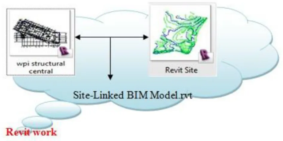
import or link the two Revit file together will get you the final site-linked 3D model
(Greenwold, 2007). The process is simple as the following picture shows, create two
separate files in Revit Architecture, one is for building model, the other is the site
model, then one choose to either link or import the two Revit files together.
Figure 2: Method 1 — Revit Architecture
menu in Revit Architecture, the model of site work becomes very limited,
theoretically, the pipe work can be done by created all the new elements as families,
however, it would be very time consuming and error-prone. Thus, if the proposed
project has a very complicated existing site condition, Revit Architect probably would
not be the best choice for the architect and engineers.
3.2.2
Method 2 — Revit Architecture & AutoCAD Civil
3D
Another feasible approach is to use AutoCAD Civil 3D to create the site model and
then link it with the building model either in Revit Architecture or AutoCAD Civil 3D.
Unlike Revit Architecture, the major aim of AutoCAD Civil 3D is to provide the BIM
solution for civil engineering rather than architectural design. As quoted from
Autodesk, ―the software focus on delivering higher-quality transportation, land
development, and environmental projects faster, explore design ideas and analyze
what-if scenarios to help optimize performance before projects are built (Autodesk
2011)‖. The intention for the use of this software determines the built-in features to
provide better site tools to model the site conditions, Civil 3D is functional in
modeling grading and intelligent pipe network, pipes and structures can be changed
simultaneously by using graphical or numerical input, and interference checking tool
would find any collision between the pipe system or pipe and the excavation for the
user. In other words, comparing to Revit Architecture, AutoCAD Civil 3D is more
functional for underground utility design. And since Revit supports the integration
with AutoCAD Civil 3D, the site data can be transferred between these two software‘s
efficiently, which means the 3D Revit Building model can be linked with modeled
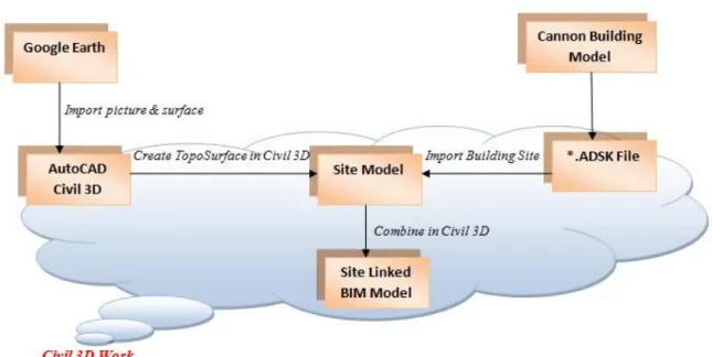
Figure 3 Method 2 — Revit Architecture & AutoCAD Civil 3D
However, standing from the visualization point of view, Civil 3D may not be as good
as Revit. To achieve a better visualization of civil engineering projects created in
AutoCAD Civil 3D, Navisworks could be considered (see Figure 3 above). Export
both the Civil 3D file and the Revit file as *.dwf format, and then merge the two flies
as one single model in Navisworks, this would provide a better visualization as well
as reduce resources of the models and improve coordination among different users.
3.2.3
Method 3— Bentley Products
The third method is to use Bentley products. This method is quite similar to method 2
(see Figure 4 below). InRoads/Power Civil is playing the role of Civil 3D while Bentley Architecture is taking Revit Architecture‘s place. One marked feature of
Bentley, comparing to Autodesk‘s products, is that it dedicates in delivering solutions
for the infrastructures rather than buildings. Specifically, Bentley products provide
efficient solutions for bridges, factories, roads, rail and transit. It also provides
buildings, roads, paving and assets. With its core design tools: Inroads site, power
civil and Geopak site, Bentley offers a complete solution for easy site modeling,
survey data management, digital terrain modeling, water/sewer line layout and
analysis, street design and so on. Similar to using Revit and Civil 3D, the process is to
use Bentley Architecture to create the building model, and then according to the
project information, chose either InRoads or PowerCivil to create the Site model, than
link them together. Bentley Navigators could be applied or not to integrate the two
models together.
Figure 4: Method 3 — Bentley products
3.2.4
Method 4 — ArchiCAD & Other BIM software
The fourth method is to use ArchiCAD to create the site model. ArchiCAD, as
architectural BIM software developed by the Hungarian company Graphisoft, could
be integrated with other BIM applications including Autodesk Revit and Civil 3D.
Although the mesh tool in ArchiCAD is not intended for Civil Engineering, still, it
could be used to present the virtual building by modeling terrain of the site model. To
create a topographic surface, one can either start out with a Scanned Image or in the form of a civil engineer‘s DWG files, import and simplifying the contour maps,
specific steps). One can also add roads to the site, develop terrain and paving meshes,
modeling foundations, cut a hole on site as excavations and so on (Graphisoft, 2011).
And since ArchiCAD has good file format compatibility, the site model could be
brought into other BIM software so that the building model and the site model could
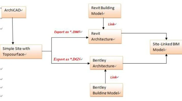
be linked together (see Figure 5 below). Some of the choices are, export the site model as AutoCAD‘s Vectorial DWF format, which is the supported format of Revit;
or export it as MicroStation‘s DGN, which would incorporate with Bentley products
(Graphisoft, 2011).
Figure 5: Method 4 — ArchiCAD & Other BIM Software
In conclusion, theoretically, all of these four methods could be applied in achieving a
site-building integrated model. However, since they are slightly different in design
functionalities, supported format and interoperability, the method should be chosen
under specific project circumstances. Method 1 and Method 4 are proposed to use single software for modeling both building and its‘ corresponding site, these two
methods, from the aspect of software investment, would be more economic; the
procedures are simpler since the two models could be created as the same format,
which would reduce some orientation and interoperable issues. However, the common
drawback of Revit Architecture and ArchiCAD is, both of these two software are
developed mainly for building design, they do not have the functionalities for site
design more than a simple topographic model. Therefore, if the project has a
complicated site condition, these two methods would not be considered as the best
choice.
Comparatively, method 2 and method 3 are using two different applications to model
the site and building separately, these would enable that more details could be
contained in the site model, the site model could provide the owner, the designer and
the civil engineers more detailed information, not only the topographic surface, but
also the soil type, landscaping, access roads, ground conditions and the location of site
utilities. Yet, by using more than one software product, the interoperability issues
need to be taken into account. The model needs to be imported and exported as
required format, the orientation needs to be coordinated before the integration, and to
achieve a better integration and visualization, Navisworks and Bentley Navigator
4.
Case Study
One case study was developed to explore and understand the details that involved in
creating a new site model and link it with the existing 3D building model. The project
selected for this case study is the WPI new sports & recreation center. It is currently
being constructed on the west side of WPI campus between Alumni Field, Morgan
Hall and Harrington Gymnasium.
The case study focus on two major parts of work, one is to explore how to create a
site model by using appropriate software and procedure, the other is to figure out how
to link the site and an existing building model together. This project has a very
complicated ground and underground conditions, there are a lot of underground
utilities need to be modeled. Thus, for the first part of work, according to the
discussion of technology support in Section 3, method 2 — Revit Architecture and
AutoCAD Civil 3D, conjunction with Google earth were used as the major computer
software to develop the model of the site. As for the second part of work, an existing
BIM structure building model created by Cannon Design Inc. was brought in
Autodesk Civil 3D to complete the sit-linked model.
The objectives of this case study are to address the following major issues:
• Provide a detailed feasible method to create site-linked BIM model by using Revit
Architecture and Autodesk Civil 3D.
• Compare the advantages and disadvantages of using different software to develop
the toposurface and to define the underground site conditions.
• Understand how many details can be involved in the site model and how this BIM
information can be used during the design and construction process, and further
• Explore the potential problems when link the building model and site model
together.
• Provide corresponding solution to the problems we met during the whole
developing process.
This case study would test the feasibility and provide a more specific procedures of
using Revit Architecture and AutoCAD Civil 3D to create a site-building integrated
model. The detailed process will be discussed and analyzed in the following section.
4.1
Previous Related Study at WPI
At first, this case study was developed to provide an alternative design to the
earth-retaining structure for excavation of the Worcester Polytechnic Institute new Sports
and Recreation Center to resist lateral loading during construction by a WPI Major
Qualifying Project (MQP) group. During the process of looking for a solution, the use
of Building Information Modeling was mentioned and considered to present a visual aid of the building‘s location on the WPI campus and to show the different phases of
excavation for the building by creating a construction site model (Moynihan, et al.,
2010). As Figure 6 and Figure 7 shows below, they created a toposurface with a
building pad on it, this simple model, although does not contain many details, shows
contour lines and elevations which were used to add 3 dimension to the site, and the
building pad is where the excavation took place. However, since they are using BIM
mainly for a visualization purpose, the work has not really been done rather than a
Figure 6 : MQP Work – Terrain Model from Front 1
Figure 7 : MQP Work – Terrain Model from Front 2
As a result of this work the following was found with regards to the site-building
• The Google earth picture of the site had to be exploded in civil 3D before
brought into Revit so a 3D topsurface can be reconstituted within Revit. If
you explode the picture in REVIT, the top surface becomes flat automatically. • Another issue is related to the elevation. When we tried to link the building
with the site; the elevation of the building will be imported as well, and since
the basic elevation (0‘00‘‘) of the site has been created automatically by the
software, you may have two different elevations at the same time, and this
would become an issue when you try to cut a pad within the site model in
Revit.
• Also, adjusting the location and direction (orientation) of the building is still
quite problematic because when you import the building within the site file,
you can either rotate the building and site as a whole together, or you can
rotate the building solely, but the site model, as the original file, cannot be
rotated solely.
Thus, addressing these issues became part of this research, which aims to figure out a
feasible way to create a site model that shows all the underground site condition
around the proposed building. The next section includes the general project
information, the process of defining the existing problems, proposing solution,
choosing appropriate software, specific working method, and the final result.
4.2
General Project Information
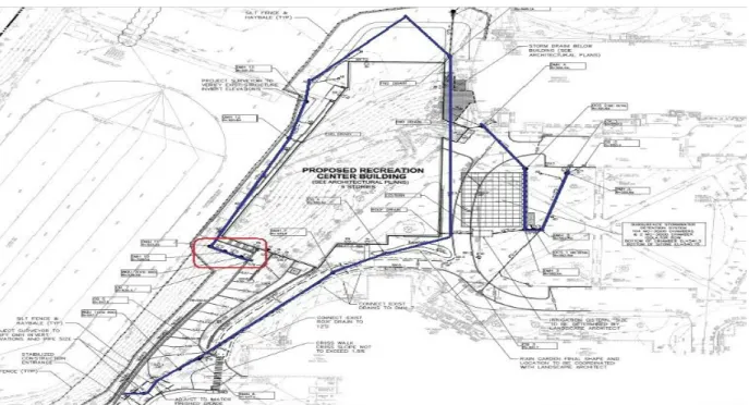
The rationale for the WPI new recreation and sports center can be summarized as follows: ―On October 30, 2009 the “WPI Board of Trustees voted unanimously
towards the construction of the 140,000 square-foot Sports and Recreation Center”
(WPI, 2009). The proposed building is currently being constructed and it is located
Harrington Gymnasium. The new facility, after completed, would contain a
natatorium, a fitness center, a four-court 29,000 square-foot gymnasium and an
indoor three-lane jogging track, as well as the handball courts, dance studios and
meeting spaces for the stuff of the Department of Physical Education, Recreation and
Athletics (WPI, 2009). Other specialized spaces include an indoor rowing tank,
racquetball and squash courts, well-equipped locker rooms and a training and
rehabilitation suite at field level. Aside from all of the athletic commodities, the new
building will also contain a robot pit to accommodate for the Robotic competitions, in
direct correlation with the new and growing Robotics major WPI offers. A corridor
will connect the existing Harrington Auditorium to the new building, creating larger
event space for career fairs, admissions open house, alumni events and conference
(Moynihan, 2010).” The issues related to this research were further explored in the
context of this facility.
During the design and construction phases, there is a lot of information coming from
different parties of this project. WPI is the owner of this project, cardinal construction is the owner‘s representative, and they have the basic requirement and expectation of
this project. The proposed building is designed by Cannon Design Inc., and it is
planned to be completed by Gilbane Inc., a leading building firm that is providing full
construction management as well as facilities-related services. Vanasse Hangen
Brustlin is the civil engineer and Haley Aldrich is the geotechnical engineer. So as
Figure 8 below shows, there are many models, reports, as built information from all of
these participants. That is why BIM was considered by the MQP group at the first
place, to help facilitate communication between different parties. Further application
Figure 8: Case Study – BIM as Integrated Information Resource
4.3
Existing problems
There are two major issues during the construction of this project.
Underground water table is high
Location of existing underground utilities
High Underground Water Table: One issue that the construction team cares a lot is
that the underground water table is very high at the construction site, thus, the
drainage system need to be set up before the excavation could take place. In addition,
the underground condition is complicated since there are a lot of pipes, manholes,
telephone lines, gas lines and so on around the building, and if the information of
these underground situations is unknown, it would make the further construction
become risky and difficult.
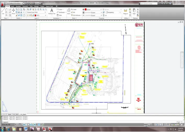
information on hand such as the soil borings, civil drawings that shows the general
proposed site information including grading, drainage, erosion control plan, utility
plan and site details, they also have the Auto CAD design and construction drawings
that show the as built site information produced by the excavation contractor (Figure
9). However, none of these documents are 3D format, they are either notes, paper
drawings or 2D CAD drawings, these documents carry the necessary site information
for civil engineer and construction team, however, it is hard to tell from these
descriptions and drawings where the exact corresponding ‗Z‘ coordinate location of
each item is. The real construction site is not like a flat drawing, it is 3-dimensional,
every single pipe, catch basin, manholes has its location, not only defined by the simple (x, y), but also the ―z‖ which decides its elevation. And without knowing the
elevation, none of these items can be really defined on site. Hence, this case study,
based originally on the work that has been done by the MQP group, has continued
researching on how to convert this 2D information into a 3D site model, and finally
deliver a site-linked 3D building model that carries all the necessary information that
Figure 9 : CAD Drawing – As Built Utility Information (Provided by Gilbane Inc., 2011)
4.4
Specific Concerned Issues & Proposed Solutions
To start creating a site linked BIM model for this project, three major steps need to be
followed in order. First step is to choose the appropriate software according to the
current accessibility, then compare and decide the procedures of creating a site model
and link it with the existing building model, the last step is figure out what the
specific issues of this project are and provide the corresponding solutions. An
expanded discussion could be found in the following sections.
4.4.1
Selection of the Appropriate Software
into a 3D topographic surface, which would show the terrain of the existing site where
the construction would be developed. This simple model, even without any
underground information like pipes and ducts, can still be used by architect, engineer
and also the construction team to get a general idea of how the planned site look like,
where the excavation would probably take place, which place can be considered to
store materials, equipment, and etc. Also, this sketchy model is the foundation of the
following steps and will be carried through the construction phase for further
development.
Based on what has been discussed in the prior chapters, there are several ways to
create a toposurfarce, either Revit, AutoCAD Civil 3D, InRoads and ArchiCAD can
be used to accomplish this task. The MQP group chose to use the process of ―Google
Earth-Civil 3D-Revit Architecture‖ to realize this task, yet, in this case, AutoCAD
Civil 3D over Revit Architecture has been chosen to accomplish most of the site part
for the following reasons:
• Less Software Involved & Simpler Procedure
Generally speaking, there are two ways to create a 3D toposurface. One is to use Civil
3D to explode the Google earth picture and then bring it into the Architectural Revit,
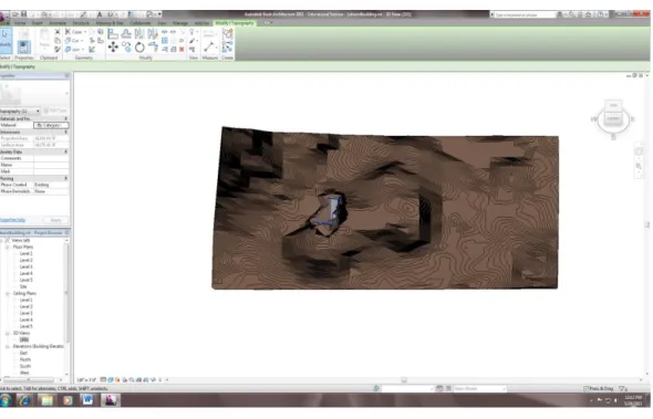
then in Revit screen, click the tab of Create toposurface, select the corresponding lines
that you need to display(C-TOPO-MAJR, C-TOPO-MINR in this case), and then you
Figure 10 : Procedure 1 – Create Toposurface in Revit
The other method (Figure 11) is to import the site picture and surface directly from
Google Earth to Civil 3D, define the insert point (x,y,z) to put the site, it would appear
as a 3D site automatically in Civil 3D. This second method was selected, considering
to bring the Revit building model later into Civil 3D, by using this method, most of
the site modeling work can be done in Civil 3D, rather than Revit, which is much
Figure 11 : Procedure 2 – Create Site Model in AutoCAD Civil 3D
• More Powerful functionalities
Both Revit and AutoCAD Civil 3D has been developed to have powerful
functionalities for site design and landscape. However, each of them has different
strength and limitation in different design areas, the following table was prepared
depending on my own using experience and the information provided by Master
Graphics, Inc. in 2008.
Functionalities Comparison: Revit Architectural Vs. Auto CAD Civil 3D
Tool Available Tool Not Available
Functionalities Revit Architecture Revit MEP Auto CAD Civil 3D
View 3D Modeling Piping Pipe Structure Pipe Accessories Plumbing Fixture Site Toposurface Subregion Split Surface Merge Surfaces Grading Property Line Site Components Label Contours Tools
Earth Volume Calculation
Heating & Cooling Loads
Check Duct Systems
Check Pipe Systems
Table 2: Functionalities Comparison: Revit Architectural Vs. Revit MEP Vs. AutoCAD Civil 3D — based on graphic from Master Graphics, Inc. 9/23/2008
According to the information provided in the table above, apparently, Autodesk Revit
Architecture provide a better appearance of the 3D model, building pad can be easily
added into an exist toposurface, the 3D view including the landscape is more vivid
and realistic. However, it has an obvious limitation in defining the underground site
condition. Pipe system, which is the key point in this case study, cannot be defined in
electrical and plumbing (MEP) design, yet, this software is usually used to define the
within building MEP system, not the underground existing one. So it lacks the
functionalities in defining the exit site condition such as the surface, contours, grading
and other possible site components. Thus, overall speaking, although AutoCAD Civil
3D is not perfect in the part of 3D view, it has some standout features in defining the
site components as well as an existing underground MEP system, plus, it provides
various tools to calculate the excavation volume, and check the pipe system.
4.4.2
Define Existing Underground Site Condition—
Utilities
According to the set of drawings and the 2D as built CAD drawing, the underground
utilities condition that may affect the construction can be divided into the following
categories:
• Pipe Drainage System
• Sewage System
• Electrical Line
• Telephone Line
• Gas Line
Dewatering: Before the construction took place, a total of eight test borings, designated B101 through B109 were conducted at the project site by Seaboard
permit observation of stabilized water levels. According to the Geotechnical
report prepared by Haley & Aldrich, Inc. Boston, Massachusetts, the
groundwater was observed at a depth below grade of 8.5 to 21 feet (EL. 512.5
to EL. 534), and in advance of excavation, to prevent disturbance of
foundation bearing soils and potential excavation instabilities, the water level
should be lowered and maintained in the soil to minimum of 2 feet below the
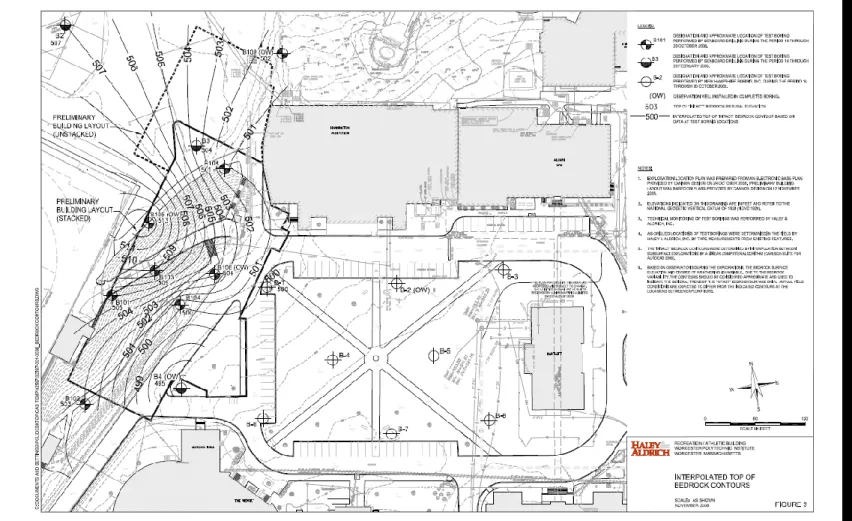
As the 2D pdf drawing C-3.0 (Figure 13 below) and the CAD drawing (Figure
9) shows, the blue line indicates the drainage line. Mainly, there are two long
drainage pipes around the building, as well as 13 drainage manholes, several
catch basin, water quality unit and a storm water detention system on site that
connect different part of the pipes. In the CAD drawing, we can find out one
pipe starts from the southwest corner of the building, goes all the way up along
the west side of the foundation and ends at the north side of the building as
manholes, the pipe that coming from the drainage manhole 15 goes into the
building. The other pipe starts from the very south, connects with a storm
water detection system on the east side, and then goes up along the building
and connects with the first pipe at the north side.
Figure 13: Structural Precast Concrete Bid Package C-3.0 (Cannon Design)
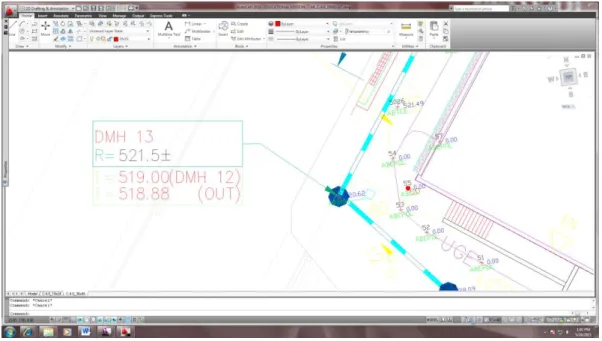
As Figure 14 shows, the elevation of each drainage manhole is marked in a