Satbir Malik, Surinder SinghIJSRE Volume 05 Issue 04 April 2017 Page 6291
Volume||5||Issue||04||April-2017||Pages-6291-6298||ISSN(e):2321-7545 Website: http://ijsae.in Index Copernicus Value- 56.65 DOI: http://dx.doi.org/10.18535/ijsre/v5i04.01
LQR and Tuned PID Controller Design and Simulation for Aircraft Pitch Control
Using
MALTABAuthors
Satbir Malik1, Surinder Singh2
Department of Instrumentation (U.S.I.C.) Kurukshetra University, Kurukshetra Kurukshetra, India E-mail: satbirmalik42@, [email protected]
ABSTRACT:-
This paper presents a MATLAB based comparative analysis between classical and modern controller for a control system which are based on a pitch of an aircraft system and time response specification performance. The controller designed on the basis of dynamic modeling of the system that demonstrate the derivation of mathematical model for presenting the longitudinal motion of the aircraft. Pitch angle for an aircraft system is developed by using PID controller, LQR controller. By using MATLAB, we will tune the parameters of the PID controller and also minimize the IAE(Integral Absolute Error), ISE(Integral Square Error), ITAE(Integral Time Absolute Error) in estimation tool manager. Simulation result presents the response of Pitch Controller and in step response. Finally the step response of the pitch angle control system is demonstrated and analysis based on a common criterion of response of the system in order to identify which control strategy provides the better performance with the desire trajectory of the pitch angle control system. From the simulation it is clear that LQR controller performance is better as compared to PID controller.
Keywords :- ISE, LQR, ITAE, PID, MATLAB, IAE, Pitch
INTRODUCTION -
Flight accidents and misshapes have motivated researchers for decades to improve the flight control system. The conventional method to ensure reliable performance in case of an actuator failure has beento introduce more and more functionally redundant hardware elements. The main motivation for controller design is that the increase in survivability and safety of the passengers. A controller should allow acceptable performance for control of the aircraft under a number of shortcomings orfault conditions.
Today‟s aircraft and missile consist of number of automatic controller that helps the airplane crew in airplane management and piloting the aircraft.The development and advancement of the autopilots increases after the successful development man-carrying aircraft by wright brothers [2].Usually, aircraft and missile contains three rotational motions and three translational motions [2]. Furthermore, the control strategies of aircraft can be grouped into two categories, as follows lateral and longitudinal control [2]. In longitudinal control the pitch angle whereas in lateral control roll and yaw of an aircraft system is controlled.
Satbir Malik, Surinder SinghIJSRE Volume 05 Issue 04 April 2017 Page 6292
control pitch of an aircraft and ailerons are used to control roll of an aircraft. The ultimate aim is to follow the elevator and ailerons command with minimum delay and maximum accuracy.
MATHEMATICAL MODELING FOR AIRCRAFT PITCH CONTROL SYSTEM -
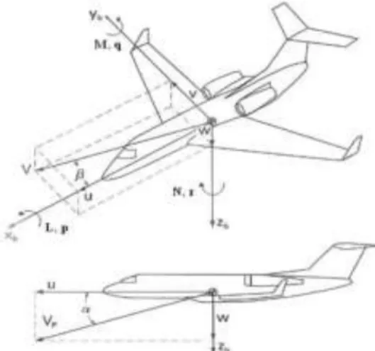
Pitch control is a longitudinal control; therefore longitudinal model of an aircraft is used to design the pitch angle controller of an aircraft. The aircraft pitch control system is shown in Fig. 1 where , and indicate the aerodynamics force components and θ, Ф and δe indicate the pitch angle, roll angle and elevator deflection angle respectively in the earth-axis system.The aerodynamic moment components are represented as L, M and N, angular rates as p, q and r and velocity components as u, v, and w for roll, pitch and yaw respectively in the body fixed coordinate of aircraft system as shown in Fig. 2. α indicates the angle of attack and β indicates sideslip angle as shown in Fig. 2.2.
Fig. 1 Pitch control system of an aircraft
In this section mathematical model of pitch control system of an aircraft is derived. Certain assumptions are to be considered to reduce the complexity of analysis, aircraft is assumed as a rigid body and its motion consist of small disturbances due to external conditions [2]. The equation of motion of an aircraft can be separated as the lateral and longitudinal equations.
Fig. 2 Moment, force and velocity components in body fixed coordinate Certain assumptions are required for mathematical modeling of an aircraft.
First, the variation in pitch angle does not alter the speed of an aircraft.
Second, the aircraft is moving at constant velocity and altitude, thus the lift and weight balance out and the thrust and drag cancel out each other.
Satbir Malik, Surinder SinghIJSRE Volume 05 Issue 04 April 2017 Page 6293
( ̇ ) (2.1)
( ̇ ) (2.2)
̇ ( ) ( ) (2.3)
Certain assumptions need to consider solving the aircraft problem: 1) Pitch angle ̇
2) Pitching rate ̇ ̇
3) Roll angle ̇ 4) Rolling rate ̇ ̇
5) Yaw angle ̇ ( ) 6) Yawing rate ̇ ̇
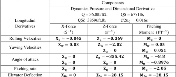
Table I Longitudinal Stability Derivative Parameters
Longitudinl Derivatives
Components
Dynamics Pressure and Dimensional Derivative Q = 36.8lb/ft2, QS = 6771lb,
̅=38596ft.lb, ̅/2 = 0.016s
X-Force
( )
Z-Force
( )
Pitching
Moment ( )
Rolling Velocities
Yawing Velocities
̇
̇
Angle of attack
̇
̇
̇
Pitching rate
Elevator Deflection
pitch control system [2] used are given in Table 2.1.Here the data for system modeling and analysis is taken from General Aviation Airplane [1], [2].
Small disturbance theory can be used to linearize (2.1), (2.2) and (2.3). The variables are substituted as given in (2.4) by introducing the small perturbation or disturbance.
m
(2.4)
For simplicity certain assumptions are taken. First, the reference aircraft conditions are considered to be symmetric and second, the propulsive forces are considered to be same throughout the flight i.e.
. After linearization the (2.5), (2.6), and (2.7) are obtained.
(
) ( ) ( ) [( )
] [( ) ] ( )
(
) ( ) ( )
Satbir Malik, Surinder SinghIJSRE Volume 05 Issue 04 April 2017 Page 6294
( ) ( )
( ̇ ) ( )
( ̇ ) ( )
( )
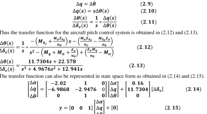
The transfer function of variation in pitch angle to the variation in elevator angle can be obtained from the (2.8) as under.
̇ ( ) ( ) ( ) ( )
( ) ( )
( )
( ) ( )
Thus the transfer function for the aircraft pitch control system is obtained in (2.12) and (2.13).
( ) ( )
( ̇ ) ( )
( ̇ ) ( )
( )
( ) ( )
( )
The transfer function can also be represented in state space form as obtained in (2.14) and (2.15).
[ ̇ ̇ ̇
] [ ] [
] [ ] [ ] ( )
[ ] [
] [ ] ( )
Mathematical modeling of Aircraft pitch control system is presented in this chapter. This helps to understand the aircraft system mathematically so as to find the key issues to work upon and simulation.
PID CONTROLLER
PID control is the basic control scheme of the classical control system. It is mainly used for industrial control of a number of processes due to its simplicity [6]. The performance of the system can be enhanced [7] by tuning the proper value of gain , and . The mathematical equation for PID controller of an plant with input u(t) output y(t) and the error, e(t) is expressed as (3.1), (3.2) and (3.3) where is proportional gain, integral gain, derivative gain, integral time and derivative time. PID control is combination of proportion (P), integral (I), differential (D) of the error ( ). The block diagram of analog PID control system is shown in Fig. 3.1.
Fig. 3 PID controller with aircraft pitch control system
( ) ( ) ∫ ( ) ( )
( )
( ) ( ( ) ∫ ( ) ( )
) ( ) ( ) ( ) ( ) ( )
Proportional gain helps in increasing the loop gain of the system to make it immune to load disturbance.
Satbir Malik, Surinder SinghIJSRE Volume 05 Issue 04 April 2017 Page 6295
stability of closed loop system. The parameters of PID controller have to be chosen properly to achieve the desired performance. The parameters of PID controller have to be chosen properly to achieve the desired performance. There are number of methods available in literature for tuning of PID controller such as Ziegler Nichols, Tyreus and Luyben methods and also done by using MATLAB.
LQR Controller-
Linear-quadratic-regulator (LQR) is technique in control system that is widely used in many control applications [6]. It is an optimal control strategy. In the design of LQR the value of the gain K is chosen such that the performance index J is optimized. This assures that the feedback gain K is optimal for the performance index specified. The performance index J is defined as given by (3.11)
∫ ( ) (3.11)
Where „Q‟ and „R‟ are gain matrices which must be positive semi definite. It is a methodology in modern control system that optimizes the value of performance index J. It uses the feedback control strategy to analyze a system. The system can be stabilized by choosing the proper value of feedback gain K. The feedback control law that minimizes the value of the cost is given by
(3.12) Where K is given by
(3.13)
And the value of P is computed by solving the continuous time algebraic riccati equation (ARE).
(3.14)
The block diagram of this system is shown in Fig. 3.2
Fig. 4 Full-state feedback controller with reference input.
Pre compensation is used to reduce the steady state error ( ) of the output ( ). Pre compensated gain
̅can be used after the input ( ). Value of gain ̅can be computed using the MATLAB user defined
function.
Design of LQR controller, it is required to calculate the value of the gain K. it is calculated using algebraic riccati equation (ARE) by choosing appropriate values of Q and R. The controller can be tuned by varying the value of Q and R matrix by varying matrix to get the desired performance characteristics.
RESULTS AND DISCUSSION –
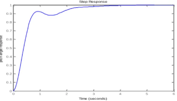
The LQR and PID controllers are designed to control the pitch angle of an aircraft. Simulation is done within the MATLAB for analysis of the both control schemes. MATLAB simulation results for the pitch angle response of an aircraft are given in step‟s response and the performance is measured in terms of rise time ( ), settling time( ), peak overshoot ( ) and steady state error ( ) for pitch angle response of an aircraft.
Satbir Malik, Surinder SinghIJSRE Volume 05 Issue 04 April 2017 Page 6296 Table II Desired performance specifications
Response Characteristics Pitch angle response
Rising time( ) 1 s
Settling time( ) 0.2 s
Percentage overshoot (% ) 5%
Steady state error ( %) 2 %
Finally, we found that LQR Controller gives better result as compare to PID controller.
Fig. 5 Pitch angle response of an aircraft closed loop system without using any controller
Table III Pitch angle response for closed loop system without using any controller
Response Characteristics Pitch angle response for closed loop
system without using any controller
Rising time( ) 2.1 s
Settling time( ) 4.2 s
Percentage overshoot (% ) 0 %
Steady state error ( %) 0.1 %
Fig. 6 Pitch angle response with PID controller based on ISE
Fig. 7 Pitch angle response with LQR Controller
0 1 2 3 4 5 6
0 0.1 0.2 0.3 0.4 0.5 0.6 0.7 0.8 0.9 1
Step Response
Time (seconds)
pi
tc
h
an
gl
e
re
sp
on
se
0 20 40 60 80 100 120 140 160 180 0
0.05 0.1 0.15 0.2 0.25
Step Response
Time (seconds)
pi
tc
h
an
gl
e
re
sp
on
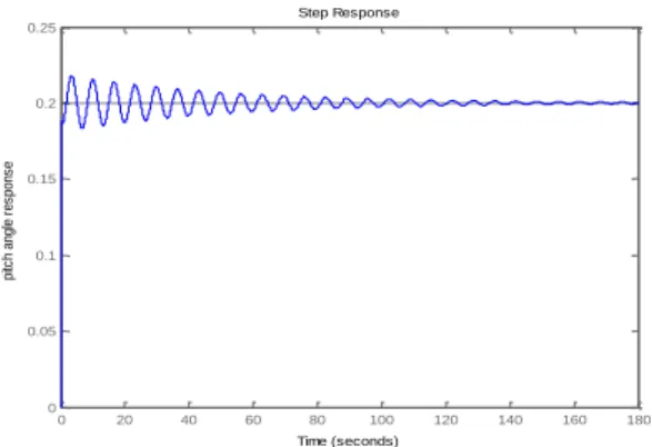
Satbir Malik, Surinder SinghIJSRE Volume 05 Issue 04 April 2017 Page 6297 Fig. 8 Pitch angle response with PID controller based on IAE
Fig. 9 Pitch angle response with PID controller based on ITAE
Table- IV. Summarry of performance characteristis of pitch angle
Response characteristics Pitch angle
LQR (x=100)
PID
ISE IAE ITAE
Rising time(Tr) 0.198s 0.743s 0.751s 0.751s
Settling time(Ts) 0.535s 33.5s 76.2s 76.2s
Percentage overshoot(%OS) 4.18 8.17 8.89 8.89
Steady state error(%ess) 0.2 0.2 0.2 0.2
CONCLUSION
In this work, design of aircraft pitch control system is designed and analyzed successfully. Pitch controller of an aircraft is required to stabilize the pitch angle at it desired value. PID, LQR strategies are designed successfully. Referring to results, it is observed that the control tuned by LQR controller gives better performance when compared to PID Controller. For further research, to design roll and yaw controller design to make complete autopilot for an aircraft. Effort can be made to make more advanced and adaptive control techniques can be developed and applied to control an aircraft. Performance of these controllers is widely dependent upon the choice of its parameters, hence tuning of these parameters to find their optimal values is at most important.
REFERENCES
1. Nurbaiti Wahid, Nurhaffizah Hassan, “Self-tuning Fuzzy PID Controller Design for Aircraft Pitch Control”, Intelligent Systems, Modeling and Simulation (ISMS), Third International Conference on
Intelligent Systems Modeling and Simulation, 2012 IEEE, pp 19-24.
2. Robert C. Nelson, Flight Stability and Automatic Control, McGraw Hill, Second Edition, 1998. 0 20 40 60 80 100 120 140 160 180
0 0.05 0.1 0.15 0.2 0.25 Step Response Time (seconds) p itc h a n g le r e s p o n s e
Satbir Malik, Surinder SinghIJSRE Volume 05 Issue 04 April 2017 Page 6298
3. N. Wahid, M.F. Rahmat, “Pitch Control System Using LQR and Fuzzy Logic Controller”, Industrial
Electronics & Applications (ISIEA), IEEE Symposium on Industrial Electronics Malaysia, 2010,
pp.389-394.
4. N. Wahid, M.F. Rahmat, K. Jusoff, “Comparative Assessment Using LQR and Fuzzy Logic Controller for a Pitch Control System”. European Journal of Scientific Research, vol. 42, no 2, pp.184-194, 2014.
5. Amir Torabi, Amin AdineAhari, Ali Karsaz, S.H. Kazemi “Intelligent Pitch Controller Identification and Design”, Journal of mathematics and computer science, pp.113-127, 2014.
6. M.Gopal, “Control Systems Principles and Design”, Second Edition, Tata McGraw Hill, 2002. 7. Mohd S. Saad, HishamuddinJamaluddin, Intan Z. M. Darus, “PID Controller Tuning Using
Evolutionary Algorithms”, WSEAS Transactions on System and Control, vol. 7, pp. 2224-2856, 2012.